EP2468985A1 - Dispositif de revêtement de sol pour systèmes de scènes, de tribunes ou de podiums - Google Patents
Dispositif de revêtement de sol pour systèmes de scènes, de tribunes ou de podiums Download PDFInfo
- Publication number
- EP2468985A1 EP2468985A1 EP11009418A EP11009418A EP2468985A1 EP 2468985 A1 EP2468985 A1 EP 2468985A1 EP 11009418 A EP11009418 A EP 11009418A EP 11009418 A EP11009418 A EP 11009418A EP 2468985 A1 EP2468985 A1 EP 2468985A1
- Authority
- EP
- European Patent Office
- Prior art keywords
- corner
- floor covering
- covering device
- connector unit
- corner connector
- Prior art date
- Legal status (The legal status is an assumption and is not a legal conclusion. Google has not performed a legal analysis and makes no representation as to the accuracy of the status listed.)
- Granted
Links
Images


Classifications
-
- E—FIXED CONSTRUCTIONS
- E04—BUILDING
- E04H—BUILDINGS OR LIKE STRUCTURES FOR PARTICULAR PURPOSES; SWIMMING OR SPLASH BATHS OR POOLS; MASTS; FENCING; TENTS OR CANOPIES, IN GENERAL
- E04H3/00—Buildings or groups of buildings for public or similar purposes; Institutions, e.g. infirmaries or prisons
- E04H3/10—Buildings or groups of buildings for public or similar purposes; Institutions, e.g. infirmaries or prisons for meetings, entertainments, or sports
- E04H3/22—Theatres; Concert halls; Studios for broadcasting, cinematography, television or similar purposes
- E04H3/24—Constructional features of stages
-
- E—FIXED CONSTRUCTIONS
- E04—BUILDING
- E04H—BUILDINGS OR LIKE STRUCTURES FOR PARTICULAR PURPOSES; SWIMMING OR SPLASH BATHS OR POOLS; MASTS; FENCING; TENTS OR CANOPIES, IN GENERAL
- E04H3/00—Buildings or groups of buildings for public or similar purposes; Institutions, e.g. infirmaries or prisons
- E04H3/10—Buildings or groups of buildings for public or similar purposes; Institutions, e.g. infirmaries or prisons for meetings, entertainments, or sports
- E04H3/12—Tribunes, grandstands or terraces for spectators
-
- E—FIXED CONSTRUCTIONS
- E04—BUILDING
- E04H—BUILDINGS OR LIKE STRUCTURES FOR PARTICULAR PURPOSES; SWIMMING OR SPLASH BATHS OR POOLS; MASTS; FENCING; TENTS OR CANOPIES, IN GENERAL
- E04H3/00—Buildings or groups of buildings for public or similar purposes; Institutions, e.g. infirmaries or prisons
- E04H3/10—Buildings or groups of buildings for public or similar purposes; Institutions, e.g. infirmaries or prisons for meetings, entertainments, or sports
- E04H3/22—Theatres; Concert halls; Studios for broadcasting, cinematography, television or similar purposes
- E04H3/24—Constructional features of stages
- E04H3/28—Shiftable or portable platforms
-
- E—FIXED CONSTRUCTIONS
- E04—BUILDING
- E04F—FINISHING WORK ON BUILDINGS, e.g. STAIRS, FLOORS
- E04F15/00—Flooring
- E04F15/02—Flooring or floor layers composed of a number of similar elements
- E04F15/024—Sectional false floors, e.g. computer floors
- E04F15/02447—Supporting structures
- E04F15/02458—Framework supporting the panels
Definitions
- the present invention relates to a floor covering device for stage, grandstand and podium systems or the like event systems with a floor covering, on the edge region of the floor covering existing Tragrandprofilen on which the floor is stored and each at least one open to the corner, in particular longitudinally continuous cavity have, in the corner abutting Tragrandprofile connected to this corner connector unit with two legs and a connected to the corner connector unit Steckbeinlessnessü for releasably connecting a plug leg.
- a decking device of the type mentioned is from the EP 1370 763 B1 known. This is used as part of a component system that has proven itself in practice and is used in a variety of ways. As part of the disposal of large covering surfaces such decking devices are laid side by side and mounted on the support edge profiles in main support profiles, which in turn are connected to stems that are present in the corner.
- the proven connection technology of the Layher Allround Scaffolding System (registered trademark), in which the slotted connection heads of the Main support profiles are pushed onto an existing on the stem perforated disk and then connected by driving a wedge. In this case, the stems can be present over respective floor covering devices, so that additional components can be connected in terms of height.
- a separate plug leg holder which has L-shaped legs which are screwed on the inside of the support profiles in the corner outside with the wall of the supporting edge profiles of the floor covering device.
- a slotted piece of pipe is welded on the inside, into which a leg insertion can be inserted and then fixed by clamping.
- the support edge profiles are always formed thinner walls, so that the known Steckbeinan gleichvorraumen come in terms of required stiffness and load capacity to its limits.
- the present invention the object or the technical problem of specifying a floor covering devices of the type mentioned, which can be produced economically, a simple installation, in particular with regard to the connection of a Steckbeinprofiles, guaranteed and beyond a high Stiffness and load capacity in the connection area of the leg profile allows.
- the floor covering device according to the invention is given by the features of independent claim 1.
- Advantageous embodiments and further developments are the subject of claims dependent directly or indirectly from the independent claim 1.
- the floor covering device is accordingly characterized in that the legs of the corner connector unit have a transverse recess, in the transverse recess an insert part is arranged, the insert part has mating connection means, the legs of the corner connector unit are respectively inserted in the cavity of the support edge profiles and from externally accessible connection means are present, which are connected via the wall of the Steckbeinamiser the respective support edge profile and the Eckverbinderü with the counter-connection means of the insert part, so that the Steckbeinaiser is connected in the corner with the adjacent support edge profiles.
- Such a floor covering device ensures a high rigidity and load capacity in the connection area of the leg profile.
- the deformations occurring under load can easily be kept within the permitted range.
- An economical production is ensured by the fact that the connection of the corner connector unit and the Steckbeinafterhim can be mounted in a simple manner.
- a particularly preferred embodiment which ensures high stiffness values, is characterized in that the insert part is circumferentially positively arranged in the transverse recess of the legs of the corner connector unit, wherein a particularly advantageous additional development is characterized in that the legs of the corner connector together with the respective insert part are arranged in a form-fitting cross-section respectively in the cavity of the supporting edge profiles.
- the externally accessible connection means are preferably designed as one, in particular two, spaced apart screw / n and the counter-connection means designed as a nut, which allows a very simple connection technology, which ensures a durable reliable function with high payloads.
- second connection means are preferably present which fix the insert unit within the corner connector unit and at the same time provide a connection of the corner connector unit to the support edge profiles, so that the covering floor device also without the additional connection of a Steckbeinageü can be used.
- the second connection means are preferably formed as a rivet.
- a particularly advantageous embodiment which enables economic production, a high load-bearing capacity and reliable positioning of the counter-connection means, is characterized in that the insert part is formed as a solid profile component, wherein plastic is preferably used as material, which fixes the counter-connection means in the desired position , wherein a plastic injection molding method is preferably used for producing the insert part.
- corner connector unit is formed as an extruded profile, in particular as an aluminum extruded profile.
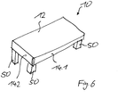
- Fig. 6 is in a perspective plan view of a decking device 10 is shown, which has a substantially rectangular floor covering 12, which is circumferentially surrounded by Tragrandprofilen 14.1, 14.2 in the edge region on which the floor covering 12 is connected, and in the corner region each side has a connected cut leg profile 50.
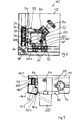
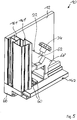
- the detail A that is the corner area, is in the FIGS. 1 to 5 shown in more detail.
- Fig. 1 the detail A is shown in an exploded view in a bottom view.
- the flooring device 10 has a first support edge profile 14.1 and a second support edge profile 14.2. Both support edge profiles 14.1, 14.2 have a different cross-sectional profile, which is optimized in terms of its load capacity due to the predetermined geometry of the flooring device 10. Both support edge profiles 14.1, 14.2 have directly below the bearing surface of the lining bottom 12 a first and a second, longitudinally continuous and open towards the corner cavity 16.1, 16.2, which is the same in cross-sectional geometry and is arranged in the corner at the same height level. In the corner, a corner connector 18 is present, which is designed as an extruded profile.
- the corner connector unit 18 has a first leg 20.1 and a second leg 20.2, which are formed as hollow profiles with a continuous first transverse recess 30.1 or 30.2.
- an insert 32 is present, which has a corresponding to the inner peripheral contour of the first and second transverse recess 30.1, 30.2 Vollprofilrechteckquerites and in the first transverse recess 30.1 and second transverse recess 30.2 can be positively inserted, wherein in the inserted state, the top and bottom of the insert part 32nd is flush with the first leg 20.1 and second leg 20.2.
- the first leg 20.1 is at a right angle to the second leg 20.2, corresponding to the connection angle of the first supporting edge profile 14.1 to the second supporting edge profile 14.2.
- the cross section of the first leg 20.1 or 20.2 is formed perpendicular to the longitudinal direction so that the first leg 20.1 and the second leg 20.2 can be inserted into the cavity 16.1 or 16.2 of the supporting edge profile 14.1 or 14.2.
- the insert 32 has mating connection means 26 which are formed as two longitudinally spaced nuts and fixed within the solid cross section of the insert 32.
- the insert 32 may be formed, for example, as a molded plastic component.
- a teilausEnglishung 38 is present on the insert part 32 approximately in the center.
- two spaced EckverbinderausEnglishept 42 are present, which are aligned with inserted insert 32 with the mating terminal means 26 (nut) of the insert. Furthermore, between the EckverbinderausEnglishept 42 a leg connection recess 44 is present, which is aligned in the inserted state of the insert member 32 with the insertion recess 38.
- the inner wall of the first supporting edge profile 14.1 and the second supporting edge profile 14.2 have two Tragrandprofilausnatural insects 46, which are aligned with the EckverbindrungsEnglishept 42 of the corner connector unit 18 in the cavities 16.1 and 16.2 introduced state of the first and second leg 20.1, 20.2.
- a Profilan gleichausnaturalung 48 is present, which in the retracted state of the first or second leg 20.1, 20.2 of the corner connector unit 18 are aligned with the Schenkelan gleichausnaturalung 44.
- the insert part 32 is first inserted flush into the first transverse recess 30.1 / second transverse recess 30.2 of the first leg 20.1 / second leg 20.2 of the corner connector unit 18. Thereafter, the first leg 20.1 or 20.2 is inserted into the first cavity or second cavity 16.1 or 16.2 of the first support edge profile 14.1 or 14.2.
- each of the insert recess 38 is aligned with the Schenkelan gleichausEnglishung 44 and the Profilan gleichausEnglishung 48.
- second connection means 28 are attached, which are each formed as a rivet.
- the corner connector unit 18 is fixed to the first support edge profile 14.1 or second support edge profile 14.2.
- about the Tragrandprofilausströmriossianung 46 and the Eckverbind somehowsEnglishept 42 each of the threads of the nuts of the counter-connection means 26 is accessible from the outside.
- the outer walls each have two spaced connection recesses 52 which are aligned with attached Steckbeiningiser 22 with the TragrandprofilausEnglishache 46 and the Schenkelan gleichausnaturalungen 44 so that formed as a screw first connection means 24 for establishing the connection with the Counter connection means 26 of the respective insert part 32 can be connected.
- the Steckbeiningiser 22 in a simple manner in case of need quickly and reliably mounted in the corner, in particular by the solid wall insert 32, it is possible to allow high stiffness and load even at low wall thicknesses of the first Tragrandprofile 14.1 and second Tragrandprofilen 14.2.
- the plug leg receiving unit 22 has a downwardly open receiving opening 64 into which the cut leg profile 50 can be inserted.
- a receiving opening 64 In the interior of the receiving opening 64 protrude in the region laterally of the lining floor corner in each case a fixing projection 60 into which the cut leg profile 50 comes to the outside of the display.
- a substantially U-shaped receiving projection 62 is formed within which a pressure piece surface unit 36, is arranged displaceable inwardly. From the outside, the pressure pad unit 36 is under the action of a Fixierschraubeniki 34, that is, by pressing the Fixierschraubenü 34 it is moved depending on the direction of rotation inward or outward and thus fixed the inserted Mitteilprofil 50 by clamping or dissolved.
- the receiving projections 62 or the pressure piece surface unit 36 are formed with respect to their investment geometry to the cut leg profile 50 out so that both a square and a round cut leg cross-sectional profile can be inserted and clamped.
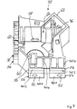
- the two outer walls which are facing the first support section 14.1 and the second support section 14.2 when the Steckbeinfactaku 22 attached, have the same geometric structure (see, for example Fig. 7 ).
- Fig. 7 has one of these outer walls to the viewer and others facing to the left, the Steckbeinfactiser 22 in Fig. 7 is shown in a subview.
- first projection units 54 each having a Stirnend Chemistry 40.1, in which the connection recess 52 is present.
- second projection unit 56 with the front end face 40.3 is arranged in each case.
- a recessed front end face 40.2 Between the first projection unit 54 and the end face 40.3 of the second projection unit 56 there is a recessed front end face 40.2. Above the second projection unit 56 is a recessed Stirnend constitutional 40.4.
- connection recess 52 which is provided on the left first projection unit 54.
- this connection recess 52 is accessible from the outside by a screwing tool.
- right connection recess 52 is as out Fig. 1 can be seen from the outside directly from its back by a screwing accessible.
- second projection unit 56 in conjunction with the Stirnend vom 40.1, 40.2, 40.3, 40.4 is sufficient contact surface for engagement with the inwardly facing outer wall of both the first support edge profile 14.1 and the second support edge profile 14.2 available, so that even with a relatively thin wall thickness of the support edge profiles 14.1,14.2 in conjunction with the inserted into the corner connector unit 18
- Insert 32 is available as a solid profile connection that ensures high rigidity while maintaining high load capacity. At the same time, there is a connection technology, which is very simple in terms of assembly, of a clip-leg receiving unit 22 to a pad-type bottom device 10, which can be quickly assembled or disassembled as needed.
- Fig. 1 is additionally shown below the Steckbeinageiser 12 on the Steckbeinanceiser 12 releasably attachable Eckformiser 66, which complements the bevelled corner of the lining floor 12 and the entire corner to a 90 ° - corner.
- the corner molding unit 66 is preferably made of plastic.
- a cover unit 68 is shown, by means of which the introduced into the Steckbeinfactajiaku 22 pressure piece surface unit 36 is secured in the absence of Fixierschraubenatti 34 in its installed position and at the same time forms a protection against contamination.
Landscapes
- Engineering & Computer Science (AREA)
- Architecture (AREA)
- Civil Engineering (AREA)
- Structural Engineering (AREA)
- Multimedia (AREA)
- Floor Finish (AREA)
Priority Applications (1)
| Application Number | Priority Date | Filing Date | Title |
|---|---|---|---|
| PL11009418T PL2468985T3 (pl) | 2010-12-23 | 2011-11-29 | Urządzenie podestowe dla systemów scen, trybun i podiów |
Applications Claiming Priority (1)
| Application Number | Priority Date | Filing Date | Title |
|---|---|---|---|
| DE102010055811A DE102010055811A1 (de) | 2010-12-23 | 2010-12-23 | Belagbodenvorrichtung für Bühnen-, Tribühnen- und Podiensysteme |
Publications (2)
| Publication Number | Publication Date |
|---|---|
| EP2468985A1 true EP2468985A1 (fr) | 2012-06-27 |
| EP2468985B1 EP2468985B1 (fr) | 2015-07-22 |
Family
ID=45217142
Family Applications (1)
| Application Number | Title | Priority Date | Filing Date |
|---|---|---|---|
| EP11009418.2A Active EP2468985B1 (fr) | 2010-12-23 | 2011-11-29 | Dispositif de revêtement de sol pour systèmes de scènes, de tribunes ou de podiums |
Country Status (4)
| Country | Link |
|---|---|
| EP (1) | EP2468985B1 (fr) |
| DE (1) | DE102010055811A1 (fr) |
| ES (1) | ES2546552T3 (fr) |
| PL (1) | PL2468985T3 (fr) |
Cited By (3)
| Publication number | Priority date | Publication date | Assignee | Title |
|---|---|---|---|---|
| WO2017143025A1 (fr) * | 2016-02-17 | 2017-08-24 | Sico Incorporated | Système de scène portative |
| WO2017174051A1 (fr) * | 2016-04-05 | 2017-10-12 | Wilhelm Layher Verwaltungs-Gmbh | Structure au sol pour évènement |
| US20220018153A1 (en) * | 2020-07-17 | 2022-01-20 | Granite Industries, Inc. | Elevated flooring system for clearspan tent |
Families Citing this family (2)
| Publication number | Priority date | Publication date | Assignee | Title |
|---|---|---|---|---|
| DE102018002874A1 (de) * | 2018-04-08 | 2019-10-10 | Innova Solutions Gmbh | Profilschiene mit Anschlussbox für mechanische und elektrische Bühnenkomponenten |
| DE102019006071A1 (de) * | 2019-08-28 | 2021-03-04 | Jürgen Junker | Verbindungssystem für Tragprofile bei Bühnen-, Tribünen- und Podest-Systemen |
Citations (5)
| Publication number | Priority date | Publication date | Assignee | Title |
|---|---|---|---|---|
| DE4028936A1 (de) * | 1990-09-12 | 1992-03-19 | Hans Jochen Eisenberg | Montagesatz zur errichtung von bruecken bei theaterkulissen |
| NL1022821C2 (nl) * | 2003-03-03 | 2004-09-06 | Prolyte Vastgoed B V | Podiumelement alsmede een accessoire-element en kader voor toepassing daarin. |
| EP1370736B1 (fr) | 2001-03-23 | 2009-09-16 | Wilhelm Layher Verwaltungs-GmbH | Systeme de composants pour podiums/plates-formes et/ou tribunes et/ou estrades |
| US20090252550A1 (en) * | 2008-04-07 | 2009-10-08 | Smith Richard D | Portable Elevated Platform with Locking Legs |
| WO2010126446A1 (fr) * | 2009-04-29 | 2010-11-04 | Mon.Zon Development Ab | Revêtement de sol démontable |
-
2010
- 2010-12-23 DE DE102010055811A patent/DE102010055811A1/de not_active Withdrawn
-
2011
- 2011-11-29 PL PL11009418T patent/PL2468985T3/pl unknown
- 2011-11-29 ES ES11009418.2T patent/ES2546552T3/es active Active
- 2011-11-29 EP EP11009418.2A patent/EP2468985B1/fr active Active
Patent Citations (5)
| Publication number | Priority date | Publication date | Assignee | Title |
|---|---|---|---|---|
| DE4028936A1 (de) * | 1990-09-12 | 1992-03-19 | Hans Jochen Eisenberg | Montagesatz zur errichtung von bruecken bei theaterkulissen |
| EP1370736B1 (fr) | 2001-03-23 | 2009-09-16 | Wilhelm Layher Verwaltungs-GmbH | Systeme de composants pour podiums/plates-formes et/ou tribunes et/ou estrades |
| NL1022821C2 (nl) * | 2003-03-03 | 2004-09-06 | Prolyte Vastgoed B V | Podiumelement alsmede een accessoire-element en kader voor toepassing daarin. |
| US20090252550A1 (en) * | 2008-04-07 | 2009-10-08 | Smith Richard D | Portable Elevated Platform with Locking Legs |
| WO2010126446A1 (fr) * | 2009-04-29 | 2010-11-04 | Mon.Zon Development Ab | Revêtement de sol démontable |
Cited By (6)
| Publication number | Priority date | Publication date | Assignee | Title |
|---|---|---|---|---|
| WO2017143025A1 (fr) * | 2016-02-17 | 2017-08-24 | Sico Incorporated | Système de scène portative |
| US10156249B2 (en) | 2016-02-17 | 2018-12-18 | Sico Incorporated | Portable stage system |
| WO2017174051A1 (fr) * | 2016-04-05 | 2017-10-12 | Wilhelm Layher Verwaltungs-Gmbh | Structure au sol pour évènement |
| AU2017246430B2 (en) * | 2016-04-05 | 2022-09-15 | Wilhelm Layher Verwaltungs-Gmbh | Floor structure for events |
| US20220018153A1 (en) * | 2020-07-17 | 2022-01-20 | Granite Industries, Inc. | Elevated flooring system for clearspan tent |
| US11725413B2 (en) * | 2020-07-17 | 2023-08-15 | Granite Industries, Inc. | Elevated flooring system for clearspan tent |
Also Published As
| Publication number | Publication date |
|---|---|
| DE102010055811A1 (de) | 2012-06-28 |
| PL2468985T3 (pl) | 2015-12-31 |
| EP2468985B1 (fr) | 2015-07-22 |
| ES2546552T3 (es) | 2015-09-24 |
Similar Documents
| Publication | Publication Date | Title |
|---|---|---|
| AT505453B1 (de) | Abdeckvorrichtung für fussbodenbeläge | |
| AT517169B1 (de) | Lageranordnung | |
| WO2004015221A1 (fr) | Ensemble de composants a elements de connexion | |
| EP2468985B1 (fr) | Dispositif de revêtement de sol pour systèmes de scènes, de tribunes ou de podiums | |
| EP3529430B1 (fr) | Montant pour une construction à montant et traverse | |
| EP2550855A1 (fr) | Mur d'enceinte avec dispositif de durcissement | |
| DE102016004587B4 (de) | Profilsystem zur Bildung eines Untertragrahmens für die Aufnahme von Bodendielen | |
| DE102013207966A9 (de) | Verbindungsmittel | |
| DE102019132571A1 (de) | Profilsystem zur Bildung eines Untertragrahmens für die Aufnahme von Bodenbelägen und Anschlusselement | |
| DE102015002272B4 (de) | Hohlprofilverbindung zum Verlängern oder rechtwinkligen Verbinden von rechteckige Querschnitte aufweisenden Hohlprofilen | |
| EP3574163B1 (fr) | Set et structure de cadre pour une estrade, une scène et/ou une tribune | |
| EP2587185B1 (fr) | Moyens de connexion pouvant être connectés les uns aux autres par le profilé creux à l'aide d'au moins un écrou pour installations solaires, ainsi que système de profilé creux pour une installation solaire | |
| DE19513623A1 (de) | Hohlprofil-Metallgerüst | |
| DE202013100845U1 (de) | Bausatz für einen Verbindungsbügel für verlorene Schalungen | |
| DE2054756A1 (de) | Gerüst fur bewegliche oder ortsfeste Aufbauten | |
| AT509685A1 (de) | Glasaufnahmeprofil mit sicherungselement | |
| WO2022069070A1 (fr) | Plaque avec au moins une fente dans sa surface, procédé de fabrication d'une fente dans la surface d'une plaque, et écrou à fente | |
| DE19849032C2 (de) | Schalung | |
| DE202009013636U1 (de) | Tisch | |
| DE202014005776U1 (de) | Verbindungssystem mit Zusatz | |
| DE102014010507A1 (de) | Verbindungssystem mit Zusatz | |
| EP2213201A2 (fr) | Panneau de meuble doté d'un profil de stabilisation | |
| EP3130716A1 (fr) | Panneau de mur et système de panneaux de mur pour la construction de stand d'exposition | |
| DE102015007715A1 (de) | Regalbausatz | |
| DE102013216351A1 (de) | Holzbauteilverbund und Herstellungsverfahren |
Legal Events
| Date | Code | Title | Description |
|---|---|---|---|
| AK | Designated contracting states |
Kind code of ref document: A1 Designated state(s): AL AT BE BG CH CY CZ DE DK EE ES FI FR GB GR HR HU IE IS IT LI LT LU LV MC MK MT NL NO PL PT RO RS SE SI SK SM TR |
|
| AX | Request for extension of the european patent |
Extension state: BA ME |
|
| PUAI | Public reference made under article 153(3) epc to a published international application that has entered the european phase |
Free format text: ORIGINAL CODE: 0009012 |
|
| 17P | Request for examination filed |
Effective date: 20120823 |
|
| 17Q | First examination report despatched |
Effective date: 20121220 |
|
| REG | Reference to a national code |
Ref country code: DE Ref legal event code: R079 Ref document number: 502011007365 Country of ref document: DE Free format text: PREVIOUS MAIN CLASS: E04H0003120000 Ipc: E04F0015024000 |
|
| GRAP | Despatch of communication of intention to grant a patent |
Free format text: ORIGINAL CODE: EPIDOSNIGR1 |
|
| RIC1 | Information provided on ipc code assigned before grant |
Ipc: E04F 15/024 20060101AFI20150202BHEP Ipc: E04H 3/28 20060101ALI20150202BHEP Ipc: E04H 3/12 20060101ALI20150202BHEP Ipc: E04H 3/24 20060101ALI20150202BHEP |
|
| INTG | Intention to grant announced |
Effective date: 20150217 |
|
| GRAS | Grant fee paid |
Free format text: ORIGINAL CODE: EPIDOSNIGR3 |
|
| GRAA | (expected) grant |
Free format text: ORIGINAL CODE: 0009210 |
|
| AK | Designated contracting states |
Kind code of ref document: B1 Designated state(s): AL AT BE BG CH CY CZ DE DK EE ES FI FR GB GR HR HU IE IS IT LI LT LU LV MC MK MT NL NO PL PT RO RS SE SI SK SM TR |
|
| REG | Reference to a national code |
Ref country code: GB Ref legal event code: FG4D Free format text: NOT ENGLISH |
|
| REG | Reference to a national code |
Ref country code: CH Ref legal event code: EP |
|
| REG | Reference to a national code |
Ref country code: IE Ref legal event code: FG4D Free format text: LANGUAGE OF EP DOCUMENT: GERMAN |
|
| REG | Reference to a national code |
Ref country code: AT Ref legal event code: REF Ref document number: 738027 Country of ref document: AT Kind code of ref document: T Effective date: 20150815 |
|
| REG | Reference to a national code |
Ref country code: CH Ref legal event code: NV Representative=s name: ISLER AND PEDRAZZINI AG, CH |
|
| REG | Reference to a national code |
Ref country code: DE Ref legal event code: R096 Ref document number: 502011007365 Country of ref document: DE |
|
| REG | Reference to a national code |
Ref country code: ES Ref legal event code: FG2A Ref document number: 2546552 Country of ref document: ES Kind code of ref document: T3 Effective date: 20150924 |
|
| REG | Reference to a national code |
Ref country code: SE Ref legal event code: TRGR |
|
| REG | Reference to a national code |
Ref country code: FR Ref legal event code: PLFP Year of fee payment: 5 |
|
| REG | Reference to a national code |
Ref country code: LT Ref legal event code: MG4D |
|
| REG | Reference to a national code |
Ref country code: PL Ref legal event code: T3 |
|
| REG | Reference to a national code |
Ref country code: NL Ref legal event code: FP |
|
| PG25 | Lapsed in a contracting state [announced via postgrant information from national office to epo] |
Ref country code: LV Free format text: LAPSE BECAUSE OF FAILURE TO SUBMIT A TRANSLATION OF THE DESCRIPTION OR TO PAY THE FEE WITHIN THE PRESCRIBED TIME-LIMIT Effective date: 20150722 Ref country code: LT Free format text: LAPSE BECAUSE OF FAILURE TO SUBMIT A TRANSLATION OF THE DESCRIPTION OR TO PAY THE FEE WITHIN THE PRESCRIBED TIME-LIMIT Effective date: 20150722 Ref country code: NO Free format text: LAPSE BECAUSE OF FAILURE TO SUBMIT A TRANSLATION OF THE DESCRIPTION OR TO PAY THE FEE WITHIN THE PRESCRIBED TIME-LIMIT Effective date: 20151022 Ref country code: FI Free format text: LAPSE BECAUSE OF FAILURE TO SUBMIT A TRANSLATION OF THE DESCRIPTION OR TO PAY THE FEE WITHIN THE PRESCRIBED TIME-LIMIT Effective date: 20150722 |
|
| PG25 | Lapsed in a contracting state [announced via postgrant information from national office to epo] |
Ref country code: PT Free format text: LAPSE BECAUSE OF FAILURE TO SUBMIT A TRANSLATION OF THE DESCRIPTION OR TO PAY THE FEE WITHIN THE PRESCRIBED TIME-LIMIT Effective date: 20151123 Ref country code: IS Free format text: LAPSE BECAUSE OF FAILURE TO SUBMIT A TRANSLATION OF THE DESCRIPTION OR TO PAY THE FEE WITHIN THE PRESCRIBED TIME-LIMIT Effective date: 20151122 Ref country code: HR Free format text: LAPSE BECAUSE OF FAILURE TO SUBMIT A TRANSLATION OF THE DESCRIPTION OR TO PAY THE FEE WITHIN THE PRESCRIBED TIME-LIMIT Effective date: 20150722 Ref country code: RS Free format text: LAPSE BECAUSE OF FAILURE TO SUBMIT A TRANSLATION OF THE DESCRIPTION OR TO PAY THE FEE WITHIN THE PRESCRIBED TIME-LIMIT Effective date: 20150722 |
|
| REG | Reference to a national code |
Ref country code: DE Ref legal event code: R097 Ref document number: 502011007365 Country of ref document: DE |
|
| PG25 | Lapsed in a contracting state [announced via postgrant information from national office to epo] |
Ref country code: SK Free format text: LAPSE BECAUSE OF FAILURE TO SUBMIT A TRANSLATION OF THE DESCRIPTION OR TO PAY THE FEE WITHIN THE PRESCRIBED TIME-LIMIT Effective date: 20150722 Ref country code: DK Free format text: LAPSE BECAUSE OF FAILURE TO SUBMIT A TRANSLATION OF THE DESCRIPTION OR TO PAY THE FEE WITHIN THE PRESCRIBED TIME-LIMIT Effective date: 20150722 Ref country code: EE Free format text: LAPSE BECAUSE OF FAILURE TO SUBMIT A TRANSLATION OF THE DESCRIPTION OR TO PAY THE FEE WITHIN THE PRESCRIBED TIME-LIMIT Effective date: 20150722 Ref country code: IT Free format text: LAPSE BECAUSE OF FAILURE TO SUBMIT A TRANSLATION OF THE DESCRIPTION OR TO PAY THE FEE WITHIN THE PRESCRIBED TIME-LIMIT Effective date: 20150722 Ref country code: CZ Free format text: LAPSE BECAUSE OF FAILURE TO SUBMIT A TRANSLATION OF THE DESCRIPTION OR TO PAY THE FEE WITHIN THE PRESCRIBED TIME-LIMIT Effective date: 20150722 |
|
| PLBE | No opposition filed within time limit |
Free format text: ORIGINAL CODE: 0009261 |
|
| STAA | Information on the status of an ep patent application or granted ep patent |
Free format text: STATUS: NO OPPOSITION FILED WITHIN TIME LIMIT |
|
| PG25 | Lapsed in a contracting state [announced via postgrant information from national office to epo] |
Ref country code: RO Free format text: LAPSE BECAUSE OF FAILURE TO SUBMIT A TRANSLATION OF THE DESCRIPTION OR TO PAY THE FEE WITHIN THE PRESCRIBED TIME-LIMIT Effective date: 20150722 |
|
| 26N | No opposition filed |
Effective date: 20160425 |
|
| PG25 | Lapsed in a contracting state [announced via postgrant information from national office to epo] |
Ref country code: MC Free format text: LAPSE BECAUSE OF FAILURE TO SUBMIT A TRANSLATION OF THE DESCRIPTION OR TO PAY THE FEE WITHIN THE PRESCRIBED TIME-LIMIT Effective date: 20150722 Ref country code: LU Free format text: LAPSE BECAUSE OF FAILURE TO SUBMIT A TRANSLATION OF THE DESCRIPTION OR TO PAY THE FEE WITHIN THE PRESCRIBED TIME-LIMIT Effective date: 20151129 |
|
| REG | Reference to a national code |
Ref country code: IE Ref legal event code: MM4A |
|
| PG25 | Lapsed in a contracting state [announced via postgrant information from national office to epo] |
Ref country code: SI Free format text: LAPSE BECAUSE OF FAILURE TO SUBMIT A TRANSLATION OF THE DESCRIPTION OR TO PAY THE FEE WITHIN THE PRESCRIBED TIME-LIMIT Effective date: 20150722 |
|
| PG25 | Lapsed in a contracting state [announced via postgrant information from national office to epo] |
Ref country code: IE Free format text: LAPSE BECAUSE OF NON-PAYMENT OF DUE FEES Effective date: 20151129 |
|
| REG | Reference to a national code |
Ref country code: FR Ref legal event code: PLFP Year of fee payment: 6 |
|
| PG25 | Lapsed in a contracting state [announced via postgrant information from national office to epo] |
Ref country code: SM Free format text: LAPSE BECAUSE OF FAILURE TO SUBMIT A TRANSLATION OF THE DESCRIPTION OR TO PAY THE FEE WITHIN THE PRESCRIBED TIME-LIMIT Effective date: 20150722 Ref country code: HU Free format text: LAPSE BECAUSE OF FAILURE TO SUBMIT A TRANSLATION OF THE DESCRIPTION OR TO PAY THE FEE WITHIN THE PRESCRIBED TIME-LIMIT; INVALID AB INITIO Effective date: 20111129 Ref country code: BG Free format text: LAPSE BECAUSE OF FAILURE TO SUBMIT A TRANSLATION OF THE DESCRIPTION OR TO PAY THE FEE WITHIN THE PRESCRIBED TIME-LIMIT Effective date: 20150722 |
|
| PG25 | Lapsed in a contracting state [announced via postgrant information from national office to epo] |
Ref country code: GR Free format text: LAPSE BECAUSE OF FAILURE TO SUBMIT A TRANSLATION OF THE DESCRIPTION OR TO PAY THE FEE WITHIN THE PRESCRIBED TIME-LIMIT Effective date: 20150722 Ref country code: CY Free format text: LAPSE BECAUSE OF FAILURE TO SUBMIT A TRANSLATION OF THE DESCRIPTION OR TO PAY THE FEE WITHIN THE PRESCRIBED TIME-LIMIT Effective date: 20150722 |
|
| PG25 | Lapsed in a contracting state [announced via postgrant information from national office to epo] |
Ref country code: BE Free format text: LAPSE BECAUSE OF NON-PAYMENT OF DUE FEES Effective date: 20151130 |
|
| PG25 | Lapsed in a contracting state [announced via postgrant information from national office to epo] |
Ref country code: TR Free format text: LAPSE BECAUSE OF FAILURE TO SUBMIT A TRANSLATION OF THE DESCRIPTION OR TO PAY THE FEE WITHIN THE PRESCRIBED TIME-LIMIT Effective date: 20150722 Ref country code: MT Free format text: LAPSE BECAUSE OF FAILURE TO SUBMIT A TRANSLATION OF THE DESCRIPTION OR TO PAY THE FEE WITHIN THE PRESCRIBED TIME-LIMIT Effective date: 20150722 |
|
| REG | Reference to a national code |
Ref country code: FR Ref legal event code: PLFP Year of fee payment: 7 |
|
| REG | Reference to a national code |
Ref country code: AT Ref legal event code: MM01 Ref document number: 738027 Country of ref document: AT Kind code of ref document: T Effective date: 20161129 |
|
| PG25 | Lapsed in a contracting state [announced via postgrant information from national office to epo] |
Ref country code: AT Free format text: LAPSE BECAUSE OF NON-PAYMENT OF DUE FEES Effective date: 20161129 |
|
| PG25 | Lapsed in a contracting state [announced via postgrant information from national office to epo] |
Ref country code: MK Free format text: LAPSE BECAUSE OF FAILURE TO SUBMIT A TRANSLATION OF THE DESCRIPTION OR TO PAY THE FEE WITHIN THE PRESCRIBED TIME-LIMIT Effective date: 20150722 |
|
| PG25 | Lapsed in a contracting state [announced via postgrant information from national office to epo] |
Ref country code: AL Free format text: LAPSE BECAUSE OF FAILURE TO SUBMIT A TRANSLATION OF THE DESCRIPTION OR TO PAY THE FEE WITHIN THE PRESCRIBED TIME-LIMIT Effective date: 20150722 |
|
| P01 | Opt-out of the competence of the unified patent court (upc) registered |
Effective date: 20230516 |
|
| REG | Reference to a national code |
Ref country code: DE Ref legal event code: R082 Ref document number: 502011007365 Country of ref document: DE Representative=s name: GLEIM PETRI PATENT- UND RECHTSANWALTSPARTNERSC, DE |
|
| REG | Reference to a national code |
Ref country code: CH Ref legal event code: U11 Free format text: ST27 STATUS EVENT CODE: U-0-0-U10-U11 (AS PROVIDED BY THE NATIONAL OFFICE) Effective date: 20251201 |
|
| PGFP | Annual fee paid to national office [announced via postgrant information from national office to epo] |
Ref country code: NL Payment date: 20251119 Year of fee payment: 15 |
|
| PGFP | Annual fee paid to national office [announced via postgrant information from national office to epo] |
Ref country code: DE Payment date: 20251105 Year of fee payment: 15 |
|
| PGFP | Annual fee paid to national office [announced via postgrant information from national office to epo] |
Ref country code: GB Payment date: 20251120 Year of fee payment: 15 |
|
| PGFP | Annual fee paid to national office [announced via postgrant information from national office to epo] |
Ref country code: FR Payment date: 20251120 Year of fee payment: 15 |
|
| PGFP | Annual fee paid to national office [announced via postgrant information from national office to epo] |
Ref country code: SE Payment date: 20251119 Year of fee payment: 15 Ref country code: CH Payment date: 20251201 Year of fee payment: 15 |
|
| PGFP | Annual fee paid to national office [announced via postgrant information from national office to epo] |
Ref country code: PL Payment date: 20251119 Year of fee payment: 15 |
|
| PGFP | Annual fee paid to national office [announced via postgrant information from national office to epo] |
Ref country code: ES Payment date: 20251216 Year of fee payment: 15 |