EP2469191B1 - Appareil de cuisson - Google Patents
Appareil de cuisson Download PDFInfo
- Publication number
- EP2469191B1 EP2469191B1 EP10401223.2A EP10401223A EP2469191B1 EP 2469191 B1 EP2469191 B1 EP 2469191B1 EP 10401223 A EP10401223 A EP 10401223A EP 2469191 B1 EP2469191 B1 EP 2469191B1
- Authority
- EP
- European Patent Office
- Prior art keywords
- steam
- cooking
- steam inlet
- cooking chamber
- inlet openings
- Prior art date
- Legal status (The legal status is an assumption and is not a legal conclusion. Google has not performed a legal analysis and makes no representation as to the accuracy of the status listed.)
- Active
Links
Images


Classifications
-
- F—MECHANICAL ENGINEERING; LIGHTING; HEATING; WEAPONS; BLASTING
- F24—HEATING; RANGES; VENTILATING
- F24C—DOMESTIC STOVES OR RANGES ; DETAILS OF DOMESTIC STOVES OR RANGES, OF GENERAL APPLICATION
- F24C15/00—Details
- F24C15/32—Arrangements of ducts for hot gases, e.g. in or around baking ovens
- F24C15/322—Arrangements of ducts for hot gases, e.g. in or around baking ovens with forced circulation
- F24C15/327—Arrangements of ducts for hot gases, e.g. in or around baking ovens with forced circulation with air moisturising
Definitions
- the present invention relates to a cooking appliance with at least one cooking chamber, which can be heated at least substantially via steam of at least one steam source, wherein at least one cooking level is provided for cooking food in the cooking space.
- the invention relates to a steam cooking appliance which can be heated by steam of at least one steam source.
- other conventional heat sources may be provided.
- Cooking appliances whose cooking space can be heated by steam enable gentle cooking of food.
- the food should be cooked evenly in such a cooking appliance, dir_ for example broccoli should be the same everywhere bite-resistant or soft.
- the US 2007 0175 884 A1 discloses a cooking appliance with at least one cooking chamber, which is heated by steam at least one steam source, wherein in the cooking chamber at least one cooking level for cooking food is provided.
- the steam inlet is designed as a central nozzle which allows the steam to escape along the rear wall of the cooking chamber.
- the EP 1 275 333 A1 discloses a cooking appliance with at least one cooking chamber, which is heated via steam at least one steam source.
- the cooking chamber comprises several steam inlet openings on several levels.
- the cooking appliance according to the invention has at least one cooking chamber which can be heated at least substantially via steam of at least one steam source.
- the steam guide for uniform distribution of the steam comprises a plurality of steam inlet openings on a plurality of steam inlet levels, which are aligned on one of the walls of the cooking chamber, where they output the steam along at least one wall of the cooking chamber, wherein the steam inlet openings are arranged such that the cooking levels each from above and at the bottom are heated in each case via at least one steam inlet opening with steam.
- the steam does not apply directly to the food or the food to be cooked, but has time to mix with the existing atmosphere in the cooking chamber, so that the impact of hot steam on still cold food is largely avoided at the beginning of the cooking process.
- the steam emerging from the steam inlet openings initially mixes with the steam / air mixture in the cooking chamber, so that its temperature is homogenized and only then impinges on the food to be cooked.
- the steam that is emitted along at least one wall can be output tangentially to the wall and thus parallel to the wall, but can also leave the steam inlet opening at an angle or within an angular range to the wall.
- the steam exiting the steam inlet port can be partially at an angle of 2.5 degrees or 5 degrees or 10 degrees or 15 degrees or the like.
- the cooking appliance is designed as Dampfgarêt, wherein such Dampfgar réelle may also have other conventional heat sources in addition to a Dampfloomsammlung.
- the steam guide comprises at least one steam inlet opening for heating the cooking level from above and at least one steam inlet opening for heating the cooking level from below.
- Each steam inlet opening may be formed as a steam nozzle.
- a steam nozzle as a steam inlet opening has the advantage that the flow velocity of the steam is increased by a cross-sectional constriction within the steam inlet opening, so that an even better mixing of the steam in the cooking chamber is achieved.
- the increased vapor velocity at the outlet from the steam inlet opening leads to the free-jet principle to a high mixing, so that a better cooking result is achievable especially at temperatures below 100 degrees C, because first the entering into the cooking hot steam is mixed with the cooking chamber and occurs only afterwards on the food.
- the steam inlet openings are arranged on the rear wall of the cooking chamber.
- Several cooking levels are provided in the cooking space, which can be heated with steam in each case from above and below via at least one steam inlet opening in each case.
- a steam inlet opening simultaneously serve to supply the next higher cooking level from below and the next lower cooking level from above.
- a cooking container for receiving food is provided, which can be arranged at a cooking level.
- the cooking container as Garblech. be formed trough-shaped. It is also possible that the cooking container is also porous or vapor-permeable.
- the cooking container has a receiving edge, which is held by holders in the cooking chamber.
- the receiving edge with the particular trough-shaped cooking container and the walls of the cooking chamber steam lines or steam channels, in which the steam introduced through the steam inlet openings is homogeneously distributed before the steam impinges on the food.
- the upper steam inlet opening assigned to the cooking plane is preferably arranged above the receiving edge and the lower steam inlet opening assigned to the cooking plane is arranged below the receiving edge.
- the steam inlet openings for at least two cooking levels are separately controllable. It is possible that the steam inlet openings are provided, for example, separately closable; However, it is also possible that different steam inlet openings are assigned to different steam sources, so that by controlling the steam sources, the associated steam inlet openings deliver correspondingly more or less steam.
- the steam inlet openings are provided in pairs on a cooking plane.
- the steam inlet openings are arranged on a common structural unit on the rear wall of the cooking chamber and the steam inlet openings are aligned in pairs and laterally away from each other, such a steam introduction enables a homogeneous distribution within the cooking chamber. If then the cooking container in the cooking chamber serves as a guide member for the steam introduced, a particularly homogeneous distribution of the steam introduced can be ensured.
- steam outlet openings are arranged between the lowermost steam inlet level and the second lowest steam inlet level, which connect the cooking chamber with the environment of the cooking appliance.
- At least one cooking chamber is heated substantially with steam of at least one steam source.
- At least one cooking level is provided in the cooking space for cooking food, and the steam introduced into the cooking space is output via steam inlet openings along at least one wall such that a uniform distribution of the steam and a supply of the steam to the cooking level from above and from below.
- the method according to the invention also has many advantages. It enables a homogeneous distribution of the steam and thus a homogeneous cooking result with simple means.
- a cooking appliance 1 which is designed here as Dampfgarêt 100 and which may be designed both as a built-in appliance as well as a stand-alone cooking appliance.
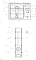
- FIG. 1 the cooking appliance 1 is shown in a highly schematic and simplified representation.
- the cooking appliance 1 has a cooking chamber 2, which is at least partially heated by steam at least one steam source 3.
- the vapor source 3, as in FIG. 1 indicated have multiple heat sources, which can be controlled individually or in total as needed.
- the vapor source 3 conducts the generated vapor 9 (see. FIG. 2 ) via steam inlet openings 4 to 7 in the cooking chamber 2 a.
- a central steam outlet opening 8 is connected to the environment 50 of the cooking appliance 1, so that the cooking appliance 1 or the steam cooking appliance 100 is designed as a system operating without pressure. Excess steam 9 can be removed from the interior of the cooking chamber 2 to the outside through the outlet opening 8 or air can be sucked in from the environment 50 if there is a negative pressure in the interior of the cooking chamber 2 if, for example, existing steam 9 condense there and not enough Steam 9 is replenished by the steam source 3. There may also be provided a plurality of steam outlet openings 8.
- FIG. 2 shows the common unit 10 in an enlarged view, on the rear wall 13 (see. Fig. 3 ) of the cooking chamber 2 is arranged interchangeable.
- the total of eight steam inlet openings 4 to 7 are provided here, which are arranged in pairs on four levels 14 to 17.
- two steam inlet openings 4, 5, 6 and 7 are provided in pairs on the assembly 10 and are formed so that the emerging from the steam inlet openings 4 to 7 steam 9 is directed in approximately opposite directions, as the drawn beam directions 45 at the steam inlet openings 7 show ,
- two steam inlet openings 4 to 7 are provided on each level 14 to 17.
- the steam outlet opening 8 is here arranged centrally between the lowest level 14 and the second lowest level 15 and thus between the steam inlet openings 4 and 5.
- a sensor device 31 Centrally within the steam outlet 8, a sensor device 31 is arranged, which comprises a temperature sensor 11.
- the arrangement of the temperature sensor 11 within the steam outlet opening 8 ensures that gas flowing through the steam outlet opening 8 at least partially impacts the temperature sensor 11, so that temperature changes caused by gas leakage or gas ingress can be detected quickly and reliably by the temperature sensor 11.
- FIG. 1 can be taken, between the levels 14, 15, 16 and 17, three cooking levels 25, 26 and 27 are provided. It is in FIG. 1 at the garden levels 25 and 27 each arranged as a Garblech Gar matterer 23 is arranged. The cooking container 23 is shown in dashed lines at the cooking levels 25 and 27. In addition, a corresponding Gar matterser 23 can be arranged at the Garebene 26.
- the arrangement of the cooking levels 25, 26 and 27 is such that each cooking level 25 to 27 can be acted upon by steam 9 of one or more steam sources 3 from above and below.
- the lowest cooking plane 25 is acted upon by steam from the steam inlet openings 4 and 5 and the cooking plane 26 is acted upon from below by steam 9 from the steam inlet openings 5 and from above by steam 9 from the steam inlet openings 6.
- the cooking plane 27 is again acted upon from above by steam 9 from the steam inlet openings 7 and from below by steam 9 from the steam inlet openings 6.
- Each cooking container 23 is here approximately trough-shaped and has a receiving edge 24 which rests on holders 28 of the cooking chamber 2.
- the holders 28 define the cooking levels 25-27 and support the cooking containers 23 downwardly.
- cooking appliance 1 is equipped with a control device 30, with control buttons 46 and a display 47 to output the operating state and / or the device program and other information.
- the vapor source 3 and the vapor sources 3 are connected via one or more vapor lines 29 to the respective steam inlet openings 4 to 7.
- the individual steam inlet openings 4 to 7 are each designed as a steam nozzle 18 in order to increase the flow velocity of the steam 9 discharged from the steam openings 4 to 7 and thus to improve the mixing with the cooking chamber atmosphere.
- the steam inlet openings 5, 6 and 7 are connected to each other via a common steam guide 22.
- the steam inlet openings 4 can be controlled separately. It is also possible that the steam inlet openings 5, 6 and 7 are each separately controllable.
- a light source 20 may be integrated in the cooking chamber 2 and in particular in the assembly 10.
- FIG. 3 shows a highly schematic cross section through the cooking appliance 1 after FIG. 1 , Clearly visible is the arranged on the rear wall 13 of the cooking chamber assembly 10th
- the steam outlet 8 is arranged, as it already Figures 1 and 2 was to be taken.
- the temperature sensor 11 is arranged here centrally in the steam outlet opening 8.
- the temperature sensor 11 (completely) within the cooking chamber 2 or (completely) outside of the cooking chamber 2 in example, the gap 44 can be arranged.
- the temperature sensor 11 is arranged inside the flow path 42 of the gas flow 43 through the steam outlet opening 8. Characterized in that the temperature sensor 11 is disposed within the flow path 42, the temperature sensor 11 is acted upon in each case with the passing through the steam outlet 8 gas stream 43.
- this gas stream 43 for example, at the outlet of excess steam has an elevated temperature or outside when the air is at a lower temperature than the oven temperature, the temperature sensor registers 11 such temperature changes directly. This allows a considerably finer control of the heating power and thus the cooking space temperature.
- the "breathing" of the cooking chamber 2 is largely avoided. In experiments it has been found that temporal and local temperature differences within the cooking chamber 2 are largely avoided and may even no longer be detected. Optically unsightly discolorations on foods are avoided.
- openings 55 are provided in the intermediate space 44.
- FIG. 4 is a highly schematic cross-section through the cooking chamber 2 of a cooking appliance 1 or Dampfgar réelles 100 approximately at the level of the steam outlet openings 7 just above the cooking plane 27 from FIG. 1 shown.
- the steam outlet openings 7 are arranged on the assembly 10 at the rear end of the cooking chamber 2 and have, as seen here in cross-section, constrictions 52 at the outlet cross section, so that the steam flow is accelerated at the exit from the steam inlet openings 7.
- the steam inlet openings 7 act as steam nozzles 18. This results in a particularly intensive mixing of the entering through the steam inlet openings 7 in the cooking chamber 2 steam 9 with the prevailing atmosphere there.
- the other steam inlet openings 4 to 6 are designed accordingly here.
- the steam flow 53 entering the cooking chamber 2 from the steam inlet openings 7 becomes approximately tangential, i. blown approximately parallel to the rear wall 13 in the cooking chamber 2, wherein a slight angle to the rear wall 13 may be present.
- the rear wall forms here a wall 54, at which the steam flow is guided along. Together with the cooking container 23 form the rear wall 13 and the side walls 54 steam channels 51, through which the incoming steam 9 is passed.
- the steam flow 53 takes the way along the rear wall back to the side wall, from there to the front end of the cooking chamber, there is again deflected and passes through the Garebene 27 back to the rear wall 13th
- FIG. 4 two different loads 40 and 41 are shown schematically on the cooking tray 23.
- FIG. 5 shows the temperature profile of two different loadings 40 and 41 over the time after the start of the cooking process. In both cases, it is first heated with the maximum steam output. The result is an approximate linear increase in temperature over time, with the increase being steeper at the lower load 40 than at the higher load 41. This is caused by the higher heat capacity of the higher load 41, as a larger heat capacity must be warmed up.
- a suitable temperature T1 is 40 degrees C
- a suitable temperature T2 may be 70 degrees C, for example.
- higher temperatures T1 e.g. 50 or 55 degrees C.
- a higher temperature T2 e.g. 75 or 80 degrees is possible.
- the period of time 48 or 48 a which is required until the characteristic temperature 12 in the cooking chamber has risen from the temperature T1 to the temperature T2, can be used to determine a measure 33 or 33a for the loading in the cooking chamber 2 , If necessary, the required time can also be used as a direct measure of the load. The greater the time span, the greater the load in the cooking chamber 2. This results in a clear manner from the illustration according to FIG. 5 already, that belonging to the period 48a Load 33a is less than the load associated with period 48.
- the local slope at one or more temperatures may also be used. to obtain a dimension 33 or 33a for the loading.
- the temporal temperature profile 34 or 34a depends on the load 40 or 41 and possibly different foods 21 and 21a.
- the heating power and thus the supplied amount of steam can be reduced to an excessive escape of steam from the cooking appliance 1 avoid.
- the reduced heating power is reflected directly in the lower slope of the temporal temperature curve 34a after the second temperature T2 and the temperature 38.
- the heating power can be further reduced, so that the intended cooking temperature is achieved without an excessive To remove the amount of steam from the cooking appliance.
- the heating power is reduced only upon reaching a predetermined or adjustable threshold temperature, e.g. 80 ° C can be.
- the heating power is preferably already reduced at a lower temperature 38, while at a higher load 41, the heating power is reduced only at a higher temperature 39.
- the temporal temperature profiles 34 and 34a result from the sensor signals 32 of the sensor device 31 and the temperature sensor 11.
- the temporal temperature profile 34 or 34a represents a direct measure of the respective heat capacity 37 of the contents of the cooking chamber 2.
- FIG. 6 is off for the example FIG. 5 in addition to the temporal temperature curves 34 and 34a also applied the corresponding heating power 36 and 36a.
- the rise in the FIG. 6 shown temperatures accordingly.
- the heating power can be considerably reduced until, when reaching the threshold temperature 35, the heating power is reduced again in order to continue the cooking process with reduced power.
- the temperature T2 can be used as the first threshold temperature 35a, while a second threshold temperature can still be provided near the intended cooking temperature 49.
- a high load 41 is first heated at the beginning of the cooking process with maximum heating power to bring as much steam 9 in the cooking chamber 2. Due to the slope of the temporal temperature curve 34 or the measure 33 determined therefrom for loading results that the maximum heating power can be continued until reaching a much higher threshold temperature 35, which may be close to the intended cooking temperature and, for example, only one, two , three or four degrees below the temperature of the silk. Only when the threshold temperature 35 is reached, the heating power is somewhat throttled and finally lowered again almost when the cooking temperature is reached, so that, for example, the cooking process continues with the same heating power as is the case with a low load 40.
- the heat output is adjusted in several stages or continuously. It is not necessary that the heating power is adjusted in only one, two or three stages. Also possible is a continuous or quasi-continuous adjustment of the heating power. It is also possible to provide two, three, four or five or more threshold temperatures at which the heating power is correspondingly reduced or increased.
- a cooking appliance 1 is provided by the cooking appliance according to the invention, which is easier to install, since the assembly 10 is ideally provided with all the process control elements. This makes it easier to manufacture and assemble. In addition, the customer gets the advantage that the device is easier to clean.
- a lighting element can be integrated into the assembly 10.
- a cost cooking device 1 which also meets the highest standards. Due to the design of the steam inlet openings 4 to 7 as a nozzle 18, the distribution of the steam 9 is further enhanced.
- the different controllable steam inlet openings at the different levels allow a more flexible control of the steam supply, which allows a high steam generator performance and despite the many steam inlet openings causes sufficient mixing.
- the steam outlet openings 8 in the lower region of the cooking chamber 2 cause the respective coolest region of the cooking chamber atmosphere to be discharged from the cooking chamber 2. Due to the inertia of the atmosphere, the relatively high inflow velocities of the steam 9 ensure a permanent movement within the cooking chamber 2 even after the inflow, which prevents segregation. As the steam introduced is warmer and lighter, it rises to the top while the heavier and colder air falls down. This achieves a more homogeneous temperature distribution, so that uneven or poor cooking results can be avoided.
- the heating phase is preferably heated in all cases with maximum steam capacity provided to keep the heating possible short.
- the heating times can be kept short both for large and for small loads without a significant amount of steam leaking from the device 1.
- the power is reduced in all cases, for example, only when the room temperature is greater than 80 degrees C. A rapid passage through the temperature range between 60 and 80 degrees reduces the enzymatic degradation of chlorophyll and thus reduces the risk of unsightly discoloration of the food.
- the arrangement of the temperature sensor 11 at the steam outlet 8 of the cooking chamber 2 allows a much better control, so that a "breathing" of the cooking chamber 2 can be significantly reduced and practically avoided altogether.
- a better cooking result can be ensured.
- the temperature sensor 11 positioned at the steam outlet opening 8 is located in the gas flow 43 passing through the steam outlet opening 8 and thus detects the hot exiting steam in the event of excess steam and the cold incoming air in the case of a lack of steam, which leads to a negative pressure in the cooking space, so very early can be counteracted accordingly.
- a sensitive adjustment of the heating power to the current conditions is achieved in the illustrated embodiment that virtually no temperature difference occurs after reaching the intended cooking temperature.
- the energy consumption is reduced because of the cooking chamber 2 exiting steam 9 is energetically high quality and must be replaced by a relatively large amount of heat, which is largely avoided here.
Landscapes
- Engineering & Computer Science (AREA)
- Chemical & Material Sciences (AREA)
- Combustion & Propulsion (AREA)
- Mechanical Engineering (AREA)
- General Engineering & Computer Science (AREA)
- Cookers (AREA)
Claims (11)
- Appareil de cuisson (1) comprenant au moins une chambre de cuisson (2), laquelle peut être chauffée par l'intermédiaire de vapeur (9) qui provient d'au moins une source de vapeur (3) ;
dans lequel plusieurs plans de cuisson (25-27) sont prévus dans la chambre de cuisson (2) en vue de la cuisson de plats (21) ;
dans lequel un guidage de la vapeur (22) est prévu, lequel comprend plusieurs ouvertures d'entrée de la vapeur (4-7) qui sont situées sur plusieurs plans d'entrée de la vapeur (14, 15, 16, 17), en vue de la répartition homogène de la vapeur (9) ;
caractérisé en ce que les ouvertures d'entrée de la vapeur (4-7) sont disposées par paires au niveau de l'une des parois (54) de la chambre de cuisson (2) et sont alignées en étant opposées les unes par rapport aux autres sur le plan latéral ;
dans lequel lesdites ouvertures d'entrée de la vapeur émettent la vapeur (9) le long d'au moins une paroi (54) de la chambre de cuisson (2) ;
dans lequel les ouvertures d'entrée de la vapeur (4-7) sont disposées de telle sorte que les plans de cuisson (25-27) peuvent être chauffés avec de la vapeur (9), respectivement par le dessus et par le bas, respectivement par l'intermédiaire d'au moins une ouverture d'entrée de la vapeur (4-7). - Appareil de cuisson (1) selon la revendication 1, caractérisé en ce que le guidage de la vapeur (22) comprend au moins une ouverture d'entrée de la vapeur (4) en vue du chauffage du plan de cuisson (25) par le bas et comprend au moins une ouverture d'entrée de la vapeur (5) en vue du chauffage du plan de cuisson (25) par le haut.
- Appareil de cuisson (1) selon la revendication 1 ou 2, caractérisé en ce que les ouvertures d'entrée de la vapeur (4-7) sont disposées au niveau de la paroi arrière (13) de la chambre de cuisson (2).
- Appareil de cuisson (1) selon l'une des revendications ci-dessus, caractérisé en ce qu'un récipient de cuisson (23) est prévu en vue d'y recevoir des plats (21), lequel peut être disposé au niveau du plan de cuisson (25-27).
- Appareil de cuisson (1) selon la revendication ci-dessus, caractérisé en ce que le récipient de cuisson (23) présente une bordure de réception (24) et est maintenu dans la chambre de cuisson (2) par des supports (28).
- Appareil de cuisson (1) selon l'une des revendications ci-dessus, caractérisé en ce que le récipient de cuisson (23) forme des conduites de vapeur dans la chambre de cuisson (2) en vue de la répartition de la vapeur.
- Appareil de cuisson (1) selon l'une des revendications ci-dessus, caractérisé en ce que les ouvertures d'entrée de la vapeur (4-7) sont conçues sous la forme de buses de vapeur (18).
- Appareil de cuisson (1) selon l'une des revendications ci-dessus, caractérisé en ce que les ouvertures d'entrée de la vapeur (4-7) peuvent être commandées séparément pour au moins deux plans de cuisson (25-27).
- Appareil de cuisson (1) selon l'une des revendications ci-dessus, caractérisé en ce que les ouvertures d'entrée de la vapeur (4-7) sont disposées par paires dans l'un des plans d'entrée de la vapeur (14, 15, 16, 17).
- Appareil de cuisson (1) selon l'une des revendications ci-dessus, caractérisé en ce qu'une ouverture de sortie de la vapeur (8) est disposée entre le plan d'entrée le plus bas de la vapeur (14) et le deuxième plan d'entrée le plus bas de la vapeur (15), laquelle ouverture relie la chambre de cuisson (2) avec l'environnement (50) de l'appareil de cuisson (1).
- Procédé destiné au fonctionnement d'un appareil de cuisson (1) selon l'une des revendications ci-dessus avec au moins une chambre de cuisson (2), laquelle est, pour l'essentiel, chauffée avec de la vapeur qui provient d'au moins une source de vapeur (3) ;
dans lequel au moins un plan de cuisson (25-27) est prévu dans la chambre de cuisson (2) en vue de la cuisson de plats (21) ;
caractérisé en ce que
la vapeur est émise à travers plusieurs plans d'entrée de la vapeur (14, 15, 16, 17) par des ouvertures d'entrée de la vapeur (4-7), le long d'au moins une paroi (54), de telle sorte qu'une répartition homogène de la vapeur et une alimentation de la vapeur vers le plan de cuisson (25-27) par le haut et par le bas sont réalisées.
Priority Applications (1)
| Application Number | Priority Date | Filing Date | Title |
|---|---|---|---|
| EP10401223.2A EP2469191B1 (fr) | 2010-12-23 | 2010-12-23 | Appareil de cuisson |
Applications Claiming Priority (1)
| Application Number | Priority Date | Filing Date | Title |
|---|---|---|---|
| EP10401223.2A EP2469191B1 (fr) | 2010-12-23 | 2010-12-23 | Appareil de cuisson |
Publications (2)
| Publication Number | Publication Date |
|---|---|
| EP2469191A1 EP2469191A1 (fr) | 2012-06-27 |
| EP2469191B1 true EP2469191B1 (fr) | 2017-08-30 |
Family
ID=44114371
Family Applications (1)
| Application Number | Title | Priority Date | Filing Date |
|---|---|---|---|
| EP10401223.2A Active EP2469191B1 (fr) | 2010-12-23 | 2010-12-23 | Appareil de cuisson |
Country Status (1)
| Country | Link |
|---|---|
| EP (1) | EP2469191B1 (fr) |
Cited By (1)
| Publication number | Priority date | Publication date | Assignee | Title |
|---|---|---|---|---|
| EP3628162B1 (fr) * | 2018-09-25 | 2025-03-26 | Miele & Cie. KG | Appareil de cuisson à fonction de cuisson à vapeur |
Families Citing this family (1)
| Publication number | Priority date | Publication date | Assignee | Title |
|---|---|---|---|---|
| DE102012112810A1 (de) * | 2012-12-20 | 2014-06-26 | Miele & Cie. Kg | Gargerät und Verfahren zum Betreiben eines Gargerätes |
Citations (1)
| Publication number | Priority date | Publication date | Assignee | Title |
|---|---|---|---|---|
| EP1538396A1 (fr) * | 2003-12-03 | 2005-06-08 | Samsung Electronics Co., Ltd. | Appareil de cuisson |
Family Cites Families (6)
| Publication number | Priority date | Publication date | Assignee | Title |
|---|---|---|---|---|
| DE10132581A1 (de) * | 2001-07-10 | 2003-01-30 | Imp Werke Ohg | Dampfgargerät |
| JP3737094B2 (ja) | 2004-01-07 | 2006-01-18 | シャープ株式会社 | 蒸気調理器 |
| US20070175884A1 (en) * | 2006-01-31 | 2007-08-02 | Atul Saksena | Steam cooker with steam delivery device |
| JP4106382B2 (ja) * | 2006-05-25 | 2008-06-25 | シャープ株式会社 | 加熱調理器 |
| EP2103878B1 (fr) * | 2008-03-20 | 2015-04-15 | Candy S.p.A. | Four de cuisson doté d'un dispositif d'humidification |
| DE102008051829A1 (de) * | 2008-10-17 | 2010-04-22 | Convotherm Elektrogeräte GmbH | Gargerät |
-
2010
- 2010-12-23 EP EP10401223.2A patent/EP2469191B1/fr active Active
Patent Citations (1)
| Publication number | Priority date | Publication date | Assignee | Title |
|---|---|---|---|---|
| EP1538396A1 (fr) * | 2003-12-03 | 2005-06-08 | Samsung Electronics Co., Ltd. | Appareil de cuisson |
Cited By (1)
| Publication number | Priority date | Publication date | Assignee | Title |
|---|---|---|---|---|
| EP3628162B1 (fr) * | 2018-09-25 | 2025-03-26 | Miele & Cie. KG | Appareil de cuisson à fonction de cuisson à vapeur |
Also Published As
| Publication number | Publication date |
|---|---|
| EP2469191A1 (fr) | 2012-06-27 |
Similar Documents
| Publication | Publication Date | Title |
|---|---|---|
| EP2610557A1 (fr) | Four de cuisson avec chauffage de la sole et de l'air chaud | |
| EP3034952A1 (fr) | Cuisiniere comprenant un compartiment de cuisson pouvant etre chauffe a l'aide d'une source de chauffage au gaz | |
| EP2469175B1 (fr) | Appareil de cuisson | |
| EP2468101B1 (fr) | Procédé d'utilisation d'un appareil de cuisson et un appareil de cuisson | |
| EP2469191A1 (fr) | Appareil de cuisson | |
| EP2745696B1 (fr) | Appareil de cuisson et procédé de fonctionnement d'un appareil de cuisson | |
| DE20104205U1 (de) | Heißlufttrockner für eine Beschichtungsanlage | |
| EP2468102B1 (fr) | Appareil de cuisson | |
| DE212013000201U1 (de) | Heißluft-Etagenofen | |
| DE2940300C2 (de) | Gasbeheiztes Kochgerät | |
| EP2716990B1 (fr) | Appareil plafonnier ou mural destiné à introduire de l'air refroidi ou réchauffé dans une pièce | |
| WO2008034765A1 (fr) | Four | |
| EP2573475B1 (fr) | Appareil d'aération conçu comme un appareil à induction ainsi que procédé de fonctionnement de cet appareil | |
| DE69206501T2 (de) | Infrarotstrahlungsbrenner für Glaskeramik-Kochmulde. | |
| EP3702684B1 (fr) | Climatisation des pièces comprenant une amenée d'air frais et thermorégulation | |
| EP3631785B1 (fr) | Bande lumineuse | |
| EP1334676B1 (fr) | Présentoir réfrigéré pour la présentation et la réfrigération de marchandises placées dans une enceinte réfrigérée | |
| DE102009021158A1 (de) | Infrarot-Heizung, insbesondere zum Beheizen von Hallen | |
| EP2072911A1 (fr) | Four à air chaud ou à circulation d'air | |
| DE1679192A1 (de) | Zyklothermofen | |
| DE3906969C2 (de) | Verfahren zur Regelung der Raumatmosphäre einer Dampfbadekabine | |
| DE10029355A1 (de) | Luftführungseinrichtung für Kühl- oder Warmluft in zu klimatisierenden Räumen zur Aufnahme zu klimatisierender Güter | |
| DE102006056063A1 (de) | Backofen und Betriebsverfahren für einen Backofen | |
| DE2163690C2 (de) | Sauna-Entlüftungsvorrichtung | |
| DE10054396A1 (de) | Backofen |
Legal Events
| Date | Code | Title | Description |
|---|---|---|---|
| AK | Designated contracting states |
Kind code of ref document: A1 Designated state(s): AL AT BE BG CH CY CZ DE DK EE ES FI FR GB GR HR HU IE IS IT LI LT LU LV MC MK MT NL NO PL PT RO RS SE SI SK SM TR |
|
| AX | Request for extension of the european patent |
Extension state: BA ME |
|
| PUAI | Public reference made under article 153(3) epc to a published international application that has entered the european phase |
Free format text: ORIGINAL CODE: 0009012 |
|
| 17P | Request for examination filed |
Effective date: 20121212 |
|
| 17Q | First examination report despatched |
Effective date: 20160919 |
|
| GRAP | Despatch of communication of intention to grant a patent |
Free format text: ORIGINAL CODE: EPIDOSNIGR1 |
|
| INTG | Intention to grant announced |
Effective date: 20170405 |
|
| GRAS | Grant fee paid |
Free format text: ORIGINAL CODE: EPIDOSNIGR3 |
|
| GRAA | (expected) grant |
Free format text: ORIGINAL CODE: 0009210 |
|
| AK | Designated contracting states |
Kind code of ref document: B1 Designated state(s): AL AT BE BG CH CY CZ DE DK EE ES FI FR GB GR HR HU IE IS IT LI LT LU LV MC MK MT NL NO PL PT RO RS SE SI SK SM TR |
|
| REG | Reference to a national code |
Ref country code: GB Ref legal event code: FG4D Free format text: NOT ENGLISH |
|
| REG | Reference to a national code |
Ref country code: CH Ref legal event code: EP |
|
| REG | Reference to a national code |
Ref country code: AT Ref legal event code: REF Ref document number: 923921 Country of ref document: AT Kind code of ref document: T Effective date: 20170915 |
|
| REG | Reference to a national code |
Ref country code: IE Ref legal event code: FG4D Free format text: LANGUAGE OF EP DOCUMENT: GERMAN |
|
| REG | Reference to a national code |
Ref country code: DE Ref legal event code: R096 Ref document number: 502010014079 Country of ref document: DE |
|
| REG | Reference to a national code |
Ref country code: FR Ref legal event code: PLFP Year of fee payment: 8 |
|
| REG | Reference to a national code |
Ref country code: NL Ref legal event code: MP Effective date: 20170830 |
|
| REG | Reference to a national code |
Ref country code: LT Ref legal event code: MG4D |
|
| PG25 | Lapsed in a contracting state [announced via postgrant information from national office to epo] |
Ref country code: FI Free format text: LAPSE BECAUSE OF FAILURE TO SUBMIT A TRANSLATION OF THE DESCRIPTION OR TO PAY THE FEE WITHIN THE PRESCRIBED TIME-LIMIT Effective date: 20170830 Ref country code: LT Free format text: LAPSE BECAUSE OF FAILURE TO SUBMIT A TRANSLATION OF THE DESCRIPTION OR TO PAY THE FEE WITHIN THE PRESCRIBED TIME-LIMIT Effective date: 20170830 Ref country code: SE Free format text: LAPSE BECAUSE OF FAILURE TO SUBMIT A TRANSLATION OF THE DESCRIPTION OR TO PAY THE FEE WITHIN THE PRESCRIBED TIME-LIMIT Effective date: 20170830 Ref country code: HR Free format text: LAPSE BECAUSE OF FAILURE TO SUBMIT A TRANSLATION OF THE DESCRIPTION OR TO PAY THE FEE WITHIN THE PRESCRIBED TIME-LIMIT Effective date: 20170830 Ref country code: NO Free format text: LAPSE BECAUSE OF FAILURE TO SUBMIT A TRANSLATION OF THE DESCRIPTION OR TO PAY THE FEE WITHIN THE PRESCRIBED TIME-LIMIT Effective date: 20171130 |
|
| PG25 | Lapsed in a contracting state [announced via postgrant information from national office to epo] |
Ref country code: ES Free format text: LAPSE BECAUSE OF FAILURE TO SUBMIT A TRANSLATION OF THE DESCRIPTION OR TO PAY THE FEE WITHIN THE PRESCRIBED TIME-LIMIT Effective date: 20170830 Ref country code: BG Free format text: LAPSE BECAUSE OF FAILURE TO SUBMIT A TRANSLATION OF THE DESCRIPTION OR TO PAY THE FEE WITHIN THE PRESCRIBED TIME-LIMIT Effective date: 20171130 Ref country code: RS Free format text: LAPSE BECAUSE OF FAILURE TO SUBMIT A TRANSLATION OF THE DESCRIPTION OR TO PAY THE FEE WITHIN THE PRESCRIBED TIME-LIMIT Effective date: 20170830 Ref country code: GR Free format text: LAPSE BECAUSE OF FAILURE TO SUBMIT A TRANSLATION OF THE DESCRIPTION OR TO PAY THE FEE WITHIN THE PRESCRIBED TIME-LIMIT Effective date: 20171201 Ref country code: IS Free format text: LAPSE BECAUSE OF FAILURE TO SUBMIT A TRANSLATION OF THE DESCRIPTION OR TO PAY THE FEE WITHIN THE PRESCRIBED TIME-LIMIT Effective date: 20171230 Ref country code: LV Free format text: LAPSE BECAUSE OF FAILURE TO SUBMIT A TRANSLATION OF THE DESCRIPTION OR TO PAY THE FEE WITHIN THE PRESCRIBED TIME-LIMIT Effective date: 20170830 |
|
| PG25 | Lapsed in a contracting state [announced via postgrant information from national office to epo] |
Ref country code: NL Free format text: LAPSE BECAUSE OF FAILURE TO SUBMIT A TRANSLATION OF THE DESCRIPTION OR TO PAY THE FEE WITHIN THE PRESCRIBED TIME-LIMIT Effective date: 20170830 |
|
| PG25 | Lapsed in a contracting state [announced via postgrant information from national office to epo] |
Ref country code: RO Free format text: LAPSE BECAUSE OF FAILURE TO SUBMIT A TRANSLATION OF THE DESCRIPTION OR TO PAY THE FEE WITHIN THE PRESCRIBED TIME-LIMIT Effective date: 20170830 Ref country code: DK Free format text: LAPSE BECAUSE OF FAILURE TO SUBMIT A TRANSLATION OF THE DESCRIPTION OR TO PAY THE FEE WITHIN THE PRESCRIBED TIME-LIMIT Effective date: 20170830 Ref country code: CZ Free format text: LAPSE BECAUSE OF FAILURE TO SUBMIT A TRANSLATION OF THE DESCRIPTION OR TO PAY THE FEE WITHIN THE PRESCRIBED TIME-LIMIT Effective date: 20170830 Ref country code: PL Free format text: LAPSE BECAUSE OF FAILURE TO SUBMIT A TRANSLATION OF THE DESCRIPTION OR TO PAY THE FEE WITHIN THE PRESCRIBED TIME-LIMIT Effective date: 20170830 |
|
| PG25 | Lapsed in a contracting state [announced via postgrant information from national office to epo] |
Ref country code: EE Free format text: LAPSE BECAUSE OF FAILURE TO SUBMIT A TRANSLATION OF THE DESCRIPTION OR TO PAY THE FEE WITHIN THE PRESCRIBED TIME-LIMIT Effective date: 20170830 Ref country code: IT Free format text: LAPSE BECAUSE OF FAILURE TO SUBMIT A TRANSLATION OF THE DESCRIPTION OR TO PAY THE FEE WITHIN THE PRESCRIBED TIME-LIMIT Effective date: 20170830 Ref country code: SM Free format text: LAPSE BECAUSE OF FAILURE TO SUBMIT A TRANSLATION OF THE DESCRIPTION OR TO PAY THE FEE WITHIN THE PRESCRIBED TIME-LIMIT Effective date: 20170830 Ref country code: SK Free format text: LAPSE BECAUSE OF FAILURE TO SUBMIT A TRANSLATION OF THE DESCRIPTION OR TO PAY THE FEE WITHIN THE PRESCRIBED TIME-LIMIT Effective date: 20170830 |
|
| REG | Reference to a national code |
Ref country code: DE Ref legal event code: R097 Ref document number: 502010014079 Country of ref document: DE |
|
| PLBE | No opposition filed within time limit |
Free format text: ORIGINAL CODE: 0009261 |
|
| STAA | Information on the status of an ep patent application or granted ep patent |
Free format text: STATUS: NO OPPOSITION FILED WITHIN TIME LIMIT |
|
| REG | Reference to a national code |
Ref country code: CH Ref legal event code: PL |
|
| 26N | No opposition filed |
Effective date: 20180531 |
|
| GBPC | Gb: european patent ceased through non-payment of renewal fee |
Effective date: 20171223 |
|
| PG25 | Lapsed in a contracting state [announced via postgrant information from national office to epo] |
Ref country code: SI Free format text: LAPSE BECAUSE OF FAILURE TO SUBMIT A TRANSLATION OF THE DESCRIPTION OR TO PAY THE FEE WITHIN THE PRESCRIBED TIME-LIMIT Effective date: 20170830 |
|
| REG | Reference to a national code |
Ref country code: IE Ref legal event code: MM4A |
|
| PG25 | Lapsed in a contracting state [announced via postgrant information from national office to epo] |
Ref country code: LU Free format text: LAPSE BECAUSE OF NON-PAYMENT OF DUE FEES Effective date: 20171223 Ref country code: MT Free format text: LAPSE BECAUSE OF FAILURE TO SUBMIT A TRANSLATION OF THE DESCRIPTION OR TO PAY THE FEE WITHIN THE PRESCRIBED TIME-LIMIT Effective date: 20170830 |
|
| REG | Reference to a national code |
Ref country code: BE Ref legal event code: MM Effective date: 20171231 |
|
| PG25 | Lapsed in a contracting state [announced via postgrant information from national office to epo] |
Ref country code: IE Free format text: LAPSE BECAUSE OF NON-PAYMENT OF DUE FEES Effective date: 20171223 |
|
| PG25 | Lapsed in a contracting state [announced via postgrant information from national office to epo] |
Ref country code: CH Free format text: LAPSE BECAUSE OF NON-PAYMENT OF DUE FEES Effective date: 20171231 Ref country code: BE Free format text: LAPSE BECAUSE OF NON-PAYMENT OF DUE FEES Effective date: 20171231 Ref country code: LI Free format text: LAPSE BECAUSE OF NON-PAYMENT OF DUE FEES Effective date: 20171231 Ref country code: GB Free format text: LAPSE BECAUSE OF NON-PAYMENT OF DUE FEES Effective date: 20171223 |
|
| PG25 | Lapsed in a contracting state [announced via postgrant information from national office to epo] |
Ref country code: HU Free format text: LAPSE BECAUSE OF FAILURE TO SUBMIT A TRANSLATION OF THE DESCRIPTION OR TO PAY THE FEE WITHIN THE PRESCRIBED TIME-LIMIT; INVALID AB INITIO Effective date: 20101223 Ref country code: MC Free format text: LAPSE BECAUSE OF FAILURE TO SUBMIT A TRANSLATION OF THE DESCRIPTION OR TO PAY THE FEE WITHIN THE PRESCRIBED TIME-LIMIT Effective date: 20170830 |
|
| REG | Reference to a national code |
Ref country code: DE Ref legal event code: R084 Ref document number: 502010014079 Country of ref document: DE |
|
| PG25 | Lapsed in a contracting state [announced via postgrant information from national office to epo] |
Ref country code: CY Free format text: LAPSE BECAUSE OF NON-PAYMENT OF DUE FEES Effective date: 20170830 |
|
| PG25 | Lapsed in a contracting state [announced via postgrant information from national office to epo] |
Ref country code: MK Free format text: LAPSE BECAUSE OF FAILURE TO SUBMIT A TRANSLATION OF THE DESCRIPTION OR TO PAY THE FEE WITHIN THE PRESCRIBED TIME-LIMIT Effective date: 20170830 |
|
| PG25 | Lapsed in a contracting state [announced via postgrant information from national office to epo] |
Ref country code: TR Free format text: LAPSE BECAUSE OF FAILURE TO SUBMIT A TRANSLATION OF THE DESCRIPTION OR TO PAY THE FEE WITHIN THE PRESCRIBED TIME-LIMIT Effective date: 20170830 |
|
| PG25 | Lapsed in a contracting state [announced via postgrant information from national office to epo] |
Ref country code: PT Free format text: LAPSE BECAUSE OF FAILURE TO SUBMIT A TRANSLATION OF THE DESCRIPTION OR TO PAY THE FEE WITHIN THE PRESCRIBED TIME-LIMIT Effective date: 20170830 |
|
| PG25 | Lapsed in a contracting state [announced via postgrant information from national office to epo] |
Ref country code: AL Free format text: LAPSE BECAUSE OF FAILURE TO SUBMIT A TRANSLATION OF THE DESCRIPTION OR TO PAY THE FEE WITHIN THE PRESCRIBED TIME-LIMIT Effective date: 20170830 |
|
| PGFP | Annual fee paid to national office [announced via postgrant information from national office to epo] |
Ref country code: AT Payment date: 20221221 Year of fee payment: 13 |
|
| P01 | Opt-out of the competence of the unified patent court (upc) registered |
Effective date: 20230529 |
|
| PGFP | Annual fee paid to national office [announced via postgrant information from national office to epo] |
Ref country code: FR Payment date: 20231226 Year of fee payment: 14 |
|
| REG | Reference to a national code |
Ref country code: AT Ref legal event code: MM01 Ref document number: 923921 Country of ref document: AT Kind code of ref document: T Effective date: 20231223 |
|
| PG25 | Lapsed in a contracting state [announced via postgrant information from national office to epo] |
Ref country code: AT Free format text: LAPSE BECAUSE OF NON-PAYMENT OF DUE FEES Effective date: 20231223 |
|
| PG25 | Lapsed in a contracting state [announced via postgrant information from national office to epo] |
Ref country code: AT Free format text: LAPSE BECAUSE OF NON-PAYMENT OF DUE FEES Effective date: 20231223 |
|
| PG25 | Lapsed in a contracting state [announced via postgrant information from national office to epo] |
Ref country code: FR Free format text: LAPSE BECAUSE OF NON-PAYMENT OF DUE FEES Effective date: 20241231 |
|
| PGFP | Annual fee paid to national office [announced via postgrant information from national office to epo] |
Ref country code: DE Payment date: 20251231 Year of fee payment: 16 |