EP2469317A2 - Télescope doté d'un objectif et d'un module oculaire - Google Patents
Télescope doté d'un objectif et d'un module oculaire Download PDFInfo
- Publication number
- EP2469317A2 EP2469317A2 EP11195243A EP11195243A EP2469317A2 EP 2469317 A2 EP2469317 A2 EP 2469317A2 EP 11195243 A EP11195243 A EP 11195243A EP 11195243 A EP11195243 A EP 11195243A EP 2469317 A2 EP2469317 A2 EP 2469317A2
- Authority
- EP
- European Patent Office
- Prior art keywords
- module
- eyepiece
- telescope according
- telescope
- connection
- Prior art date
- Legal status (The legal status is an assumption and is not a legal conclusion. Google has not performed a legal analysis and makes no representation as to the accuracy of the status listed.)
- Granted
Links
Images
Classifications
-
- G—PHYSICS
- G02—OPTICS
- G02B—OPTICAL ELEMENTS, SYSTEMS OR APPARATUS
- G02B23/00—Telescopes, e.g. binoculars; Periscopes; Instruments for viewing the inside of hollow bodies; Viewfinders; Optical aiming or sighting devices
-
- G—PHYSICS
- G02—OPTICS
- G02B—OPTICAL ELEMENTS, SYSTEMS OR APPARATUS
- G02B7/00—Mountings, adjusting means, or light-tight connections, for optical elements
- G02B7/02—Mountings, adjusting means, or light-tight connections, for optical elements for lenses
- G02B7/04—Mountings, adjusting means, or light-tight connections, for optical elements for lenses with mechanism for focusing or varying magnification
- G02B7/10—Mountings, adjusting means, or light-tight connections, for optical elements for lenses with mechanism for focusing or varying magnification by relative axial movement of several lenses, e.g. of varifocal objective lens
Definitions
- the invention relates to a telescope, which is composed of interconnectable modules, wherein the telescope consists of at least a lens module and an eyepiece and the lens module and the eyepiece each have a connection interface for connecting the modules.
- the known embodiment has an objective and an image utilization unit, for example in the form of a photographic camera, which can be used instead of an eyepiece.
- an image utilization unit for example in the form of a photographic camera, which can be used instead of an eyepiece.
- a focusing device is provided, wherein between the lens and the focusing device, a central unit is arranged.
- the image utilization unit is attached to the focusing device with a replaceable module unit.
- This object is achieved with a telescope of the type mentioned in the present invention, that in the eyepiece module, an eyepiece and a unit for changing the magnification and a unit for image reversal are integrated.
- zoom and “magnification change” or “mutable magnification” are used interchangeably, as are the terms “focus” and “focus” in this document.
- the eyepiece and the unit for changing the magnification can be designed as a common unit.
- the unit for image reversal can be designed as a prism system.
- the unit for changing the magnification and the unit for image reversal can be designed as a common unit.
- a variant of the invention which allows a very short design, provides that the common unit to change the magnification and image reversal as a lens system is executed, which images an image in a first intermediate image plane with a variable scale and vice versa in a second intermediate image plane.
- At least one reticle can be arranged at the location of at least one intermediate image plane.
- the telescope can have at least one adjusting means for focusing and at least one adjusting means for varying the magnification.
- the at least one adjusting means for varying the magnification can be arranged according to an advantageous variant of the invention on the lens module or on the eyepiece module, in which case the at least one adjusting means for focusing on the lens module or the eyepiece module can be arranged.
- At least one of the adjusting means can be arranged in the region of one of the connection interfaces.
- the operability and handling of the telescope can be further improved by arranging one of the adjusting means on the lens module in the region of the connection interface of the objective module and the other of the adjusting means on the eyepiece module in the region of the connection interface of the eyepiece module.
- An embodiment of the invention which is characterized by a particularly good operability, provides that the adjusting means are designed as adjusting rings whose end faces lie in parallel to a separation / connection plane of the lens module and the eyepiece module levels.
- the use of mutually parallel collars allows one-handed adjustment of the telescope.
- a particularly advantageous embodiment of the invention provides that the adjusting means are at least partially in a parting plane of the connection interfaces. This allows a spatially particularly close arrangement of the actuating means to each other, whereby the handling is further facilitated. Become the eyepiece and lens module directly with each other connected, the adjusting means are in a parting plane of the connection interfaces of the eyepiece and lens module, so that the adjusting means according to this embodiment may be immediately adjacent to each other.
- a bayonet closure can each be formed by two connection interfaces which interact directly with one another.
- This embodiment enables a particularly simple connection of the modules. It should be noted that in the present context, a bayonet closure any kind of plug / screw cap is understood.
- two directly interacting connection interface can form a plug connection which can be released from one another by axial displacement, at least one retaining element cooperating with at least one actuating element and connecting the connection interfaces being forced back into a release position for release.
- This variant of the invention allows a very simple connection of the individual modules, since this only a translational movement of the connection interfaces is required.
- a further variant of the invention provides that two connection interfaces which interact directly with one another can be screwed together.
- connection interfaces each have a surface profile deviating from a flat shape, wherein a connection interface at least partially in the form of a male part and the other interface is at least partially formed as a female part ,
- connection interfaces Proper connection of the modules to each other can be monitored by arranging at least one switch on at least one of the connection interfaces, which switch is actuated when the connection interfaces are correctly connected.
- a plurality of switches are provided, wherein in a connected state of the connection interfaces a predeterminable combination of the switches is actuated, wherein an electrical contact between the lens module and the eyepiece module and / or a data connection between the lens module and the eyepiece module is made only upon actuation of the switch in the predetermined combination.
- switches are designed as reed switch contacts.
- the switches need not be arranged on the surface of the connection interfaces and are therefore invisible from the outside.
- the switches cooperating mating surfaces of the other connection interface can be equipped with corresponding magnets, preferably permanent magnets.
- two directly interacting joints can form a reed relay.
- a particularly advantageous variant of the invention provides, which is characterized by a variety of applications, provides that the eyepiece is a multifunction module, which further functionalities, in particular a distance measuring function, a photo function, video or night vision function has.
- the further functionalities are realized using the viewing channel of the objective module. This has the advantage, among other things, that information can also be faded into the optical beam path and displayed by the user. In addition, this solution can also achieve a very compact design.
- a further variant of the invention provides that an eyepiece optics is permanently integrated into the eyepiece module.
- the structure of the eyepiece module can be simplified. For a better understanding of the invention, this will be explained in more detail with reference to the following figures.
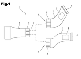
- a telescope 1 according to the invention has a lens module 2 and an eyepiece module 3.
- two different eyepiece modules 3 are shown, which can alternatively be connected to the lens module 2.
- the objective module 2 and the eyepiece module 3 in turn each have a connection interface 4, 5 for connecting the modules 2, 3.
- the variant of the invention shown here shows a telescope 1 with a monocular, however, instead of an eyepiece module 3 with only one eyepiece, an eyepiece module 3 with a binocular can also be used.
- a prism portion and further optical components can be arranged in the eyepiece module.
- a unit 6 for image reversal and an eyepiece 7 with variable magnification can be integrated in the eyepiece module 3.
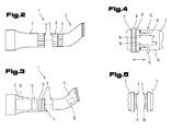
- an optics or unit for changing the magnification can be integrated in the lens module 2, as in Fig. 3 shown.
- this optics or unit is provided with the reference numeral 10.
- the eyepiece 7 and the magnification changing unit 10 may be implemented as a common unit.
- the unit 10 can also serve for image reversal and can be designed, for example, as a prism system.
- the magnification changing unit 10 and the image reversing unit 6 may also be implemented as a common unit.
- the common unit for changing the magnification and for the image reversal can also be embodied as a lens system which images an image in a first intermediate image plane with a variable scale and vice versa into a second intermediate image plane.
- At the locations of the intermediate image planes can each be arranged a reticle. It is also possible that only at the location of an intermediate image plane a reticle is arranged (see also in the FIGS. 7 to 9 illustrated embodiments).
- the objective module 2 can have an adjusting means 8 for zooming and the eyepiece module 3 can have an adjusting means 9 for focusing in the region of its connection interface 5.
- the means for zooming or focusing are arranged reversed.
- the adjusting means 8, 9 are both arranged on the eyepiece module 2, as shown in FIG Fig. 2 is shown. This may be particularly advantageous if the eyepiece module 3 has an eyepiece for zooming and focusing.
- the adjusting means 8 and 9 can also be arranged on the objective module 2. This is particularly advantageous if in the lens module 2, an optics 10 for changing the magnification and an optics 11 are integrated for focusing or focusing. In this variant of the invention, it is particularly advantageous if the eyepiece optics is permanently integrated into the eyepiece module 3.
- the adjusting means 8, 9 may be formed as adjusting rings whose end faces are in parallel to a separation / connection plane of the lens module 2 and the eyepiece module 3 levels. As can be seen further from the illustrations, the adjusting means 8, 9 can lie, at least in sections, in a parting plane of the connection interfaces 4, 5. Even if the adjusting means 8 and 9 shown here are designed as collars, it should be noted at this point that the adjusting means 8 and 9 can also be designed as actuation buttons or buttons.
- the eyepiece module 3 may be formed as a multifunction module and have additional functions.
- the eyepiece module 3 for example, as a video recorder, digital camera low-light amplifier, infrared lighting, rangefinder, module for optical signal recording, module for insertion of information and data in the visual beam path, module for image stabilization, etc. be formed ..
- the other functionalities are realized using the viewing channel of the lens module.
- the eyepiece module 3 is a unit 12 for the insertion of additional data, in particular geographic data, which relate to the current location is formed.
- the eyepiece module 3 or the telescope 1 can have a receiver of a position-finding system, for example of the GPS system. Based on the current position data stored in a database information can be displayed. For this purpose, value ranges of geoposition data can be assigned specific information.
- the database can be stored in a memory of the telescope 1 or of the eyepiece module 3 or stored in a contactable via a wireless network server. If the database can be queried via a radio network, for example the GSM network, the telescope 1 or the eyepiece module 3 can be equipped with a corresponding communication module.
- an electronic compass can be arranged in the telescope 1 or in the eyepiece module 3. Based on the data of the electronic compass can be determined in which direction the lens of the telescope 1 is held. The determined geographical location of the telescope 1 and the viewing direction of the telescope 1 can then be used as selection criteria for the insertion of data. For example, names of mountains or other geographical objects can be displayed.
- a selection of the information to be displayed can also be invoked on the basis of a menu displayed in a beam path or displayed on an external screen, which can conveniently be called by an externally accessible actuating element, such as a switch arranged on the telescope 1 or the eyepiece module 3 or a setting wheel ,
- the telescope 1 may have an extension for insertion into a corresponding shoe of a tripod.
- connection interfaces 4, 5 each a bayonet closure.
- connection interfaces 4, 5 can alternatively be screwed together to form a bayonet closure, wherein the connection interfaces may in this case have mutually corresponding screw threads.
- two directly cooperating connection interfaces 13, 14 also form a plug connection, which can be achieved by axial displacement.
- one or more holding elements 16 cooperating with one or more corresponding actuating elements 15 can be pushed back into a release position.
- the holding elements 16 may be spring-loaded Be formed locking lugs.
- the actuating elements 15, which may be formed as extensions of the holding elements 16 the holding elements 16 can be brought out of engagement with corresponding recesses of the connection interface 13. If the actuators are not activated, the holding elements are moved by the spring force in the direction of the connection interface 13.
- the holding elements 16 may be arranged on the outer connection interface 14.
- connection interfaces 13, 14 When dissolved holding elements 16, ie with activated actuators 15, the connection interfaces 13, 14 are moved in the axial direction against each other.
- the shift direction is in Fig. 4 indicated by a double arrow. It should be noted at this point, however, that there are many other solutions not explicitly mentioned here, which allow a coupling of the connection interfaces 13, 14 by axial displacement.
- connection interfaces 13 and 14 may each have a deviating from a flat shape frontal surface profile.
- a connection interface 13 may be formed in sections in the form of a male part and the other connection interface 14 in sections as a female part.
- one or more switches 17, which are actuated when the connection interfaces 4, 5 are correctly connected, may be arranged on one of the connection interfaces 4, 5.
- a control signal can be generated, which signals on an output unit, for example an LED, a correct connection of the connection interfaces 4 and 5.
- switches 17 are preferably designed as reed switch contacts.
- magnets 18 may be arranged at positions of the connection interfaces 4, 5 cooperating with the switches 17.
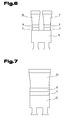
- the eyepiece module 19 may be formed as a binocular.
- two objective modules 20, 21 or a lens module with two objectives can also be used in this case.
- a binocular 22 with a single lens module 23 it is how in Fig. 7 also possible to use a binocular 22 with a single lens module 23.
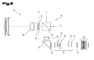
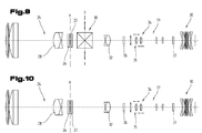
- Fig. 8 shows by way of example a first optical structure of a telescope according to the invention.
- the objective module 24 and the eyepiece module 25 can be separated from one another in a parting plane e or are connected to one another via their connection interfaces in the parting plane e.
- the lens module 24 may comprise an adjustable lens 28, which serves for focusing and can be actuated by means of an adjusting means for focusing, for example one of the above-mentioned adjusting means for focusing.
- the objective module 24 and the eyepiece module 25 can have glass covers 26, 27.
- the separation of the two modules takes place between the two glass covers 27, wherein the connection interfaces, for example, the bayonet closure forming connection interfaces between the two glass covers 27 may be arranged.
- the telescope according to the invention can, as in Fig. 8 shown to have an offset.
- the telescope according to the invention as in the FIGS. 9 and 10 shown, is straight.
- the eyepiece module can have a prism 29, with which information or other optical objects, such as infrared rays etc., can be coupled in or out in the direction of the objective.
- information or other optical objects such as infrared rays etc.
- the input or output direction of the lens is in Fig. 8 denoted by the reference I.
- a deflection prism 31 may be provided in order to deflect the beam emerging from the prism 29 in the direction of the eyepiece 30.
- the coupling and decoupling can of course also be carried out in the same way in the case of the second prism 31 or also in the case of both prisms 29 and 31.
- a lens 32 may be provided for image correction.
- the lens 32 is not necessarily required in the illustrated embodiment.
- the telescope according to the invention may have a lens reversing system 33.
- the lens inverting system 33 may include, for example, two movable lens groups 34 and 35 included in FIG Fig. 8 are shown in two different zoom positions.
- the movable lens groups 34 and 35 may be operated by zooming control means such as one of the above-mentioned zooming control means.
- reticles 36 and 37 may be arranged.
- lens groups are only examples and represent only one of several possible embodiments.
- Planar mirrors could also be used instead of the prisms.
- the telescope according to the invention can also have a straight construction.
- coupling or uncoupling of optical objects for example information in the form of images, or electromagnetic waves, for example from the infrared range, etc., in the direction of the objective 24 or the eyepiece 30 can also take place by means of a single prism 38.
Landscapes
- Physics & Mathematics (AREA)
- General Physics & Mathematics (AREA)
- Optics & Photonics (AREA)
- Astronomy & Astrophysics (AREA)
- Telescopes (AREA)
Applications Claiming Priority (1)
| Application Number | Priority Date | Filing Date | Title |
|---|---|---|---|
| ATA2131/2010A AT510935B1 (de) | 2010-12-23 | 2010-12-23 | Teleskop mit objektiv und okularmodul |
Publications (3)
| Publication Number | Publication Date |
|---|---|
| EP2469317A2 true EP2469317A2 (fr) | 2012-06-27 |
| EP2469317A3 EP2469317A3 (fr) | 2012-08-29 |
| EP2469317B1 EP2469317B1 (fr) | 2018-07-25 |
Family
ID=45440286
Family Applications (1)
| Application Number | Title | Priority Date | Filing Date |
|---|---|---|---|
| EP11195243.8A Active EP2469317B1 (fr) | 2010-12-23 | 2011-12-22 | Télescope doté d'un objectif et d'un module oculaire |
Country Status (5)
| Country | Link |
|---|---|
| US (1) | US10365469B2 (fr) |
| EP (1) | EP2469317B1 (fr) |
| CN (1) | CN102566037B (fr) |
| AT (1) | AT510935B1 (fr) |
| DE (1) | DE102011056757A1 (fr) |
Families Citing this family (5)
| Publication number | Priority date | Publication date | Assignee | Title |
|---|---|---|---|---|
| AT510937B1 (de) | 2010-12-23 | 2021-02-15 | Swarovski Optik Kg | Modulares teleskop |
| AT510935B1 (de) | 2010-12-23 | 2021-02-15 | Swarovski Optik Kg | Teleskop mit objektiv und okularmodul |
| AT510936B1 (de) * | 2010-12-23 | 2021-02-15 | Swarovski Optik Kg | Teleskop mit miteinander verbindbaren modulen |
| DE102015102319B3 (de) | 2015-02-18 | 2016-05-25 | Leica Camera Ag | Schnittweiten-Extender für teleskopische Abbildungssysteme |
| EP3969955A4 (fr) | 2019-05-13 | 2023-01-25 | Maranon, Inc. | Dispositifs optiques à base électro-optique |
Citations (1)
| Publication number | Priority date | Publication date | Assignee | Title |
|---|---|---|---|---|
| DE9408059U1 (de) | 1994-05-16 | 1995-09-14 | Strauß, Peter, Dipl.-Ing., 91217 Hersbruck | Spektiv als Baukastensystem |
Family Cites Families (67)
| Publication number | Priority date | Publication date | Assignee | Title |
|---|---|---|---|---|
| US2662443A (en) * | 1951-08-27 | 1953-12-15 | W & L E Gurley | Erecting eyepiece with variable magnification |
| US3504965A (en) | 1966-04-28 | 1970-04-07 | Argus Inc | Portable motion picture camera |
| US3981021A (en) | 1975-06-27 | 1976-09-14 | Beecher William J | Binocular adapter for a camera having a recessed lens |
| DE7602798U1 (de) | 1976-02-02 | 1976-07-29 | Lauterbach, Heinz, 8990 Lindau | Prismenansatz mit adapter fuer fotoobjektive, |
| JPS5323646A (en) * | 1976-08-18 | 1978-03-04 | Raito Kouki Seisakushiyo Kk | Biaxial zoom binoculars |
| JPS54133355A (en) * | 1978-04-07 | 1979-10-17 | Nippon Chemical Ind | Erect type zoom telephoto optical system |
| US4302077A (en) | 1978-09-29 | 1981-11-24 | Canon Kabushiki Kaisha | Bayonet device for lens barrel |
| JPS55103611U (fr) * | 1979-01-12 | 1980-07-19 | ||
| US4249799A (en) | 1979-04-27 | 1981-02-10 | The Iglesias Trust | Connector for optical devices |
| JPS57196206A (en) | 1981-05-29 | 1982-12-02 | Hoya Corp | Autofocus binocular |
| JPS5865013U (ja) * | 1981-10-28 | 1983-05-02 | 株式会社ライト光機製作所 | ズ−ム単眼鏡 |
| DE3208814C2 (de) * | 1982-03-11 | 1985-04-18 | D. Swarovski & Co., Wattens, Tirol | Zielfernrohr |
| US4676593A (en) * | 1983-04-18 | 1987-06-30 | Asahi Kogaku Kogyo Kabushiki Kaisha | Eyepiece and photographing device for fiberscope |
| US4600277A (en) * | 1984-02-13 | 1986-07-15 | Murray Jr Joseph E | Telescope with multiple image-viewing assemblies |
| US4746990A (en) | 1985-12-02 | 1988-05-24 | Olympus Optical Co., Ltd. | Detachable unit electronic camera |
| US5053794A (en) | 1989-12-08 | 1991-10-01 | Benz William G | Universal adapter for attaching a camera to associated optical devices such as telescopes, microscopes and the like |
| US5079646A (en) * | 1990-07-09 | 1992-01-07 | Applied Laser Systems, Inc. | Optical coupling device |
| US5305142A (en) | 1992-03-06 | 1994-04-19 | Itt Corporation | Replacement assembly for an image intensifier tube |
| DE4231655C5 (de) * | 1992-09-22 | 2006-01-26 | Leica Camera Ag | Monokulares Fernrohr konstanter Länge |
| DE69429872T2 (de) | 1993-11-12 | 2002-10-02 | Itt Manufacturing Enterprises, Inc. | Monokulare nachtsichtvorrichtung |
| WO1996010764A1 (fr) | 1994-09-30 | 1996-04-11 | International Standard Electric Corp. | Ensemble collimateur/dioptre a systeme a trajet optique replie pour dispositif de vision nocture monoculaire |
| JP2795191B2 (ja) | 1994-10-04 | 1998-09-10 | 株式会社デンソー | El表示装置の駆動装置 |
| EP0815483A4 (fr) | 1995-03-16 | 1998-06-03 | Itt Mfg Enterprises Inc | Dispositif de vision de nuit compact |
| JP2995648B2 (ja) | 1995-06-05 | 1999-12-27 | 株式会社ハッコー商事 | 照準望遠鏡 |
| US5604630A (en) | 1995-06-30 | 1997-02-18 | Itt Corporation | Night vision monocular with balanced optics |
| US5867313A (en) | 1995-07-31 | 1999-02-02 | Itt Corporation | Multipurpose night vision monocular |
| US5737119A (en) | 1995-09-06 | 1998-04-07 | Hughes Electronics | Thermal imaging device |
| JP3503911B2 (ja) | 1995-09-12 | 2004-03-08 | 富士写真光機株式会社 | 接眼ズームレンズ系 |
| US5644425A (en) | 1995-11-14 | 1997-07-01 | Itt Corporation | Night Vision Monocular with unistructural optical bed |
| US5877892A (en) | 1996-04-01 | 1999-03-02 | Asahi Seimitsu Kabushiki Kaisha | Focus detecting apparatus for a telescope system |
| US5764410A (en) | 1996-06-05 | 1998-06-09 | Hakko Co., Ltd. | Telescope including an interposition gear for zoom operation |
| US6061182A (en) | 1996-11-21 | 2000-05-09 | Vectop Ltd. | Combiner for superimposing a display image on to an image of an external scene |
| US5835289A (en) * | 1997-01-07 | 1998-11-10 | Berry; James M. | Auxiliary lens attachment for an optical device |
| JPH11211996A (ja) | 1998-01-27 | 1999-08-06 | Hakko Shoji:Kk | 照準望遠鏡 |
| US5959770A (en) * | 1998-06-04 | 1999-09-28 | Bushnell Corporation | Telescope zoom lens assembly |
| US5943174A (en) | 1998-06-16 | 1999-08-24 | Itt Manufacturing Enterprises, Inc. | Night vision monocular device |
| EP1098160A3 (fr) | 1999-11-02 | 2002-04-17 | Federal Cartridge Company | Lunette de visée avec des indicateurs latéraux de réglage |
| JP2001194593A (ja) | 2000-01-12 | 2001-07-19 | Nikon Corp | 回転繰り出し式目当てを備えた双眼鏡および光学機器 |
| JP2001194595A (ja) | 2000-01-14 | 2001-07-19 | Asahi Optical Co Ltd | 双眼鏡 |
| JP2001241892A (ja) | 2000-02-25 | 2001-09-07 | Hakko Shoji:Kk | 照準望遠鏡 |
| JP3875823B2 (ja) | 2000-03-01 | 2007-01-31 | ペンタックス株式会社 | 観察用光学機器のアイピース着脱装置 |
| US6538811B2 (en) | 2001-02-15 | 2003-03-25 | Herbert Franklin Meier | Light intensifying device |
| DE10121439A1 (de) | 2001-04-27 | 2002-10-31 | Hensoldt & Soehne Optik | Rastmechanismus |
| US6813025B2 (en) * | 2001-06-19 | 2004-11-02 | Ralph C. Edwards | Modular scope |
| EP1355183A3 (fr) | 2002-04-16 | 2005-02-16 | Hensoldt AG | Télescope |
| US7256933B2 (en) | 2002-12-17 | 2007-08-14 | Russell Drew Lederman | Multi-purpose optical corrector system |
| US7088506B2 (en) | 2003-04-28 | 2006-08-08 | Leupold & Stevens, Inc. | Compact spotting scope with side focus control |
| EP1477763B2 (fr) | 2003-05-14 | 2013-10-30 | Swarovski Optik Kg | Dispositif de fixation d'un appareil photographique à un téléscope d'observation |
| GB2404993A (en) | 2003-08-12 | 2005-02-16 | Kenneth Neil Midwinter | Magnifying adapter for camera lenses |
| JP4404608B2 (ja) * | 2003-11-06 | 2010-01-27 | Hoya株式会社 | 望遠鏡本体および望遠鏡 |
| DE102004001481B4 (de) * | 2004-01-09 | 2006-12-28 | Hensoldt Ag | Zoom-Fernrohr |
| US7795574B2 (en) | 2004-02-23 | 2010-09-14 | Xenonics, Inc. | Low-light viewing device for displaying image based on visible and near infrared light |
| TWI234684B (en) | 2004-03-29 | 2005-06-21 | Long Perng Co Ltd | Optical equipment converter |
| CN2718606Y (zh) | 2004-07-27 | 2005-08-17 | 宁波舜宇科技有限公司 | 一种具有数码摄像功能的望远镜 |
| US7203006B2 (en) | 2004-08-26 | 2007-04-10 | Sun Long Optics Co., Ltd. | Chucking and focusing device for a telescope eyepiece and its production process |
| EP2033037B1 (fr) | 2005-01-26 | 2014-10-29 | Leupold & Stevens, Inc. | Telescope a systeme de grossissement ameliore |
| US20070013800A1 (en) * | 2005-07-14 | 2007-01-18 | Pope William B | Viewfinder eyepiece assembly |
| DE102005063245A1 (de) * | 2005-12-21 | 2007-07-05 | Carl Zeiss Sports Optics Gmbh | Fernrohr mit variabler Vergrößerung |
| US7869125B2 (en) * | 2006-04-17 | 2011-01-11 | Raytheon Company | Multi-magnification viewing and aiming scope |
| US7706062B2 (en) | 2006-09-15 | 2010-04-27 | The United States Of America As Represented By The Secretary Of The Army | Direct-view, compact short wave infra red (SWIR) viewer |
| CN101932966B (zh) | 2008-02-05 | 2013-01-02 | 株式会社尼康 | 望远镜及双眼机身构件 |
| CN201364409Y (zh) | 2008-05-09 | 2009-12-16 | 施华洛世奇光学公司 | 望远镜、瞄准装置或光学瞄准器形式的光学仪器 |
| DE102008042221B9 (de) | 2008-09-19 | 2022-05-12 | Carl Zeiss Ag | Optisches System sowie Fernrohr mit einem optischen System |
| TW201234041A (en) | 2010-09-18 | 2012-08-16 | Tonta Electro Optical Co Ltd | Optical device for coupling to a camera lens to form a visual observation system |
| AT510936B1 (de) | 2010-12-23 | 2021-02-15 | Swarovski Optik Kg | Teleskop mit miteinander verbindbaren modulen |
| AT510937B1 (de) | 2010-12-23 | 2021-02-15 | Swarovski Optik Kg | Modulares teleskop |
| AT510935B1 (de) | 2010-12-23 | 2021-02-15 | Swarovski Optik Kg | Teleskop mit objektiv und okularmodul |
-
2010
- 2010-12-23 AT ATA2131/2010A patent/AT510935B1/de not_active IP Right Cessation
-
2011
- 2011-12-21 DE DE102011056757A patent/DE102011056757A1/de not_active Withdrawn
- 2011-12-22 EP EP11195243.8A patent/EP2469317B1/fr active Active
- 2011-12-23 CN CN201110436742.5A patent/CN102566037B/zh active Active
- 2011-12-23 US US13/336,148 patent/US10365469B2/en active Active
Patent Citations (1)
| Publication number | Priority date | Publication date | Assignee | Title |
|---|---|---|---|---|
| DE9408059U1 (de) | 1994-05-16 | 1995-09-14 | Strauß, Peter, Dipl.-Ing., 91217 Hersbruck | Spektiv als Baukastensystem |
Also Published As
| Publication number | Publication date |
|---|---|
| CN102566037A (zh) | 2012-07-11 |
| EP2469317B1 (fr) | 2018-07-25 |
| US10365469B2 (en) | 2019-07-30 |
| AT510935B1 (de) | 2021-02-15 |
| CN102566037B (zh) | 2017-07-28 |
| US20120162758A1 (en) | 2012-06-28 |
| AT510935A1 (de) | 2012-07-15 |
| EP2469317A3 (fr) | 2012-08-29 |
| DE102011056757A1 (de) | 2012-06-28 |
Similar Documents
| Publication | Publication Date | Title |
|---|---|---|
| DE102011056740B4 (de) | Teleskop mit miteinander verbindbaren Modulen | |
| EP2469317B1 (fr) | Télescope doté d'un objectif et d'un module oculaire | |
| DE102013107236A1 (de) | Elektronisch einstellbares fernoptisches Gerät | |
| EP3767366A1 (fr) | Appareil optique à distance pourvu de canal de détection d'image | |
| EP2519852A1 (fr) | Module caméra avec distance focale commutable | |
| DE102011007797A1 (de) | Endoskop mit variabler Blickrichtung | |
| EP2469321B1 (fr) | Télescope modulaire | |
| EP1126299A1 (fr) | Dispositif à vision nocturne | |
| EP3059628A1 (fr) | Prolongateur de distances focales pour systemes d'imagerie telescopiques | |
| EP1241505B1 (fr) | Viseur zoom pour photos à grand angle | |
| DE202019106729U1 (de) | Optoelektronisches Gerät und System aus optoelektronischem Gerät und optischer Einrichtung | |
| EP1562062B1 (fr) | Télescope à focale variable | |
| AT513009B1 (de) | Objektiv für ein Bildaufzeichnungsgerät | |
| AT526577B1 (de) | Fernrohr mit zumindest einem Sichtkanal | |
| DE102019132858A1 (de) | Optoelektronisches Gerät, System aus optoelektronischem Gerät und optischer Einrichtung sowie Darstellungsverfahren für optoelektronische Geräte | |
| DE3437879A1 (de) | Stereoskopische optische einrichtung | |
| EP3767360B1 (fr) | Appareil optique pour la vision de loin et dispositif de mise au point | |
| EP2894507B1 (fr) | Télescope avec système d'inversion à prismes | |
| AT526578B1 (de) | Fernrohr mit zumindest einem Sichtkanal | |
| DE2144941A1 (de) | Vario-Objektiv | |
| EP3688507B1 (fr) | Dispositif d'extraction d'une partie du rayonnement d'un trajet optique d'observation d'une binoculaire librement sélectionnable à tout moment | |
| DE102015011135B3 (de) | Stereo-Mikroskopiesystem mit gemeinsam genutztem Bildsensor und drehbaren Teilbild-Objektiven | |
| DE102011107636A1 (de) | Kamerasystem | |
| DE10359755A1 (de) | Fernglas | |
| WO2012163327A2 (fr) | Système de caméra |
Legal Events
| Date | Code | Title | Description |
|---|---|---|---|
| AK | Designated contracting states |
Kind code of ref document: A2 Designated state(s): AL AT BE BG CH CY CZ DE DK EE ES FI FR GB GR HR HU IE IS IT LI LT LU LV MC MK MT NL NO PL PT RO RS SE SI SK SM TR |
|
| AX | Request for extension of the european patent |
Extension state: BA ME |
|
| PUAI | Public reference made under article 153(3) epc to a published international application that has entered the european phase |
Free format text: ORIGINAL CODE: 0009012 |
|
| PUAL | Search report despatched |
Free format text: ORIGINAL CODE: 0009013 |
|
| AK | Designated contracting states |
Kind code of ref document: A3 Designated state(s): AL AT BE BG CH CY CZ DE DK EE ES FI FR GB GR HR HU IE IS IT LI LT LU LV MC MK MT NL NO PL PT RO RS SE SI SK SM TR |
|
| AX | Request for extension of the european patent |
Extension state: BA ME |
|
| RIC1 | Information provided on ipc code assigned before grant |
Ipc: G02B 7/10 20060101AFI20120724BHEP Ipc: G02B 23/00 20060101ALI20120724BHEP |
|
| 17P | Request for examination filed |
Effective date: 20130227 |
|
| 17Q | First examination report despatched |
Effective date: 20130327 |
|
| GRAP | Despatch of communication of intention to grant a patent |
Free format text: ORIGINAL CODE: EPIDOSNIGR1 |
|
| INTG | Intention to grant announced |
Effective date: 20180417 |
|
| GRAS | Grant fee paid |
Free format text: ORIGINAL CODE: EPIDOSNIGR3 |
|
| GRAA | (expected) grant |
Free format text: ORIGINAL CODE: 0009210 |
|
| AK | Designated contracting states |
Kind code of ref document: B1 Designated state(s): AL AT BE BG CH CY CZ DE DK EE ES FI FR GB GR HR HU IE IS IT LI LT LU LV MC MK MT NL NO PL PT RO RS SE SI SK SM TR |
|
| REG | Reference to a national code |
Ref country code: GB Ref legal event code: FG4D Free format text: NOT ENGLISH |
|
| REG | Reference to a national code |
Ref country code: CH Ref legal event code: EP |
|
| REG | Reference to a national code |
Ref country code: AT Ref legal event code: REF Ref document number: 1022372 Country of ref document: AT Kind code of ref document: T Effective date: 20180815 |
|
| REG | Reference to a national code |
Ref country code: DE Ref legal event code: R096 Ref document number: 502011014500 Country of ref document: DE |
|
| REG | Reference to a national code |
Ref country code: IE Ref legal event code: FG4D Free format text: LANGUAGE OF EP DOCUMENT: GERMAN |
|
| REG | Reference to a national code |
Ref country code: CH Ref legal event code: NV Representative=s name: ABP PATENT NETWORK AG, CH |
|
| REG | Reference to a national code |
Ref country code: FR Ref legal event code: PLFP Year of fee payment: 8 |
|
| REG | Reference to a national code |
Ref country code: NL Ref legal event code: MP Effective date: 20180725 |
|
| REG | Reference to a national code |
Ref country code: LT Ref legal event code: MG4D |
|
| PG25 | Lapsed in a contracting state [announced via postgrant information from national office to epo] |
Ref country code: NL Free format text: LAPSE BECAUSE OF FAILURE TO SUBMIT A TRANSLATION OF THE DESCRIPTION OR TO PAY THE FEE WITHIN THE PRESCRIBED TIME-LIMIT Effective date: 20180725 |
|
| PG25 | Lapsed in a contracting state [announced via postgrant information from national office to epo] |
Ref country code: PL Free format text: LAPSE BECAUSE OF FAILURE TO SUBMIT A TRANSLATION OF THE DESCRIPTION OR TO PAY THE FEE WITHIN THE PRESCRIBED TIME-LIMIT Effective date: 20180725 Ref country code: RS Free format text: LAPSE BECAUSE OF FAILURE TO SUBMIT A TRANSLATION OF THE DESCRIPTION OR TO PAY THE FEE WITHIN THE PRESCRIBED TIME-LIMIT Effective date: 20180725 Ref country code: IS Free format text: LAPSE BECAUSE OF FAILURE TO SUBMIT A TRANSLATION OF THE DESCRIPTION OR TO PAY THE FEE WITHIN THE PRESCRIBED TIME-LIMIT Effective date: 20181125 Ref country code: GR Free format text: LAPSE BECAUSE OF FAILURE TO SUBMIT A TRANSLATION OF THE DESCRIPTION OR TO PAY THE FEE WITHIN THE PRESCRIBED TIME-LIMIT Effective date: 20181026 Ref country code: NO Free format text: LAPSE BECAUSE OF FAILURE TO SUBMIT A TRANSLATION OF THE DESCRIPTION OR TO PAY THE FEE WITHIN THE PRESCRIBED TIME-LIMIT Effective date: 20181025 Ref country code: SE Free format text: LAPSE BECAUSE OF FAILURE TO SUBMIT A TRANSLATION OF THE DESCRIPTION OR TO PAY THE FEE WITHIN THE PRESCRIBED TIME-LIMIT Effective date: 20180725 Ref country code: FI Free format text: LAPSE BECAUSE OF FAILURE TO SUBMIT A TRANSLATION OF THE DESCRIPTION OR TO PAY THE FEE WITHIN THE PRESCRIBED TIME-LIMIT Effective date: 20180725 Ref country code: BG Free format text: LAPSE BECAUSE OF FAILURE TO SUBMIT A TRANSLATION OF THE DESCRIPTION OR TO PAY THE FEE WITHIN THE PRESCRIBED TIME-LIMIT Effective date: 20181025 Ref country code: LT Free format text: LAPSE BECAUSE OF FAILURE TO SUBMIT A TRANSLATION OF THE DESCRIPTION OR TO PAY THE FEE WITHIN THE PRESCRIBED TIME-LIMIT Effective date: 20180725 |
|
| PG25 | Lapsed in a contracting state [announced via postgrant information from national office to epo] |
Ref country code: HR Free format text: LAPSE BECAUSE OF FAILURE TO SUBMIT A TRANSLATION OF THE DESCRIPTION OR TO PAY THE FEE WITHIN THE PRESCRIBED TIME-LIMIT Effective date: 20180725 Ref country code: AL Free format text: LAPSE BECAUSE OF FAILURE TO SUBMIT A TRANSLATION OF THE DESCRIPTION OR TO PAY THE FEE WITHIN THE PRESCRIBED TIME-LIMIT Effective date: 20180725 Ref country code: LV Free format text: LAPSE BECAUSE OF FAILURE TO SUBMIT A TRANSLATION OF THE DESCRIPTION OR TO PAY THE FEE WITHIN THE PRESCRIBED TIME-LIMIT Effective date: 20180725 Ref country code: ES Free format text: LAPSE BECAUSE OF FAILURE TO SUBMIT A TRANSLATION OF THE DESCRIPTION OR TO PAY THE FEE WITHIN THE PRESCRIBED TIME-LIMIT Effective date: 20180725 |
|
| PGFP | Annual fee paid to national office [announced via postgrant information from national office to epo] |
Ref country code: IT Payment date: 20190326 Year of fee payment: 7 Ref country code: CH Payment date: 20181122 Year of fee payment: 8 |
|
| REG | Reference to a national code |
Ref country code: DE Ref legal event code: R097 Ref document number: 502011014500 Country of ref document: DE |
|
| PG25 | Lapsed in a contracting state [announced via postgrant information from national office to epo] |
Ref country code: RO Free format text: LAPSE BECAUSE OF FAILURE TO SUBMIT A TRANSLATION OF THE DESCRIPTION OR TO PAY THE FEE WITHIN THE PRESCRIBED TIME-LIMIT Effective date: 20180725 Ref country code: IT Free format text: LAPSE BECAUSE OF FAILURE TO SUBMIT A TRANSLATION OF THE DESCRIPTION OR TO PAY THE FEE WITHIN THE PRESCRIBED TIME-LIMIT Effective date: 20180725 Ref country code: EE Free format text: LAPSE BECAUSE OF FAILURE TO SUBMIT A TRANSLATION OF THE DESCRIPTION OR TO PAY THE FEE WITHIN THE PRESCRIBED TIME-LIMIT Effective date: 20180725 |
|
| PG25 | Lapsed in a contracting state [announced via postgrant information from national office to epo] |
Ref country code: DK Free format text: LAPSE BECAUSE OF FAILURE TO SUBMIT A TRANSLATION OF THE DESCRIPTION OR TO PAY THE FEE WITHIN THE PRESCRIBED TIME-LIMIT Effective date: 20180725 Ref country code: SM Free format text: LAPSE BECAUSE OF FAILURE TO SUBMIT A TRANSLATION OF THE DESCRIPTION OR TO PAY THE FEE WITHIN THE PRESCRIBED TIME-LIMIT Effective date: 20180725 Ref country code: SK Free format text: LAPSE BECAUSE OF FAILURE TO SUBMIT A TRANSLATION OF THE DESCRIPTION OR TO PAY THE FEE WITHIN THE PRESCRIBED TIME-LIMIT Effective date: 20180725 |
|
| PLBE | No opposition filed within time limit |
Free format text: ORIGINAL CODE: 0009261 |
|
| STAA | Information on the status of an ep patent application or granted ep patent |
Free format text: STATUS: NO OPPOSITION FILED WITHIN TIME LIMIT |
|
| 26N | No opposition filed |
Effective date: 20190426 |
|
| PG25 | Lapsed in a contracting state [announced via postgrant information from national office to epo] |
Ref country code: SI Free format text: LAPSE BECAUSE OF FAILURE TO SUBMIT A TRANSLATION OF THE DESCRIPTION OR TO PAY THE FEE WITHIN THE PRESCRIBED TIME-LIMIT Effective date: 20180725 Ref country code: MC Free format text: LAPSE BECAUSE OF FAILURE TO SUBMIT A TRANSLATION OF THE DESCRIPTION OR TO PAY THE FEE WITHIN THE PRESCRIBED TIME-LIMIT Effective date: 20180725 Ref country code: LU Free format text: LAPSE BECAUSE OF NON-PAYMENT OF DUE FEES Effective date: 20181222 |
|
| REG | Reference to a national code |
Ref country code: IE Ref legal event code: MM4A |
|
| REG | Reference to a national code |
Ref country code: BE Ref legal event code: MM Effective date: 20181231 |
|
| PG25 | Lapsed in a contracting state [announced via postgrant information from national office to epo] |
Ref country code: IE Free format text: LAPSE BECAUSE OF NON-PAYMENT OF DUE FEES Effective date: 20181222 |
|
| PG25 | Lapsed in a contracting state [announced via postgrant information from national office to epo] |
Ref country code: BE Free format text: LAPSE BECAUSE OF NON-PAYMENT OF DUE FEES Effective date: 20181231 |
|
| PG25 | Lapsed in a contracting state [announced via postgrant information from national office to epo] |
Ref country code: MT Free format text: LAPSE BECAUSE OF FAILURE TO SUBMIT A TRANSLATION OF THE DESCRIPTION OR TO PAY THE FEE WITHIN THE PRESCRIBED TIME-LIMIT Effective date: 20180725 |
|
| PG25 | Lapsed in a contracting state [announced via postgrant information from national office to epo] |
Ref country code: TR Free format text: LAPSE BECAUSE OF FAILURE TO SUBMIT A TRANSLATION OF THE DESCRIPTION OR TO PAY THE FEE WITHIN THE PRESCRIBED TIME-LIMIT Effective date: 20180725 |
|
| PG25 | Lapsed in a contracting state [announced via postgrant information from national office to epo] |
Ref country code: PT Free format text: LAPSE BECAUSE OF FAILURE TO SUBMIT A TRANSLATION OF THE DESCRIPTION OR TO PAY THE FEE WITHIN THE PRESCRIBED TIME-LIMIT Effective date: 20180725 |
|
| PG25 | Lapsed in a contracting state [announced via postgrant information from national office to epo] |
Ref country code: HU Free format text: LAPSE BECAUSE OF FAILURE TO SUBMIT A TRANSLATION OF THE DESCRIPTION OR TO PAY THE FEE WITHIN THE PRESCRIBED TIME-LIMIT; INVALID AB INITIO Effective date: 20111222 Ref country code: MK Free format text: LAPSE BECAUSE OF NON-PAYMENT OF DUE FEES Effective date: 20180725 Ref country code: CY Free format text: LAPSE BECAUSE OF FAILURE TO SUBMIT A TRANSLATION OF THE DESCRIPTION OR TO PAY THE FEE WITHIN THE PRESCRIBED TIME-LIMIT Effective date: 20180725 |
|
| REG | Reference to a national code |
Ref country code: CH Ref legal event code: PL |
|
| PG25 | Lapsed in a contracting state [announced via postgrant information from national office to epo] |
Ref country code: FR Free format text: LAPSE BECAUSE OF NON-PAYMENT OF DUE FEES Effective date: 20191231 |
|
| PG25 | Lapsed in a contracting state [announced via postgrant information from national office to epo] |
Ref country code: CH Free format text: LAPSE BECAUSE OF NON-PAYMENT OF DUE FEES Effective date: 20191231 Ref country code: LI Free format text: LAPSE BECAUSE OF NON-PAYMENT OF DUE FEES Effective date: 20191231 |
|
| REG | Reference to a national code |
Ref country code: DE Ref legal event code: R081 Ref document number: 502011014500 Country of ref document: DE Owner name: SWAROVSKI-OPTIK AG & CO KG., AT Free format text: FORMER OWNER: SWAROVSKI-OPTIK KG., ABSAM, AT |
|
| REG | Reference to a national code |
Ref country code: AT Ref legal event code: PC Ref document number: 1022372 Country of ref document: AT Kind code of ref document: T Owner name: SWAROVSKI-OPTIK AG & CO KG., AT Effective date: 20221220 |
|
| P01 | Opt-out of the competence of the unified patent court (upc) registered |
Effective date: 20230525 |
|
| PGFP | Annual fee paid to national office [announced via postgrant information from national office to epo] |
Ref country code: DE Payment date: 20251216 Year of fee payment: 15 |
|
| PGFP | Annual fee paid to national office [announced via postgrant information from national office to epo] |
Ref country code: GB Payment date: 20251229 Year of fee payment: 15 |
|
| PGFP | Annual fee paid to national office [announced via postgrant information from national office to epo] |
Ref country code: AT Payment date: 20251216 Year of fee payment: 15 |
|
| PGFP | Annual fee paid to national office [announced via postgrant information from national office to epo] |
Ref country code: CZ Payment date: 20251218 Year of fee payment: 15 |