EP2469837B1 - Détection de flou avec carte à netteté locale - Google Patents
Détection de flou avec carte à netteté locale Download PDFInfo
- Publication number
- EP2469837B1 EP2469837B1 EP11189901.9A EP11189901A EP2469837B1 EP 2469837 B1 EP2469837 B1 EP 2469837B1 EP 11189901 A EP11189901 A EP 11189901A EP 2469837 B1 EP2469837 B1 EP 2469837B1
- Authority
- EP
- European Patent Office
- Prior art keywords
- edge
- filter
- edge filter
- fast
- produce
- Prior art date
- Legal status (The legal status is an assumption and is not a legal conclusion. Google has not performed a legal analysis and makes no representation as to the accuracy of the status listed.)
- Active
Links
Images





Classifications
-
- H—ELECTRICITY
- H04—ELECTRIC COMMUNICATION TECHNIQUE
- H04N—PICTORIAL COMMUNICATION, e.g. TELEVISION
- H04N5/00—Details of television systems
- H04N5/14—Picture signal circuitry for video frequency region
- H04N5/21—Circuitry for suppressing or minimising disturbance, e.g. moiré or halo
-
- H—ELECTRICITY
- H04—ELECTRIC COMMUNICATION TECHNIQUE
- H04N—PICTORIAL COMMUNICATION, e.g. TELEVISION
- H04N17/00—Diagnosis, testing or measuring for television systems or their details
- H04N17/004—Diagnosis, testing or measuring for television systems or their details for digital television systems
-
- G—PHYSICS
- G06—COMPUTING OR CALCULATING; COUNTING
- G06T—IMAGE DATA PROCESSING OR GENERATION, IN GENERAL
- G06T7/00—Image analysis
- G06T7/0002—Inspection of images, e.g. flaw detection
-
- G—PHYSICS
- G06—COMPUTING OR CALCULATING; COUNTING
- G06T—IMAGE DATA PROCESSING OR GENERATION, IN GENERAL
- G06T7/00—Image analysis
- G06T7/10—Segmentation; Edge detection
- G06T7/13—Edge detection
-
- H—ELECTRICITY
- H04—ELECTRIC COMMUNICATION TECHNIQUE
- H04N—PICTORIAL COMMUNICATION, e.g. TELEVISION
- H04N5/00—Details of television systems
- H04N5/14—Picture signal circuitry for video frequency region
-
- G—PHYSICS
- G06—COMPUTING OR CALCULATING; COUNTING
- G06T—IMAGE DATA PROCESSING OR GENERATION, IN GENERAL
- G06T2207/00—Indexing scheme for image analysis or image enhancement
- G06T2207/30—Subject of image; Context of image processing
- G06T2207/30168—Image quality inspection
Definitions
- the present invention relates to video quality measurements, and more particularly to a single-ended blur detection method to determine overall sharpness of a scene in a video image sequence.
- IP Internet Protocol
- RF radio frequency
- This may also be caused by up-conversion of the video image sequence, such as from a standard definition (SD) to high definition (HD) video image sequence, where pre-filtering to remove aliasing creates images that have detail below available pixel resolution of the HD video image sequence.
- SD standard definition
- HD high definition
- Other sources of blurring may include noise reduction or other processing, such as defocus blur typically caused by image processing and motion blur caused by image integration due to linear or non-linear motion during shutter time, that gives an overall impression of a blurry or fuzzy video image sequence.
- More and more video delivered by broadcasters is in an HD format.
- a good deal of the programming provided in the HD format originated as SD material that is up-converted.
- 720x480 or 720x576 interlaced SD material may be up-video or 1280x720 progressive frame video. Therefore the up-converted SD video frame content does not provide the detail or sharpness to the full potential of the HD resolution, i.e., the HD video looks soft or blurred. It would be desirable to provide a means for automatically detecting program content in HD that is most likely up-converted SD video.
- Prior blur or soft image detection methods are overly sensitive to noise, such that noise within the video images reduces the assigned blur value even though the image still appears soft or blurry. It is desirable to mitigate the sensitivity of blur detection due to noise.
- What is desired is a probe or method that broadcasters may use to assess the blurriness or sharpness of a video image sequence at various distribution points in a distribution network to determine system quality with reasonable confidence.
- Document EP 1411469 discloses a method of quantifying the sharpness of a digital image by identifying a plurality of edges and calculating an image sharpness metric.
- the present invention provides a single-ended blur detection probe and method with a local sharpness map for analyzing a video image sequence.
- Image sharpness is related to the transition-width or "speed" of edges in the spatial directions that make up the subjective or perceived detail within the image.
- Two sets of edge filters are used, one for "fast edges” and the other for "slow edges.”
- Each set of edge filters includes a horizontal bandpass filter, a vertical bandpass filter and a pair of orthogonal diagonal filters where the frequency response of the fast edge filters overlap the frequency response of the slow edge filters.
- the image is input to each filter, and the output absolute values are combined with weighting factors to produce a slow edge weighted sum and a fast edge weighted sum.
- the respective weighted sums are then the output absolute values are combined with weighting factors to produce a slow edge weighted sum and a fast edge weighted sum.
- the respective weighted sums are then decimated to produce a slow edge decimated array and a fast edge decimated array.
- the ratio of the maximum difference value between the decimated arrays and the maximum value from the fast edge decimated array, weighted by an appropriate factor, produces a localized maximum sharpness value, the negative log of which produces a dimensionless blur value as the reciprocal of sharpness.
- the maximum difference value between the decimated arrays, multiplied by another weighting factor, is compared with the difference value between the decimated arrays to produce a sharpness overlay map which is used to mark the original monochrome image or field/frame with a color to indicate areas used to determine the blur value.
- the horizontal and vertical filters outputs are disabled for blur detection.
- a set of fast edge filters is used without diagonal filters, and the horizontal and vertical absolute filter outputs are combined and decimated, and the diagonal absolute filter outputs are also combined and decimated.
- the ratio of the decimated arrays are compared with a threshold to generate a tiling flag when blockiness artifacts occur, which flag may be used to disable the horizontal and vertical filters adaptively for the blur measurement.
- the local sharpness maximum, or log of the localized maximum sharpness value may be compared with a sharpness threshold and, if the logLMS value is less than the sharpness threshold for a period of time, an up conversion flag is set to indicate that the image is up-converted from a lower resolution image.
- image sharpness is related to the transition-width or "speed" of edges of objects in the spatial directions which make up the subjective or perceived detail of the image.
- Blurred or soft images still contain edges defining the image objects, but with relatively longer edge transitions ranging over more pixels in one or more spatial directions.
- the longer edge transitions may be the result of poor focus, motion-blur during image capture, image compression or noise reduction filtering, or compression de-blocking filtering by HD CODECs.
- images and image sequences may contain fields/frames where only a small portion of the image area is sharp and the rest of the image area is blurred.
- the blurred portions may be done for artistic reasons or may be due to limitations of camera optics.
- the present invention uses two sets of two-dimensional (2D), bandpass filters (BPFs).
- a first set is a combination of filters that form "fast-edge processing” detection filters; and a second set is a combination of filters that form "slow-edge processing” detection filters.
- Each of these two filter sets processes or filters the same image or video field/frame and each is a weighted sum of absolute values of independent horizontal, vertical and diagonal edge filters. These filters are all independently processing the same input image or video field/frame.
- a selected weighting factor scales each filter output in the summation and may include a zero value weighting to de-select that filter from the output sum.
- Each filter in each set is preferably the convolution of the image or video field/frame with a small kernel, such as 5x5 pixels, containing mostly zeroes, ones or twos to eliminate the need for multipliers when implemented in hardware. This minimizes the consumption of valuable hardware logic, as used in field programmable gate arrays (FPGAs).
- FPGAs field programmable gate arrays
- the "fast-edge" BPF frequency responses of the first set of filters are preferably created to overlap the "slow-edge" BPF frequency responses of the corresponding second set of filters.
- the optimal overlap and filter gain for each set is such that very slow-edges that contain only very low frequency content have the same output response from both sets of filters, i.e., the softer or more blurred the image, the smaller the difference in responses is between corresponding filters in each set.
- Each filter kernel is chosen to provide fast-edge or slow-edge detection in the selected direction of horizontal, vertical and diagonal image dimensions.
- each filter kernel or impulse response is made to be a lowpass frequency in the orthogonal direction to further reduce noise sensitivity while simultaneously providing the prescribed speed edge detection.
- An example is shown in Fig. 1 , where Fig. 1a shows a fast-edge horizontal bandpass filter 2D magnitude response as a three-dimensional (3D) isometric graph, and Fig. 1 b shows the same response as a 2D intensity graph.
- a zero-frequency or DC value for vertical spatial frequencies lies on a horizontal line in the middle of the graph, since it is showing a double-sided spectrum.
- a vertical line in the middle of the graph represents DC response for horizontal spatial frequencies just as a diagonal line through the middle represents DC for diagonal spatial frequencies.
- the horizontal BPF is a lowpass filter (LPF) for vertical spatial frequencies while a BPF with no response at DC for horizontal spatial frequencies.
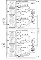
- an input signal Ix i,j such as Y, R, G or B field/frames of a video image sequence, are input to a set 10 of slow-edge filters and a set 20 of fast-edge filters.
- Each set 10, 20 of filters includes a horizontal bandpass/vertical lowpass filter 12, 22, a vertical bandpass/horizontal lowpass filter 14, 24, a first diagonal bandpass/orthogonal lowpass filter 16, 26 and a second diagonal bandpass/orthogonal lowpass filter 18, 28 which is orthogonal to the first diagonal filter.
- Preferred impulse-response kernel values and the associated spectrum magnitude, as 2D intensity graphs, for each filter 12-18, 22-28 in the two sets 10, 20 are shown adjacent the corresponding filter.
- the outputs from the filters 12-18, 22-28 are input to respective absolute blocks 31, 33, 35, 37, 41, 43, 45, 47.
- the resulting absolute values from the filters 12-18, 22-28 are input to respective summation circuits 32, 36, 42, 46 such that the absolute values from the horizontal bandpass filter 12 and vertical bandpass filter 14 of the slow-edge filter set 10 are summed, the absolute values for the diagonal bandpass filters 16, 18 of the slow-edge filter set are summed, the absolute values for the horizontal bandpass filter 22 and vertical bandpass filter 24 of the fast-edge filter set 20 are summed, and the absolute values for the diagonal bandpass filters 26, 28 of the fast-edge filter set are summed.
- IxSE i j
- IxFE i j
- the two filtered, weighted sum arrays from the output summation filters 39, 49 of the respective filter sets 10, 20 are each preferably cropped (52, 62) by two pixels on each boundary to remove 2D filtering edge effects on the boundaries.
- Each weighted sum array is then processed by common or typical 2D LPFs 54, 64 to mitigate aliasing during image size reduction, and then decimated (56, 66) in either the horizontal, vertical or both dimensions into reduced size 2D arrays, IxSEd[m,n] and IxFEd[m,n].
- a typical decimation value, D, for both horizontal and vertical decimation is sixteen, reducing the size of each array by a factor of 256.
- a decimation value of 32 may be preferred, reducing each array size by 1024. If both horizontal and vertical decimation factors are the same, then both of the ranges m and n are 1/D of the range of i and j.
- IxSEd[m,n] represents the localized slow-edge mapping
- IxFEd[m,n] represents the localized fast-edge mapping of the original image or field/frame. Since these two arrays are decimated to be much smaller than the original image or field/frame, they typically are small enough to allow software processing without the need for high speed software or hardware.
- the decimated arrays are then processed, preferably by a software application, to detect log-weighted localized maximum sharpness (LMS).
- LMS log-weighted localized maximum sharpness
- Delta[m,n] is the output of a difference block 70 into which the decimated arrays are input.
- the output from the difference block 70 is input to a maximum value block 72 and the fast edge decimated array is input to another maximum value block 74.
- the maximum values are then input to a divider 76 and multiplied (78) by a scale factor, SF, for setting the 0 dB or unity LMS value.
- the result is the LMS value which is then input to a logarithmic block 79 to produce the LMS output 80 as a dimensionless value in the range from 0 to infinite dB.
- This LogLMS calculation returns negative values and ranges from 0 ⁇ -> -inf dB, indicating increasing degradation in sharpness as a function of more negative values. To indicate increases in blur as increasingly larger positive values, the sign may simply be removed, making a localized blur metric the inverse (negative log) of the LMS.
- LogLMS provides a dimensionless value in dB
- the scaling of log(LMS) by a value other than 10 may be useful to create more meaningful numeric values for indicating sharpness or blur over a preferred range which have a better correlation to subjective assessment.
- max(IxFEd[m,n]) may be compared to a predetermined threshold so that, if it never exceeds that threshold, the image is determined to have so little detail as to preclude the need to compute a blur value. In this case the LMS value for that image may be flagged as invalid or ignored.
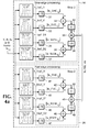
- a problem with detecting loss of sharpness on compressed video frames is that tiling or blockiness created by over-compression causes a loss in perceived detail, even though in fact it creates sharp horizontal and vertically aligned edges on DCT block boundaries. Also interlaced video frames of motion sequences may contain substantially horizontally aligned edges, sometimes called “jaggy or zipper effect", even though the image appears soft or blurred. To avoid this problem, LMS detection is performed only on diagonally aligned edges, as shown in Fig. 4 , setting the summed outputs of the horizontal and vertical filters to zero (82, 92).
- a sharpness map overlay, SMap[m,n] may be provided that indicates on each image or field/frame, with a valid computed LMS or LogLMS value, a localized region exceeding a preset sharpness threshold, Th, as shown in Fig. 5 .
- the max(delta[m,n,]) (72') is input to a multiplier 84 where it is multiplied by a constant 1-SR(%)/100 to produce a threshold value, Th.
- the threshold value is compared in a comparator 86 with delta[m,n,] and, if delta[m,n] is greater than the threshold, a switch 88 is switched to produce a "1" output, otherwise the switch produces a "0" output.
- the sharpness map is up-sized to the original image dimensions to overlay the image 100 with those blocks that have a non-zero value for SMap[m,n].
- This acts as a marker key 90 over a monochrome or luminance component of the image or field/frames to provide a colored or otherwise visible marker for those image areas that are above the threshold.
- This provides marking of the detected sharpest image regions by placing a colored marker 100 over the corresponding pixels of the monochrome image where the sharpness map values are non-zero.
- the resulting marked image or video frame sequence provides a realtime feedback to a user as to where in the image the LMS detection is seeing the sharpest edges and all edges that are SR percent less sharp.
- the ratio (106) of the maximum outputs (102, 104) from the localized, decimated fast-edge horizontal and vertical filters 66' to the localized, decimated fast-edge diagonal filters 66" is taken, as shown in Fig. 6 .
- the output from the decimated fast-edge diagonal filters 66" is multiplied (110) by a constant prior to having the maximum output (104) determined.
- the computed ratio, HV2Diag is typically near unity. However an excess of horizontal and vertical edges relative to the diagonal is detected when the ratio exceeds a predetermined tiling threshold level, TL, as determined by a comparator 108, setting a tiling flag, TF, to indicate the image may have excessive tiling.
- TL tiling threshold level
- a typical setting for TL is 1.1.
- the resulting tiling flag, TF may be used to indicate the over-compression case in order to turn off the horizontal and vertical filters by setting the weighting factor to zero (82, 92) to allow only diagonal processing, as discussed above with respect to Fig. 4 .
- LogLMS is compared (112), as shown in Fig. 7 , to a predetermined threshold, SD_Th, to determine if the image or frame sequence is consistently below this threshold. If LogLMS remains below this threshold for long durations as determined by a timer 114, such as several minutes, the program content is indicated or flagged via an UpConversionFlag as upconverted from a lower definition content.
- SD_Th a predetermined threshold for HD video in the formats of 1920x1080 and 1280x720 has been determined empirically to be -3.
- the output values may be presented to a software User Interface (Ul) that analyzes the luminance or RGB content of images, decompressed video files, decompressed streaming video over the internet, or uncompressed baseband video.
- Ul software User Interface
- the present invention provides a probe and method that filters an image or video frame sequence horizontally, vertically and diagonally using corresponding sets of fast-edge BPFs and slow-edge BPFs to calculate a weighted sum for each set, which sums are decimated and processed to determine a localized maximum sharpness (LMS) value in dB.
- LMS localized maximum sharpness
Landscapes
- Engineering & Computer Science (AREA)
- Multimedia (AREA)
- Signal Processing (AREA)
- Computer Vision & Pattern Recognition (AREA)
- Theoretical Computer Science (AREA)
- General Physics & Mathematics (AREA)
- Physics & Mathematics (AREA)
- General Health & Medical Sciences (AREA)
- Quality & Reliability (AREA)
- Health & Medical Sciences (AREA)
- Biomedical Technology (AREA)
- Image Processing (AREA)
- Studio Devices (AREA)
- Picture Signal Circuits (AREA)
Claims (15)
- Appareil sonde permettant de déterminer un flou d'image, comprenant :un premier ensemble de filtres de contours (20) destinés à détecter des contours rapides dans une image d'entrée de façon à produire une pluralité de sorties de filtres de contours rapides ;un second ensemble de filtres de contours (10) destinés à détecter des contours lents dans l'image d'entrée de façon à produire une pluralité de sorties de filtres de contours lents ;un moyen destiné à combiner les sorties de filtres de contours rapides pour produire une matrice de sorties de filtres de contours rapides ;un moyen destiné à combiner les sorties de filtres de contours lents pour produire une matrice de sorties de filtres de contours lents ;un moyen destiné à décimer individuellement les matrices de sorties de filtres de contours rapides et de contours lents pour produire une matrice décimée de filtres de contours rapides et une matrice décimée de filtres de contours lents ; etun moyen destiné à traiter les matrices décimées de filtres respectivement de contours rapides et de contours lents pour générer une valeur de netteté maximale localisée en tant que mesure du flou de l'image d'entrée ;dans lequel les contours rapides sont des contours nets et les contours lents sont des contours flous.
- Appareil sonde selon la revendication 1, dans lequel le premier ensemble (20) et le second ensemble (10) de filtres de contours comprennent chacun :un filtre de contours horizontal (12 ; 22) dont l'entrée est l'image d'entrée et produisant une sortie de filtre horizontal ;un filtre de contours vertical (14 ; 24) dont l'entrée est l'image d'entrée et produisant une sortie de filtre vertical ;un premier filtre de contours diagonal (16 ; 26) dont l'entrée est l'image d'entrée et produisant une sortie de filtre diagonal ; etun second filtre de contours diagonal (18 ; 28) orthogonal au premier filtre de contours diagonal dont l'entrée est l'image d'entrée et produisant une sortie de filtre diagonal.
- Appareil sonde selon la revendication 2, dans lequel chaque filtre de contours comprend un filtre ayant une caractéristique de bande passante dans une direction principale et une caractéristique de filtre passe-bas dans une direction orthogonale à la direction principale, les fréquences de bande passante du premier ensemble de filtres de contours (20) chevauchant les fréquences de bande passante du second ensemble de filtres de contours (10).
- Appareil sonde selon la revendication 2, dans lequel le moyen de combinaison de sorties de filtres de contours rapides et le moyen de combinaison de sorties de filtres de contours lents comprennent chacun :un premier bloc de calcul de somme (32 ; 42) destiné à combiner la sortie de filtre de contours horizontal et la sortie de filtre de contours vertical pour produire une première sortie de calcul de somme de filtres de contours ;un deuxième bloc de calcul de somme (36 ; 46) destiné à combiner la sortie de premier filtre de contours diagonal et la sortie de second filtre de contours diagonal pour produire une seconde sortie de calcul de somme de filtres de contours ;un moyen destiné à pondérer chacune des première et seconde sorties de calcul de somme de filtres de contours pour produire des sorties pondérées de somme de filtres de contours ; etun troisième bloc de calcul de somme (39 ; 49) destiné à combiner les sorties pondérées de somme de filtres de contours respectifs pour produire les matrices de filtres respectivement de contours rapides et de contours lents.
- Appareil sonde selon la revendication 1, dans lequel le moyen de décimation comprend :un filtre passe-bas (54 ; 64) pour chacune des matrices de filtres de contours rapides et de contours lents dont l'entrée est la matrice de filtres de contours respectifs de façon à produire des matrices filtrées de filtres de contours respectifs ; etun dispositif de décimation (56 ; 66) destiné à décimer chacune des matrices filtrées de filtres de contours pour produire les matrices décimées de filtres de contours respectifs.
- Appareil sonde selon la revendication 5, dans lequel le moyen de décimation comprend en outre un bloc de détourage (52 ; 62) destiné à détourer les contours des matrices de filtres respectivement de contours rapides et de contours lents avant l'entrée dans les filtres passe-bas respectifs (54 ; 64).
- Appareil sonde selon la revendication 1, dans lequel le moyen de traitement comprend :un moyen destiné à combiner les matrices décimées de filtres de contours rapides et de contours lents pour produire une matrice de filtres de différences ;un moyen destiné à générer un rapport entre la matrice de filtres de différences et la matrice décimée de filtres de contours rapides pour produire la valeur de netteté amenée à une valeur maximale localisée.
- Appareil sonde selon la revendication 7, dans lequel le moyen de génération de rapport comprend :un moyen destiné à obtenir les maximums (74 ; 72) de la matrice décimée de filtres de contours rapides et de la matrice de filtres de différences ;un moyen destiné à diviser (76) la matrice de filtres de différences de maximums par la matrice de filtres de contours rapides de maximums pour produire la valeur de netteté amenée à une valeur maximale localisée.
- Appareil sonde selon la revendication 8, dans lequel le moyen de génération de rapport comprend en outre un moyen destiné à multiplier (78) la sortie du moyen de division par un facteur de netteté pour produire la valeur de netteté amenée à une valeur maximale localisée ; et/ou
dans lequel le moyen de génération de rapport comprend en outre un moyen destiné à obtenir le log de la sortie (79) du moyen de multiplication pour produire la valeur de netteté amenée à une valeur maximale localisée en tant que valeur sans dimension. - Appareil sonde selon la revendication 1, dans lequel le moyen de traitement comprend :un bloc de différences (70) dont les matrices décimées de sorties de filtres de contours rapides et de contours lents sont les entrées de façon à produire une matrice de sorties de filtres de différences ;un moyen destiné à générer, à partir de la matrice de filtres de différences et du rapport de netteté, des marques localisées de superposition sur l'image d'entrée de façon à indiquer l'endroit où apparaissent les contours les plus nets dans l'image d'entrée.
- Appareil sonde selon la revendication 10, dans lequel le moyen de génération comprend :un générateur de seuil dont les entrées sont la matrice de sorties de filtres de différences et le rapport de netteté et produisant une valeur de seuil en tant que sortie ;un comparateur (86) dont les entrées sont la matrice de sorties de filtres de différences et la valeur de seuil et produisant des marques localisées en tant que sortie lorsque la matrice de sorties de filtres de différences dépasse la valeur de seuil.
- Appareil sonde selon la revendication 10, comprenant en outre un moyen permettant d'invalider les sorties de filtres de contours horizontal et vertical de chacun des premier et second ensembles de filtres de contours (20 ; 10) en réponse à l'indicateur de pavage, de sorte que les sorties de filtres de contours des premier et second ensembles de filtres de contours (20 ; 10) ne reflètent que les sorties de filtres des paires de filtres de contours diagonaux respectifs.
- Procédé selon la revendication 1, comprenant en outre :un bloc de comparaison (112) destiné à comparer la valeur de netteté maximale localisée avec un seuil de netteté ; etun moyen destiné à générer un indicateur de mise à l'échelle supérieure lorsque le seuil de netteté est inférieur à la valeur de netteté maximale localisée pendant une durée prédéfinie, indiquant que l'image a fait l'objet d'une mise à l'échelle supérieure à partir d'une image de résolution plus faible.
- Procédé de détermination de flou d'image consistant à :filtrer une image d'entrée au moyen d'un premier ensemble de filtres de contours (20) destinés à détecter des contours rapides dans l'image d'entrée de façon à produire une pluralité de sorties de filtres de contours rapides ;filtrer l'image d'entrée au moyen d'un second ensemble de filtres de contours (10) destinés à détecter des contours lents dans l'image d'entrée de façon à produire une pluralité de sorties de filtres de contours lents ;combiner les sorties de filtres de contours rapides pour produire une matrice de sorties de filtres de contours rapides ;combiner les sorties de filtres de contours lents pour produire une matrice de sorties de filtres de contours lents ;décimer individuellement les matrices de sorties de filtres de contours rapides et de contours lents pour produire une matrice décimée de filtres de contours rapides et une matrice décimée de filtres de contours lents ; ettraiter les matrices décimées de filtres respectivement de contours rapides et de contours lents pour générer une valeur de netteté maximale localisée en tant que mesure du flou de l'image d'entrée ;dans lequel les contours rapides sont des contours nets et les contours lents sont des contours flous.
- Procédé selon la revendication 14, comprenant en outre les étapes consistant à :combiner les sorties de filtres de contours horizontal et vertical du premier ensemble de filtres de contours pour produire une première matrice de sorties de filtres de contours rapides ;combiner les sorties de premier et second filtres de contours diagonaux du premier ensemble de filtres de contours pour produire une seconde matrice de sorties de filtres de contours rapides ;décimer les première et seconde matrices de sorties de filtres de contours rapides pour produire des première et seconde matrices décimées de sorties de filtres de contours rapides ; etcomparer un rapport des premiers et seconds filtres de contours rapides avec un seuil de pavage pour produire un indicateur de pavage indicatif d'artefacts de blocs dans l'image d'entrée.
Applications Claiming Priority (1)
| Application Number | Priority Date | Filing Date | Title |
|---|---|---|---|
| US12/976,729 US8754988B2 (en) | 2010-12-22 | 2010-12-22 | Blur detection with local sharpness map |
Publications (3)
| Publication Number | Publication Date |
|---|---|
| EP2469837A2 EP2469837A2 (fr) | 2012-06-27 |
| EP2469837A3 EP2469837A3 (fr) | 2013-08-21 |
| EP2469837B1 true EP2469837B1 (fr) | 2016-09-07 |
Family
ID=45349016
Family Applications (1)
| Application Number | Title | Priority Date | Filing Date |
|---|---|---|---|
| EP11189901.9A Active EP2469837B1 (fr) | 2010-12-22 | 2011-11-21 | Détection de flou avec carte à netteté locale |
Country Status (4)
| Country | Link |
|---|---|
| US (1) | US8754988B2 (fr) |
| EP (1) | EP2469837B1 (fr) |
| JP (1) | JP5979856B2 (fr) |
| CN (1) | CN102665088B (fr) |
Families Citing this family (30)
| Publication number | Priority date | Publication date | Assignee | Title |
|---|---|---|---|---|
| US9769354B2 (en) | 2005-03-24 | 2017-09-19 | Kofax, Inc. | Systems and methods of processing scanned data |
| US9137417B2 (en) | 2005-03-24 | 2015-09-15 | Kofax, Inc. | Systems and methods for processing video data |
| US9349046B2 (en) | 2009-02-10 | 2016-05-24 | Kofax, Inc. | Smart optical input/output (I/O) extension for context-dependent workflows |
| US9576272B2 (en) | 2009-02-10 | 2017-02-21 | Kofax, Inc. | Systems, methods and computer program products for determining document validity |
| US8958605B2 (en) | 2009-02-10 | 2015-02-17 | Kofax, Inc. | Systems, methods and computer program products for determining document validity |
| US9767354B2 (en) | 2009-02-10 | 2017-09-19 | Kofax, Inc. | Global geographic information retrieval, validation, and normalization |
| US8774516B2 (en) | 2009-02-10 | 2014-07-08 | Kofax, Inc. | Systems, methods and computer program products for determining document validity |
| US8879846B2 (en) | 2009-02-10 | 2014-11-04 | Kofax, Inc. | Systems, methods and computer program products for processing financial documents |
| US9058515B1 (en) | 2012-01-12 | 2015-06-16 | Kofax, Inc. | Systems and methods for identification document processing and business workflow integration |
| US9165187B2 (en) | 2012-01-12 | 2015-10-20 | Kofax, Inc. | Systems and methods for mobile image capture and processing |
| US9483794B2 (en) | 2012-01-12 | 2016-11-01 | Kofax, Inc. | Systems and methods for identification document processing and business workflow integration |
| US10146795B2 (en) | 2012-01-12 | 2018-12-04 | Kofax, Inc. | Systems and methods for mobile image capture and processing |
| US9058580B1 (en) | 2012-01-12 | 2015-06-16 | Kofax, Inc. | Systems and methods for identification document processing and business workflow integration |
| US10860931B1 (en) * | 2012-12-31 | 2020-12-08 | DataInfoCom USA, Inc. | Method and system for performing analysis using unstructured data |
| US9208536B2 (en) | 2013-09-27 | 2015-12-08 | Kofax, Inc. | Systems and methods for three dimensional geometric reconstruction of captured image data |
| US9355312B2 (en) | 2013-03-13 | 2016-05-31 | Kofax, Inc. | Systems and methods for classifying objects in digital images captured using mobile devices |
| WO2014160426A1 (fr) | 2013-03-13 | 2014-10-02 | Kofax, Inc. | Classification des objets dans des images numériques capturées à l'aide de dispositifs mobiles |
| CN104112266B (zh) * | 2013-04-19 | 2017-03-22 | 浙江大华技术股份有限公司 | 一种图像边缘虚化的检测方法和装置 |
| US20140316841A1 (en) | 2013-04-23 | 2014-10-23 | Kofax, Inc. | Location-based workflows and services |
| WO2014179752A1 (fr) | 2013-05-03 | 2014-11-06 | Kofax, Inc. | Systèmes et procédés pour détecter et classifier des objets dans une vidéo capturée à l'aide de dispositifs mobiles |
| US9237257B1 (en) * | 2013-06-14 | 2016-01-12 | Xilinx, Inc. | Circuits for and methods of generating a digital image |
| WO2015073920A1 (fr) | 2013-11-15 | 2015-05-21 | Kofax, Inc. | Systèmes et procédés de génération d'images composites de longs documents en utilisant des données vidéo mobiles |
| US9760788B2 (en) | 2014-10-30 | 2017-09-12 | Kofax, Inc. | Mobile document detection and orientation based on reference object characteristics |
| US10242285B2 (en) | 2015-07-20 | 2019-03-26 | Kofax, Inc. | Iterative recognition-guided thresholding and data extraction |
| CN105069783B (zh) * | 2015-07-23 | 2019-03-01 | 北京金山安全软件有限公司 | 一种模糊图片识别方法及装置 |
| CN105611284B (zh) * | 2015-12-23 | 2017-10-10 | 小米科技有限责任公司 | 图像清晰度判定方法、装置及系统 |
| US9779296B1 (en) | 2016-04-01 | 2017-10-03 | Kofax, Inc. | Content-based detection and three dimensional geometric reconstruction of objects in image and video data |
| US10803350B2 (en) | 2017-11-30 | 2020-10-13 | Kofax, Inc. | Object detection and image cropping using a multi-detector approach |
| US11120536B2 (en) | 2018-12-12 | 2021-09-14 | Samsung Electronics Co., Ltd | Apparatus and method for determining image sharpness |
| CN118552515B (zh) * | 2024-06-19 | 2026-02-06 | 浙江大学 | 一种基于dft矩阵整数近似分解的紫外图像模糊检测方法 |
Family Cites Families (13)
| Publication number | Priority date | Publication date | Assignee | Title |
|---|---|---|---|---|
| JP2589298B2 (ja) * | 1987-01-28 | 1997-03-12 | キヤノン株式会社 | 符号化画像データの復号化装置 |
| US5999189A (en) * | 1995-08-04 | 1999-12-07 | Microsoft Corporation | Image compression to reduce pixel and texture memory requirements in a real-time image generator |
| JP3657145B2 (ja) * | 1999-05-17 | 2005-06-08 | シャープ株式会社 | 輪郭補正装置 |
| WO2007118097A1 (fr) * | 2006-04-03 | 2007-10-18 | Omnivision Cdm Optics, Inc. | systèmes et méthodes d'imagerie optique utilisant UN traitement d'image non linéaire et/ou spatialement variable |
| AU2003225228A1 (en) * | 2002-05-03 | 2003-11-17 | Donnelly Corporation | Object detection system for vehicle |
| GB0224357D0 (en) | 2002-10-19 | 2002-11-27 | Eastman Kodak Co | Image processing |
| WO2004044843A2 (fr) * | 2002-11-06 | 2004-05-27 | Digivision, Inc. | Systemes et procedes d'amelioration d'images en plusieurs dimensions |
| EP1642233A2 (fr) | 2003-06-27 | 2006-04-05 | Koninklijke Philips Electronics N.V. | Procede de mesure de nettete pour des images et de la video ameliorees par voie asymetrique |
| JP4160887B2 (ja) * | 2003-09-18 | 2008-10-08 | 株式会社リコー | 画像処理装置および画像処理方法 |
| KR100553892B1 (ko) * | 2003-10-13 | 2006-02-24 | 삼성전자주식회사 | 디지털 영상 보간 방법 및 장치 |
| WO2005101312A2 (fr) * | 2004-04-13 | 2005-10-27 | Aic | Procede skr fractal destine a l'evaluation de la qualite d'images |
| TWI311679B (en) * | 2006-04-28 | 2009-07-01 | Primax Electronics Ltd | A method of evaluating minimum sampling steps of auto focus |
| US8503814B2 (en) * | 2009-01-19 | 2013-08-06 | Csr Technology Inc. | Method and apparatus for spectrum estimation |
-
2010
- 2010-12-22 US US12/976,729 patent/US8754988B2/en active Active
-
2011
- 2011-11-21 EP EP11189901.9A patent/EP2469837B1/fr active Active
- 2011-12-07 JP JP2011267867A patent/JP5979856B2/ja active Active
- 2011-12-22 CN CN201110434946.5A patent/CN102665088B/zh active Active
Also Published As
| Publication number | Publication date |
|---|---|
| JP5979856B2 (ja) | 2016-08-31 |
| EP2469837A2 (fr) | 2012-06-27 |
| EP2469837A3 (fr) | 2013-08-21 |
| JP2012134964A (ja) | 2012-07-12 |
| CN102665088A (zh) | 2012-09-12 |
| US20120162527A1 (en) | 2012-06-28 |
| CN102665088B (zh) | 2016-03-09 |
| US8754988B2 (en) | 2014-06-17 |
Similar Documents
| Publication | Publication Date | Title |
|---|---|---|
| EP2469837B1 (fr) | Détection de flou avec carte à netteté locale | |
| KR101108435B1 (ko) | 의사윤곽 제거 방법 및 이 방법이 적용되는 디스플레이장치 | |
| EP1480449B1 (fr) | Noyautage adaptable pour l'accentuation d'un signal vidéo | |
| KR101112139B1 (ko) | 부호화된 영상의 확대비 및 노이즈 강도 추정장치 및 방법 | |
| US8805114B2 (en) | Content adaptive edge and detail enhancement for image and video processing | |
| JP5107342B2 (ja) | 精度平滑特性を増大させる画像改善 | |
| Ferzli et al. | A no-reference objective image sharpness metric based on just-noticeable blur and probability summation | |
| EP1865726A1 (fr) | Procédé et appareil pour mesurer l'intensité du bruit MPEG d'une image numérique compressée | |
| EP1383344A2 (fr) | Mesure du flou de séquences d'images | |
| JPH11250246A (ja) | 画像処理方法および装置 | |
| US20040131117A1 (en) | Method and apparatus for improving MPEG picture compression | |
| KR20100047885A (ko) | 디지털 객체 처리방법 및 관련 시스템 | |
| US8064718B2 (en) | Filter for adaptive noise reduction and sharpness enhancement for electronically displayed pictures | |
| KR20160104960A (ko) | 크로스 커널 구조의 중간값 필터를 이용한 영상 잡음 제거장치 및 방법 | |
| Vu et al. | S3: A spectral and spatial sharpness measure | |
| Rabie | Adaptive hybrid mean and median filtering of high-ISO long-exposure sensor noise for digital photography | |
| EP1512121B1 (fr) | Unite et procede de calcul d'une bordure vive | |
| US20060232709A1 (en) | Interframe noise reduction for video | |
| JP4663349B2 (ja) | スクリーン周波数を推定する方法及び装置 | |
| EP1289318A1 (fr) | Procédé et système pour mesurer la distorsion perceptive d' images | |
| Ryu et al. | No-reference sharpness metric based on inherent sharpness | |
| JP2005277503A (ja) | 画像処理方法および装置並びにプログラム | |
| Sadaka et al. | Efficient perceptual attentive super-resolution | |
| Lee | Edge statistics-based image scale ratio and noise strength estimation in DCT-coded images | |
| JPH10243238A (ja) | ディジタル画像のノイズ抑制およびシャープネス強調のための画像処理方法 |
Legal Events
| Date | Code | Title | Description |
|---|---|---|---|
| AK | Designated contracting states |
Kind code of ref document: A2 Designated state(s): AL AT BE BG CH CY CZ DE DK EE ES FI FR GB GR HR HU IE IS IT LI LT LU LV MC MK MT NL NO PL PT RO RS SE SI SK SM TR |
|
| AX | Request for extension of the european patent |
Extension state: BA ME |
|
| PUAI | Public reference made under article 153(3) epc to a published international application that has entered the european phase |
Free format text: ORIGINAL CODE: 0009012 |
|
| PUAL | Search report despatched |
Free format text: ORIGINAL CODE: 0009013 |
|
| AK | Designated contracting states |
Kind code of ref document: A3 Designated state(s): AL AT BE BG CH CY CZ DE DK EE ES FI FR GB GR HR HU IE IS IT LI LT LU LV MC MK MT NL NO PL PT RO RS SE SI SK SM TR |
|
| AX | Request for extension of the european patent |
Extension state: BA ME |
|
| RIC1 | Information provided on ipc code assigned before grant |
Ipc: G06T 5/00 20060101ALI20130718BHEP Ipc: H04N 17/00 20060101ALI20130718BHEP Ipc: H04N 5/14 20060101AFI20130718BHEP |
|
| 17P | Request for examination filed |
Effective date: 20140221 |
|
| RBV | Designated contracting states (corrected) |
Designated state(s): AL AT BE BG CH CY CZ DE DK EE ES FI FR GB GR HR HU IE IS IT LI LT LU LV MC MK MT NL NO PL PT RO RS SE SI SK SM TR |
|
| RAP1 | Party data changed (applicant data changed or rights of an application transferred) |
Owner name: TEKTRONIX, INC. |
|
| REG | Reference to a national code |
Ref country code: DE Ref legal event code: R079 Ref document number: 602011030055 Country of ref document: DE Free format text: PREVIOUS MAIN CLASS: H04N0005140000 Ipc: G06T0007000000 |
|
| GRAP | Despatch of communication of intention to grant a patent |
Free format text: ORIGINAL CODE: EPIDOSNIGR1 |
|
| RIC1 | Information provided on ipc code assigned before grant |
Ipc: H04N 5/21 20060101ALI20160404BHEP Ipc: H04N 5/14 20060101ALI20160404BHEP Ipc: G06T 7/00 20060101AFI20160404BHEP Ipc: H04N 17/00 20060101ALI20160404BHEP |
|
| INTG | Intention to grant announced |
Effective date: 20160511 |
|
| GRAS | Grant fee paid |
Free format text: ORIGINAL CODE: EPIDOSNIGR3 |
|
| GRAA | (expected) grant |
Free format text: ORIGINAL CODE: 0009210 |
|
| AK | Designated contracting states |
Kind code of ref document: B1 Designated state(s): AL AT BE BG CH CY CZ DE DK EE ES FI FR GB GR HR HU IE IS IT LI LT LU LV MC MK MT NL NO PL PT RO RS SE SI SK SM TR |
|
| REG | Reference to a national code |
Ref country code: GB Ref legal event code: FG4D |
|
| REG | Reference to a national code |
Ref country code: CH Ref legal event code: EP |
|
| REG | Reference to a national code |
Ref country code: IE Ref legal event code: FG4D |
|
| REG | Reference to a national code |
Ref country code: AT Ref legal event code: REF Ref document number: 827455 Country of ref document: AT Kind code of ref document: T Effective date: 20161015 |
|
| REG | Reference to a national code |
Ref country code: DE Ref legal event code: R096 Ref document number: 602011030055 Country of ref document: DE |
|
| REG | Reference to a national code |
Ref country code: FR Ref legal event code: PLFP Year of fee payment: 6 |
|
| REG | Reference to a national code |
Ref country code: LT Ref legal event code: MG4D |
|
| REG | Reference to a national code |
Ref country code: NL Ref legal event code: MP Effective date: 20160907 |
|
| PG25 | Lapsed in a contracting state [announced via postgrant information from national office to epo] |
Ref country code: HR Free format text: LAPSE BECAUSE OF FAILURE TO SUBMIT A TRANSLATION OF THE DESCRIPTION OR TO PAY THE FEE WITHIN THE PRESCRIBED TIME-LIMIT Effective date: 20160907 Ref country code: NO Free format text: LAPSE BECAUSE OF FAILURE TO SUBMIT A TRANSLATION OF THE DESCRIPTION OR TO PAY THE FEE WITHIN THE PRESCRIBED TIME-LIMIT Effective date: 20161207 Ref country code: LT Free format text: LAPSE BECAUSE OF FAILURE TO SUBMIT A TRANSLATION OF THE DESCRIPTION OR TO PAY THE FEE WITHIN THE PRESCRIBED TIME-LIMIT Effective date: 20160907 Ref country code: FI Free format text: LAPSE BECAUSE OF FAILURE TO SUBMIT A TRANSLATION OF THE DESCRIPTION OR TO PAY THE FEE WITHIN THE PRESCRIBED TIME-LIMIT Effective date: 20160907 Ref country code: RS Free format text: LAPSE BECAUSE OF FAILURE TO SUBMIT A TRANSLATION OF THE DESCRIPTION OR TO PAY THE FEE WITHIN THE PRESCRIBED TIME-LIMIT Effective date: 20160907 |
|
| REG | Reference to a national code |
Ref country code: AT Ref legal event code: MK05 Ref document number: 827455 Country of ref document: AT Kind code of ref document: T Effective date: 20160907 |
|
| PG25 | Lapsed in a contracting state [announced via postgrant information from national office to epo] |
Ref country code: ES Free format text: LAPSE BECAUSE OF FAILURE TO SUBMIT A TRANSLATION OF THE DESCRIPTION OR TO PAY THE FEE WITHIN THE PRESCRIBED TIME-LIMIT Effective date: 20160907 Ref country code: BE Free format text: LAPSE BECAUSE OF NON-PAYMENT OF DUE FEES Effective date: 20161130 Ref country code: LV Free format text: LAPSE BECAUSE OF FAILURE TO SUBMIT A TRANSLATION OF THE DESCRIPTION OR TO PAY THE FEE WITHIN THE PRESCRIBED TIME-LIMIT Effective date: 20160907 Ref country code: GR Free format text: LAPSE BECAUSE OF FAILURE TO SUBMIT A TRANSLATION OF THE DESCRIPTION OR TO PAY THE FEE WITHIN THE PRESCRIBED TIME-LIMIT Effective date: 20161208 Ref country code: NL Free format text: LAPSE BECAUSE OF FAILURE TO SUBMIT A TRANSLATION OF THE DESCRIPTION OR TO PAY THE FEE WITHIN THE PRESCRIBED TIME-LIMIT Effective date: 20160907 Ref country code: SE Free format text: LAPSE BECAUSE OF FAILURE TO SUBMIT A TRANSLATION OF THE DESCRIPTION OR TO PAY THE FEE WITHIN THE PRESCRIBED TIME-LIMIT Effective date: 20160907 |
|
| PG25 | Lapsed in a contracting state [announced via postgrant information from national office to epo] |
Ref country code: EE Free format text: LAPSE BECAUSE OF FAILURE TO SUBMIT A TRANSLATION OF THE DESCRIPTION OR TO PAY THE FEE WITHIN THE PRESCRIBED TIME-LIMIT Effective date: 20160907 Ref country code: RO Free format text: LAPSE BECAUSE OF FAILURE TO SUBMIT A TRANSLATION OF THE DESCRIPTION OR TO PAY THE FEE WITHIN THE PRESCRIBED TIME-LIMIT Effective date: 20160907 |
|
| PG25 | Lapsed in a contracting state [announced via postgrant information from national office to epo] |
Ref country code: SM Free format text: LAPSE BECAUSE OF FAILURE TO SUBMIT A TRANSLATION OF THE DESCRIPTION OR TO PAY THE FEE WITHIN THE PRESCRIBED TIME-LIMIT Effective date: 20160907 Ref country code: IS Free format text: LAPSE BECAUSE OF FAILURE TO SUBMIT A TRANSLATION OF THE DESCRIPTION OR TO PAY THE FEE WITHIN THE PRESCRIBED TIME-LIMIT Effective date: 20170107 Ref country code: BE Free format text: LAPSE BECAUSE OF FAILURE TO SUBMIT A TRANSLATION OF THE DESCRIPTION OR TO PAY THE FEE WITHIN THE PRESCRIBED TIME-LIMIT Effective date: 20160907 Ref country code: AT Free format text: LAPSE BECAUSE OF FAILURE TO SUBMIT A TRANSLATION OF THE DESCRIPTION OR TO PAY THE FEE WITHIN THE PRESCRIBED TIME-LIMIT Effective date: 20160907 Ref country code: PT Free format text: LAPSE BECAUSE OF FAILURE TO SUBMIT A TRANSLATION OF THE DESCRIPTION OR TO PAY THE FEE WITHIN THE PRESCRIBED TIME-LIMIT Effective date: 20170109 Ref country code: SK Free format text: LAPSE BECAUSE OF FAILURE TO SUBMIT A TRANSLATION OF THE DESCRIPTION OR TO PAY THE FEE WITHIN THE PRESCRIBED TIME-LIMIT Effective date: 20160907 Ref country code: PL Free format text: LAPSE BECAUSE OF FAILURE TO SUBMIT A TRANSLATION OF THE DESCRIPTION OR TO PAY THE FEE WITHIN THE PRESCRIBED TIME-LIMIT Effective date: 20160907 Ref country code: BG Free format text: LAPSE BECAUSE OF FAILURE TO SUBMIT A TRANSLATION OF THE DESCRIPTION OR TO PAY THE FEE WITHIN THE PRESCRIBED TIME-LIMIT Effective date: 20161207 Ref country code: CZ Free format text: LAPSE BECAUSE OF FAILURE TO SUBMIT A TRANSLATION OF THE DESCRIPTION OR TO PAY THE FEE WITHIN THE PRESCRIBED TIME-LIMIT Effective date: 20160907 |
|
| REG | Reference to a national code |
Ref country code: DE Ref legal event code: R097 Ref document number: 602011030055 Country of ref document: DE |
|
| REG | Reference to a national code |
Ref country code: CH Ref legal event code: PL |
|
| PLBE | No opposition filed within time limit |
Free format text: ORIGINAL CODE: 0009261 |
|
| STAA | Information on the status of an ep patent application or granted ep patent |
Free format text: STATUS: NO OPPOSITION FILED WITHIN TIME LIMIT |
|
| PG25 | Lapsed in a contracting state [announced via postgrant information from national office to epo] |
Ref country code: LI Free format text: LAPSE BECAUSE OF NON-PAYMENT OF DUE FEES Effective date: 20161130 Ref country code: CH Free format text: LAPSE BECAUSE OF NON-PAYMENT OF DUE FEES Effective date: 20161130 Ref country code: DK Free format text: LAPSE BECAUSE OF FAILURE TO SUBMIT A TRANSLATION OF THE DESCRIPTION OR TO PAY THE FEE WITHIN THE PRESCRIBED TIME-LIMIT Effective date: 20160907 |
|
| 26N | No opposition filed |
Effective date: 20170608 |
|
| REG | Reference to a national code |
Ref country code: IE Ref legal event code: MM4A |
|
| PG25 | Lapsed in a contracting state [announced via postgrant information from national office to epo] |
Ref country code: SI Free format text: LAPSE BECAUSE OF FAILURE TO SUBMIT A TRANSLATION OF THE DESCRIPTION OR TO PAY THE FEE WITHIN THE PRESCRIBED TIME-LIMIT Effective date: 20160907 |
|
| PG25 | Lapsed in a contracting state [announced via postgrant information from national office to epo] |
Ref country code: LU Free format text: LAPSE BECAUSE OF NON-PAYMENT OF DUE FEES Effective date: 20161130 |
|
| REG | Reference to a national code |
Ref country code: FR Ref legal event code: PLFP Year of fee payment: 7 |
|
| PG25 | Lapsed in a contracting state [announced via postgrant information from national office to epo] |
Ref country code: IE Free format text: LAPSE BECAUSE OF NON-PAYMENT OF DUE FEES Effective date: 20161121 |
|
| PGFP | Annual fee paid to national office [announced via postgrant information from national office to epo] |
Ref country code: FR Payment date: 20171127 Year of fee payment: 7 |
|
| PGFP | Annual fee paid to national office [announced via postgrant information from national office to epo] |
Ref country code: IT Payment date: 20171123 Year of fee payment: 7 |
|
| PG25 | Lapsed in a contracting state [announced via postgrant information from national office to epo] |
Ref country code: HU Free format text: LAPSE BECAUSE OF FAILURE TO SUBMIT A TRANSLATION OF THE DESCRIPTION OR TO PAY THE FEE WITHIN THE PRESCRIBED TIME-LIMIT; INVALID AB INITIO Effective date: 20111121 Ref country code: CY Free format text: LAPSE BECAUSE OF FAILURE TO SUBMIT A TRANSLATION OF THE DESCRIPTION OR TO PAY THE FEE WITHIN THE PRESCRIBED TIME-LIMIT Effective date: 20160907 |
|
| PG25 | Lapsed in a contracting state [announced via postgrant information from national office to epo] |
Ref country code: TR Free format text: LAPSE BECAUSE OF FAILURE TO SUBMIT A TRANSLATION OF THE DESCRIPTION OR TO PAY THE FEE WITHIN THE PRESCRIBED TIME-LIMIT Effective date: 20160907 Ref country code: MC Free format text: LAPSE BECAUSE OF FAILURE TO SUBMIT A TRANSLATION OF THE DESCRIPTION OR TO PAY THE FEE WITHIN THE PRESCRIBED TIME-LIMIT Effective date: 20160907 Ref country code: MK Free format text: LAPSE BECAUSE OF FAILURE TO SUBMIT A TRANSLATION OF THE DESCRIPTION OR TO PAY THE FEE WITHIN THE PRESCRIBED TIME-LIMIT Effective date: 20160907 |
|
| PG25 | Lapsed in a contracting state [announced via postgrant information from national office to epo] |
Ref country code: MT Free format text: LAPSE BECAUSE OF NON-PAYMENT OF DUE FEES Effective date: 20161121 |
|
| PG25 | Lapsed in a contracting state [announced via postgrant information from national office to epo] |
Ref country code: AL Free format text: LAPSE BECAUSE OF FAILURE TO SUBMIT A TRANSLATION OF THE DESCRIPTION OR TO PAY THE FEE WITHIN THE PRESCRIBED TIME-LIMIT Effective date: 20160907 |
|
| PG25 | Lapsed in a contracting state [announced via postgrant information from national office to epo] |
Ref country code: FR Free format text: LAPSE BECAUSE OF NON-PAYMENT OF DUE FEES Effective date: 20181130 Ref country code: IT Free format text: LAPSE BECAUSE OF NON-PAYMENT OF DUE FEES Effective date: 20181121 |
|
| REG | Reference to a national code |
Ref country code: GB Ref legal event code: 732E Free format text: REGISTERED BETWEEN 20210211 AND 20210217 |
|
| REG | Reference to a national code |
Ref country code: DE Ref legal event code: R082 Ref document number: 602011030055 Country of ref document: DE Representative=s name: HGF EUROPE LLP, DE Ref country code: DE Ref legal event code: R081 Ref document number: 602011030055 Country of ref document: DE Owner name: PROJECT GIANTS, LLC, NEVADA CITY, US Free format text: FORMER OWNER: TEKTRONIX, INC., BEAVERTON, OREG., US |
|
| PGFP | Annual fee paid to national office [announced via postgrant information from national office to epo] |
Ref country code: DE Payment date: 20251128 Year of fee payment: 15 |
|
| PGFP | Annual fee paid to national office [announced via postgrant information from national office to epo] |
Ref country code: GB Payment date: 20251127 Year of fee payment: 15 |