EP2469876B1 - Vorrichtung zur Steuerung einer stereoskopischen Bildanzeige und Betriebssteuerverfahren dafür - Google Patents
Vorrichtung zur Steuerung einer stereoskopischen Bildanzeige und Betriebssteuerverfahren dafür Download PDFInfo
- Publication number
- EP2469876B1 EP2469876B1 EP11795481.8A EP11795481A EP2469876B1 EP 2469876 B1 EP2469876 B1 EP 2469876B1 EP 11795481 A EP11795481 A EP 11795481A EP 2469876 B1 EP2469876 B1 EP 2469876B1
- Authority
- EP
- European Patent Office
- Prior art keywords
- stereoscopic
- stereoscopic image
- image
- blurring
- parallax
- Prior art date
- Legal status (The legal status is an assumption and is not a legal conclusion. Google has not performed a legal analysis and makes no representation as to the accuracy of the status listed.)
- Not-in-force
Links
Images


Classifications
-
- H—ELECTRICITY
- H04—ELECTRIC COMMUNICATION TECHNIQUE
- H04N—PICTORIAL COMMUNICATION, e.g. TELEVISION
- H04N13/00—Stereoscopic video systems; Multi-view video systems; Details thereof
- H04N13/10—Processing, recording or transmission of stereoscopic or multi-view image signals
- H04N13/106—Processing image signals
- H04N13/172—Processing image signals image signals comprising non-image signal components, e.g. headers or format information
- H04N13/178—Metadata, e.g. disparity information
-
- H—ELECTRICITY
- H04—ELECTRIC COMMUNICATION TECHNIQUE
- H04N—PICTORIAL COMMUNICATION, e.g. TELEVISION
- H04N13/00—Stereoscopic video systems; Multi-view video systems; Details thereof
- H04N13/10—Processing, recording or transmission of stereoscopic or multi-view image signals
- H04N13/106—Processing image signals
- H04N13/122—Improving the three-dimensional [3D] impression of stereoscopic images by modifying image signal contents, e.g. by filtering or adding monoscopic depth cues
-
- H—ELECTRICITY
- H04—ELECTRIC COMMUNICATION TECHNIQUE
- H04N—PICTORIAL COMMUNICATION, e.g. TELEVISION
- H04N2213/00—Details of stereoscopic systems
- H04N2213/002—Eyestrain reduction by processing stereoscopic signals or controlling stereoscopic devices
Definitions
- This invention relates to a stereoscopic image display control apparatus and to a method of controlling the operation of this apparatus.
- WO-A1-2009/149413 discloses a method and apparatus for selectively blurring parts of an image set according to differences in disparity between successive images.
- the method may involve detecting regions of disparity between adjacent views, and then blurring those regions by weighted local pixel averaging.
- the relationship between the blur radius and the disparity is preferentially non-linear to maintain sharpness of low disparity regions.
- US-A1-2007/0236560 discloses three general designs for reducing parallax in a moving picture.
- One design comprises stretching graphics content near the left and right frame edges of stereo pair elements in order to modify parallax settings.
- a second design comprises identifying a plurality of substantially corresponding points in a left eye view and right eye view and bringing the plurality of substantially corresponding points closer together using a morph technique.
- the third design entails fading a portion of a right eye view with a portion of a left eye view near or proximate an edge of the image.
- WO-A1-2004/084550 discloses a stereoscopic video photographing/displaying system comprising a stereoscopic video imaging unit having two imaging means and outputting video information therefrom, a stereoscopic video display for displaying different videos on both eyes of a viewer, and a medium for transmitting image information from the stereoscopic video imaging unit to the stereoscopic video display, the stereoscopic video imaging unit comprising means for measuring cross point information concerning the cross point (CP) of the optical axes of the imaging means, characterized in that an offset setting means for delivering information including the CP information and the video information to the medium and displaying the different videos while shifting based on the video information, the cross point information, and the size information of an image being displayed by the stereoscopic video display.
- CP cross point
- EP-A2-2106150 discloses a method, apparatus and program for stereoscopic videos. Fatigue in users who stereoscopically view stereoscopic videos is reduced during switching among scenes in stereoscopic videos.
- a video input section receives input of stereoscopic videos constituted by a plurality of frames, which are viewable stereoscopically.
- a scene detecting section detects positions within the stereoscopic videos at which scene changes occur.
- a perceived depth adjusting section administers perceived depth adjusting processes that adjust the perceived depths of the stereoscopic videos such that the perceived depth changes gradually at the positions at which scene changes occur, to obtain processed stereoscopic videos.
- WO-A1-2010/046824 discloses a system and method of processing an input three dimensional video signal comprising multiple views, the method comprising: determining a far disparity estimate indicative of the largest disparity value for the input three dimensional video signal, a near disparity estimate indicative of the smallest disparity value for a spatial region within the input three dimensional video signal, adapting the input three dimensional video signal by shifting the input three dimensional video signal backwards by means of a disparity shift based on the far disparity estimate and generating an overlay within the spatial region for the shifted three dimensional video signal based on the near disparity estimate and the disparity shift.
- An object of the present invention is to display a stereoscopic image that is devoid of viewing discomfort.
- the present invention provides a stereoscopic image display control apparatus according to Claim 1.
- the present invention also provides a method of controlling operation of a stereoscopic image display control apparatus according to Claim 5.
- stereoscopic image data and cross-point information have been recorded on a recording medium.
- the stereoscopic image data and cross-point information are read from the recording medium and an image portion in the stereoscopic image representing a subject at a position deeper than the cross point, which is represented by the cross-point information, is caused to blur in such a manner that the deeper into the stereoscopic image from the cross point, the more the amount of blurring applied.
- the stereoscopic image thus blurred is displayed. If an image portion representing a subject shallower that the cross point is caused to blur, there are instances where the resulting image cannot be enjoyed as a stereoscopic image. However, an image portion representing a subject shallower that the cross point is not caused to blur.
- the first blurring unit blurs an image portion, which represents a subject at a position deeper than the cross point detected by the cross point detection unit in the stereoscopic image, in such a manner that the larger a display screen of the display device, the more the amount of blurring becomes.
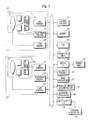
- Fig. 1 is a block diagram illustrating the electrical configuration of a stereoscopic moving-image imaging digital camera.
- the operation of the stereoscopic moving-image imaging digital camera is controlled by a central control unit 31.
- the stereoscopic moving-image imaging digital camera also includes a memory 32, which stores prescribed data, and an automatic control unit 36.
- the stereoscopic moving-image imaging digital camera includes a first imaging unit 10 for capturing a moving image for the right eye, and a second imaging unit 20 for capturing a moving image for the left eye.
- the first imaging unit 10 includes a first image sensing element 13 such as a CCD or C-MOS.
- An imaging lens 11 and a diaphragm 12 are provided in front of the first image sensing element 13.
- the imaging lens 11 is positioned by a lens control unit 16.
- the diaphragm 12 has its aperture controlled by a diaphragm control unit 15.
- a right-eye video signal representing the image of a subject captured by the first image sensing element 13 is input to an ADC (Analog-Digital Converter) control unit 14.
- ADC Analog-Digital Converter
- Prescribed processing such as analog/digital conversion processing is executed in the ADC control unit 14, whereby a conversion is made to moving image data representing the moving image for the right eye.
- the second imaging unit 20 also includes a second image sensing element 23.
- An imaging lens 21 and a diaphragm 22 are provided in front of the second image sensing element 23.
- the imaging lens 21 is positioned by a lens control unit 26.
- the diaphragm 22 has its aperture controlled by a diaphragm control unit 25.
- a left-eye video signal representing the image of a subject captured by the left image sensing element 23 is subjected to prescribed processing such as analog/digital conversion processing in an ADC control unit 24, whereby a conversion is made to moving image data representing the moving image for the right eye.
- an imaging mode When an imaging mode is set in an operation unit 34, the right-eye moving image data that has been output from the ADC control unit 14 and the left-eye moving image data that has been output from the ADC control unit 24 are subjected to prescribed image processing in an image processing unit 37 and then input to a liquid crystal display device 33.
- the captured image of the subject is displayed in the form of a moving image.
- An external display unit 41 can also be connected to the stereoscopic imaging digital camera.
- the stereoscopic imaging camera is provided with an input/output interface 39. By connecting the external display unit 41 to the input/output interface 39, the stereoscopic image (stereoscopic moving image) obtained (reproduced) by imaging is displayed on the display screen of the external display unit 41.
- the right-eye moving image data that has been output from the ADC control unit 14 and the left-eye moving image data that has been output from the ADC control unit 24 are input to a parallax-amount determination unit 38.
- the parallax-amount determination unit 38 determines whether a portion of the image of the subject having parallax equal to or greater than a prescribed threshold value is included in one frame of a stereoscopic image (one set of an image for the left eye and image for the right eye) constituting the stereoscopic moving image.
- a stereoscopic image that includes a portion of the image of the subject having parallax equal to or greater than the prescribed threshold value
- a parallax adjustment is applied to the one set of images for the left eye and right eye, which represents this stereoscopic image, in such a manner that the stereoscopic image will not include the portion of the image of the subject having parallax equal to or greater than the prescribed threshold value.
- the image data for the left eye and the image data for the right eye obtained by imaging are applied to a memory card 40 via a media interface 35 and are recorded on the memory card 40 as stereoscopic image data.
- the parallax-adjusted left-eye image and right-eye image are recorded on the memory card 40 of the left-eye image data and right-eye image data representing the respective left- and right-eye images.
- cross-point information representing a cross point that indicates a location where parallax is not produced is also recorded on the memory card 40 in addition to the moving image data representing the stereoscopic moving image.
- the cross point is predetermined (at a distance of 2 m in front of the stereoscopic imaging digital camera, by way of example). Normally a subject is imaged so as to eliminate parallax at the location decided by the cross point. However, in a case where parallax equal to or greater than the prescribed threshold value occurs, as mentioned above, the parallax adjustment is applied to the left- and right-eye images representing the stereoscopic image of the frame. As a result, the position of the cross point shifts as well.
- cross-point information is recorded on the memory card 40 in correspondence with frames of the stereoscopic image constituting the stereoscopic moving image.
- it may be arranged so that cross-point information is recorded frame by frame only for frames of the stereoscopic image in which a predetermined cross point has shifted, without recording cross-point information frame by frame in correspondence with the frames.
- cross-point information representing the predetermined cross point also is recorded on the memory card 40.
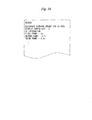
- Fig. 2 illustrates the header of a file (a file containing stereoscopic moving image data) in which cross-point (CP) information has been recorded.
- the cross-point information may just as well be recorded in an image data recording area of the file and not in the header.
- Cross points of first, second and third frames constituting a stereoscopic moving image are at 2 m, 2.1 m and 2.3 m, respectively, and these items of cross-point information have been recorded on the memory card 59.
- Cross-point information has been recorded with regard to other frames as well.
- the stereoscopic imaging digital camera also has a playback function.
- Stereoscopic moving image data representing a stereoscopic moving image recorded on the memory card 40 is read from the memory card 40 via the media interface 35.
- the stereoscopic moving image data that has been read is applied to the liquid crystal display device 33.
- the stereoscopic moving image represented by the stereoscopic moving image data is displayed on the display screen of the liquid crystal display device 33.
- the stereoscopic imaging digital camera can also be connected to the external display unit 41, and the stereoscopic moving image represented by the stereoscopic moving image data that has been recorded on the memory card 40 can also be displayed on the external display unit 41.
- the stereoscopic moving image data that has been read from the memory card 40 is applied to the external display unit 41 via the input/output interface 39.
- the stereoscopic moving image is displayed on the external display unit 41 as a result.
- an image portion representing a subject at a position deeper than the cross point in the stereoscopic image is caused to blur. Since the image portion representing the subject at this deep position is blurred in this manner, the observer can be prevented from closely observing this image portion. Since blurring is not applied to an image portion representing a subject at a position shallower than the cross point in the stereoscopic image, the image is displayed stereoscopically. Since the display screen of the liquid crystal display device 33 provided on the back of the stereoscopic imaging digital camera is comparatively small, there is not a large amount of parallax.
- the blurring processing can utilize a smoothing filter and can also be implemented by software.
- the stereoscopic imaging digital camera is provided with a blurring processing unit 42 in order to execute blurring processing.
- Fig. 3 is an example of a reproduced stereoscopic image.
- This stereoscopic image 50 is represented by superimposing an image for the left eye and an image for the right eye.
- the left-eye image and right-eye image may be superimposed simultaneously, or it will suffice if the left-eye image and right-eye image can be seen by the observer in essentially superimposed form by displaying them with a temporal shift.
- the stereoscopic image 50 contains a first area 51 at the upper left, a second area 52 at the upper right and a third area 53 in front.
- the second area 52 is an area in which the cross point is located.
- the first area 51 is an area farther (deeper) than the cross point, and the third area 53 is an area nearer (shallower) than the cross point.
- the second area 52 includes an image 52A of a tree. Since the second area 52 is the area having the cross point, the image 52A of the tree is devoid of parallax (this image is not expressed by images offset to the left and right).
- the first area 51 includes tree images 51L and 51R offset to the left and right. One tree image 51L is represented by an image for the left eye, and the other tree image 51R is represented by an image for the right eye. Parallax is produced between the tree images 51L and 51R.
- the third area 53 includes person images 53L and 53R offset to the left and right. One person image 53L is represented by an image for the left eye, and the other person image 53R is represented by an image for the right eye. In this background example, blurring processing is applied to the images 51L and 51R representing a subject farther than the cross point.
- Parallax is utilized in order to find an image portion farther than the cross point in the stereoscopic image.
- Fig. 4 is an example of a stereoscopic image for describing parallax. Items in Fig. 4 identical with those shown in Fig. 3 are designated by like reference characters and a description thereof is omitted.
- Such processing is executed with regard to the entirety of the stereoscopic image 50 and an image portion representing a subject farther (deeper) than the cross point and an image portion representing a subject nearer (shallower) than the cross point are found in the stereoscopic image 50.
- processing may be executed at one pixel or at a plurality of pixels within this area and an image within the area may be judged to be farther than or nearer than the cross point depending upon the result.
- Fig. 5 is an example of a reproduced stereoscopic image.
- the second area 52 is an area of the cross point
- the first area 51 is an area representing the subject farther than the cross point
- the third area 53 is an area nearer than the cross point. Since the first area 51 is an area representing the subject farther than the cross point, the images 51R and 51L within the area 51 have been caused to blur. As a result, the observer can be prevented from closely observing the images 51R and 51L within the area 51.
- Fig. 6 is a flowchart illustrating a playback processing procedure.
- the stereoscopic imaging digital camera and the external display apparatus (e.g., a television apparatus) 41 are connected and begin communicating (step 61).
- Cross-point information and stereoscopic moving image data are read from the memory card 40 (step 62).
- an image portion farther than the cross point is found and blurring processing is applied to the image portion found (step 63), as described above.
- Stereoscopic images blurred with regard to image portions farther than the cross point are displayed successively on the external display unit 41, whereby a stereoscopic moving image is displayed (step 64).
- the background example described above concerns a stereoscopic moving image
- the invention is not limited to a stereoscopic moving image and similar processing can be applied to a stereoscopic still image as well.
- Figs. 7 to 9 illustrate another background example.
- an image portion representing a subject at a position farther than the cross point is caused to blur.
- the farther an image portion is from the cross point the greater the amount of blurring applied.
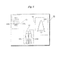
- Fig. 7 illustrates an example of a reproduced stereoscopic image. Items in Fig. 7 identical with those shown in Fig. 3 are designated by like reference characters and a description thereof is omitted.
- a stereoscopic image 60 contains a fourth area 54 in addition to the first area 51, second area 52 and third area 53.
- the fourth area 54 includes an image 54L of a tree for the left eye and an image 54R of the tree for the right eye.
- a subject represented by these images 54L and 54R is located at a position farther than the subject represented by the images 51L and 51R included in the first area 51.
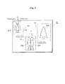
- Fig. 8 is an example of a stereoscopic image that has been subjected to blurring processing.
- the tree images 51L and 51R within the first area 51 and the tree images 54L and 54R within the second area 54 which represent subjects farther than the cross point, have all been blurred.
- the subject represented by the tree images 54L and 54R within the second area 54 is farther than the subject represented by the tree images 51L and 51R within the first area 51, the amount of blurring applied to it is greater.
- Fig. 9 which corresponds to Fig. 6 , is a flowchart illustrating a playback processing procedure. Processing in Fig. 9 identical with that shown in Fig. 6 is designated by like reference characters and a description thereof is omitted.
- Cross-point information, stereoscopic moving image data and information representing parallax are read from the memory card 40 (steps 62, 65).
- step 66 it is judged whether blurring processing is that of a first stage (step 66). Whether blurring processing is that of a first stage is decided by a setting made at the operation unit 34. If blurring processing has been set to a first stage by the operation unit 34 ("YES" at step 66), then image portions representing subjects far from the cross point are subjected to uniform blurring processing (step 63) in the manner described above. If blurring processing has not been set to the first stage by the operation unit 34 ("NO" at step 66), then blurring processing is executed in such a manner that the more an image portion represents a subject deeper than the cross point, the more the amount of blurring is increased (step 67).
- Figs. 10 to 12 illustrate an embodiment. This embodiment changes the amount of blurring in accordance with the size of the display screen that displays the stereoscopic image.
- the amount of blurring may just as well be changed in accordance with the display screen size while changing the amount of blurring the deeper an image portion is from the cross point in the manner described above.
- Fig. 10 illustrates the contents of the header of a file in which the above-mentioned cross-point information has been recorded.
- a reference amount of blurring with respect to a prescribed display screen size has been stored in addition to the above-mentioned cross-point information.
- a reference amount of blurring is represented by D in case of a 42-inch display screen size.
- Figs. 11a and 11b are examples of reproduced stereoscopic images. Items in these figures identical with those shown in Fig. 8 are designated by like reference characters and a description thereof is omitted.
- Fig. 11a is the example of the stereoscopic image 60 displayed on the display screen of a 37-inch
- Fig. 11b is the example of the stereoscopic image 60 displayed on the display screen of a 42-inch.
- the amount of blurring prevailing when a stereoscopic image is displayed on the 42-inch display screen is the blurring amount D, as mentioned above, then the amount of blurring that prevails when the stereoscopic image is displayed on a 37-inch display screen will be (37-inch size / 42-inch size) x D.
- Fig. 12 which corresponds to Fig. 6 , is a flowchart illustrating a playback processing procedure. Processing in Fig. 12 identical with that shown in Fig. 6 is designated by like reference characters and a description thereof is omitted.
- the stereoscopic imaging digital camera and the external display apparatus 41 are connected, size information representing the size of the display screen of external display unit 41 is read from the external display unit 41 and a reference blurring amount that has been recorded on the memory card 40 is read (step 68).
- a cross point that matches the size of the display screen represented by the read size information is calculated.
- the image for the left eye and the image for the right eye are adjusted in such a manner that the parallax at the calculated cross point vanishes.
- a blurring amount matching the display screen that displays the stereoscopic image is calculated from the read reference blurring amount.
- a subject located at a position farther than the calculated cross point is caused to blur at the blurring amount calculated from the reference blurring amount (step 69).
- a cross point is calculated in accordance with the size of the display screen and images for the left and right eyes are adjusted in such a manner that the parallax at the calculated cross point vanishes. Also, so that a blurring amount conforming to the size of the display screen is applied based upon the read reference blurring amount without calculating a cross point conforming to the display screen and without adjusting the images for the left and right eyes.
- Figs. 13 and 14 illustrate another embodiment. This embodiment changes the cross point at the time of playback.
- Fig. 13 is an example of a stereoscopic image displayed on a display screen.
- a stereoscopic image 60A contains the first area 51, second area 52, third area 53 and fourth area 54 in a manner similar to the stereoscopic image 60 shown in Fig. 8 .
- the second area 52 contains the cross point and the tree image 52A devoid of parallax is being displayed.
- the cross point has been moved to the third area 53 that represents a subject shallower than the subject represented by the image portion contained in the second area 52.
- the tree images 52L and 52R within the second area 52 become overlapping images and the person image 53A within the third area 53 becomes an image devoid of parallax.
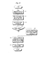
- Fig. 14 is a flowchart illustrating a playback processing procedure.
- the stereoscopic imaging digital camera and the external display apparatus 41 are connected and begin communicating (step 61).
- Stereoscopic moving image data that has been recorded on the memory card 40 is read (step 71).
- cross-point information and reference blurring amount with respect to display screen size for every stereoscopic image constituting the stereoscopic moving image are read from the header of the file containing the stereoscopic moving image data (step 72).
- parallax information for every stereoscopic image also is read from the file (step 73). It goes without saying that the parallax information is generated at the time of recording of the stereoscopic moving image data and that it has been stored in the file header along with the cross-point information and reference blurring amount. Naturally, it may be arranged so that the parallax information is generated at the time of playback without being recorded beforehand.
- parallax is outside the allowed range if the parallax is equal to or greater than a prescribed threshold value, and that parallax is within the allowed range if the parallax is less than the prescribed threshold value.
- parallax is not within the allowed range ("NO" at step 74)
- the cross point is moved toward the short-distance side (shallower) (step 75).
- Parallax of an image portion representing a shallow subject vanishes, as illustrated in Fig. 13 .
- the image portion representing a subject farther than the cross point at the time of recording is caused to blur in accordance with amount of parallax and the display screen size of the external display unit (step 76).
- the image portion representing the subject farther than this cross point is caused to blur in accordance with the amount of parallax and display screen size of the external display unit (step 76).
- step 77 If processing regarding the stereoscopic images of all frames that constitute the stereoscopic image is not finished ("NO" at step 77), then the stereoscopic imaging digital camera is controlled in such a manner that similar processing is applied to the stereoscopic image of the next frame (step 78), and the processing of steps 74 to 76 is repeated.
- the stereoscopic moving image is displayed (step 64).
- Figs. 15 to 21 illustrate another embodiment. This embodiment arranges it so that in a case where the scene of a stereoscopic moving image changes, the observer will not be given an impression of a sudden change in scene.
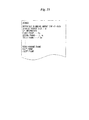
- Fig. 15 illustrates the contents of a header.
- a scene-change frame representing a frame in which the scene changes over has been recorded in the header in addition to the cross-point information.
- a 134 th frame is a scene-change frame and there is a changeover between the scene of the stereoscopic moving image extending up to the 133 rd frame and the scene of the stereoscopic moving image from the 134 th frame onward.
- Fig. 16 is a time chart representing scenes of a stereoscopic moving image.
- Frames from the first frame to the 133 rd frame constitute the stereoscopic moving image of a scene A, and frames from the 134 th frame onward constitute the stereoscopic moving image of a scene B.
- Fig. 17 is a time chart illustrating the timing at which stereoscopic images before and after the scene changeover of the stereoscopic moving image are caused to blur in their entirety.
- stereoscopic images are displayed upon being blurred in their entirety over a total of two seconds, namely one second before and one second after the scene-change frame. Since the stereoscopic images before and after the scene change are blurred entirely, the observer is not imparted with a sense of oddness even though the scene changes.
- Fig. 18 illustrates an example of stereoscopic images.
- Fig. 19 which illustrates a modification, is a time chart illustrating the timing at which stereoscopic images before and after a scene changeover of a stereoscopic moving image are caused to blur in their entirety.
- stereoscopic images are caused to blur entirely before and after the scene changes over.
- stereoscopic images of a plurality of frames preceding the changeover of the scene are displayed in gradually decreasing size, and stereoscopic images of a plurality of frames following the scene changeover gradually increase in size and take on the original size of the stereoscopic image.
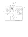
- Fig. 20 illustrates the manner in which the size of stereoscopic images changes before and after a scene changes over.
- stereoscopic images of a plurality of frames preceding the changeover of the scene gradually decrease in size from an original size 60B of the stereoscopic image, and the image of the frame immediately preceding the scene changeover or of the frame in which the scene changes over takes on the smallest size 60C. After the scene changes over, the sizes of the images gradually increase and take on the size 60B of the original stereoscopic image.
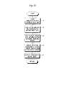
- Fig. 21 which corresponds to Fig. 6 , is a flowchart illustrating a playback processing procedure. Processing in Fig. 21 identical with that shown in Fig. 6 is designated by like reference characters and a description thereof is omitted.
- Step 101 Scene-change information that has been recorded on the memory card 40 is read (step 101).
- processing such as processing for blurring in their entirety stereoscopic images before and after the scene changeover and for reducing and enlarging stereoscopic images, as described above, is executed (step 104). Thereafter, processing for blurring an image portion representing a subject farther than the cross point is executed (step 69), as described above. If there is no scene changeover ("NO" at step 102), then step 104 is skipped.
- the processing shown in Fig. 6 , the processing shown in Fig. 9 , the processing shown in Fig. 12 , the processing shown in Fig. 14 and the processing shown in Fig. 21 appear in the drawings as processes that are separate from one another. However, any number of these processes may be combined. For example, from among the processing shown in Fig. 9 , the processing shown in Fig. 12 , the processing shown in Fig. 14 and the processing shown in Fig. 21 , one or any number of the processes may be combined with the processing shown in Fig. 6 ; from among the processing shown in Fig. 12 , the processing shown in Fig. 14 and the processing shown in Fig.
- one or any number of the processes may be combined with the processing shown in Fig. 9 ; either or both of the processing shown in Figs. 14 and 21 may be combined with the processing shown in Fig. 12 ; and the processing shown in Fig. 14 and the processing shown in Fig. 21 may be combined.
- a stereoscopic image is caused to blur in such a manner that the deeper an image portion relative to a cross point, the larger the amount of blurring becomes.
- it may be arranged so that the shallower an image portion relative to a cross point, the more the stereoscopic image is caused to blur.
- the processing for blurring a stereoscopic image more the shallower an image portion is relative to the cross point may just as well be executed in the above-mentioned processing shown in Fig. 9 , processing shown in Fig. 12 , processing shown in Fig. 14 or processing shown in Fig. 21 , or it may be executed in any combination of these. It goes without saying that such blurring processing can be implemented using a smoothing filter.
Landscapes
- Engineering & Computer Science (AREA)
- Multimedia (AREA)
- Signal Processing (AREA)
- Library & Information Science (AREA)
- Testing, Inspecting, Measuring Of Stereoscopic Televisions And Televisions (AREA)
- Processing Or Creating Images (AREA)
- Image Processing (AREA)
- Television Signal Processing For Recording (AREA)
Claims (5)
- Eine Stereoskopbildanzeige-Steuervorrichtung umfassend:eine Stereoskopilddaten-Leseeinheit (35) zum Lesen von Stereoskopilddaten, welche ein Stereoskopbild darstellen und welche auf einem Speichermedium (40) gespeichert wurden;eine Kreuzungspunktinformation-Leseeinheit zum Lesen einer Kreuzungspunktinformation, welche auf dem Speichermedium gespeichert wurde und welche einen Kreuzungspunkt darstellt, wobei der Kreuzungspunkt eine Tiefe angibt, bei welcher keine Parallaxe in dem Stereoskopbild erzeugt ist;eine Parallaxe-Bestimmungseinheit (38) zum Bestimmen, ob eine Parallaxe eines ersten Bildteils, welcher ein Objekt bei einer flacheren Tiefe als der Kreuzungspunkt in dem Stereoskopbild darstellt, gleich oder größer als ein Schwellenwert ist;gekennzeichnet durcheine Kreuzungspunkt-Steuereinheit zum Steuern der Stereoskopbilddaten, wobei, falls durch die Parallaxe-Bestimmungseinheit bestimmt ist, dass die Parallaxe des ersten Bildteils gleich oder größer als der Schwellenwert ist, die Kreuzungspunkt-Steuereinheit zum Verschieben des Kreuzungspunkts zu einer flacheren Tiefe ausgebildet ist;eine erste Verwischungseinheit (42) zum Verwischen eines zweiten Bildteils, welcher ein Objekt bei einer tieferen Tiefe als der verschobene Kreuzungspunkt darstellt, derart, dass je tiefer das Objekt relativ zu dem verschobenen Kreuzungspunkt ist, desto größer der Betrag des Verwischens wird, und zum Verwischen des zweiten Bildteils derart, dass je größer ein Anzeigebildschirm einer Anzeigevorrichtung (41) ist, desto größer der Betrag eines Verwischens wird; undeine Anzeige-Steuereinheit (39) zum Steuern der Anzeigevorrichtung (41) derart, dass das Stereoskopbild angezeigt wird, bei welchem der zweite Bildteil, welcher das Objekt bei der tieferen Position als der verschobene Kreuzungspunkt darstellt, durch die erste Verwischungseinheit (42) verwischt ist.
- Eine Stereoskopbildanzeige-Steuervorrichtung gemäß Anspruch 1, wobei das Stereoskopbild ein Bild eines einzelnen ein Stereoskopbewegtbild bildenden Frames ist, wobei die Stereoskopbilddaten-Leseeinheit zum Lesen von Stereoskopbilddaten, welche Stereoskopbilder einer Anzahl von Frames darstellen, von dem Speichermedium (40) und von Szenenänderungsinformationen, welche einen Frame des Stereoskopbilds darstellen, wobei eine Szene der Stereoskopbildänderungen auf dem Speichermedium (40) gespeichert wurde, ausgebildet ist, wobei die Vorrichtung weiter umfasst:eine Szenenänderungsinformationen-Leseeinheit zum Lesen der Szenenänderungsinformationen von dem Speichermedium (40); undeine zweite Verwischungseinheit (42) zum Verwischen der Gesamtheit der Stereoskopbilder von Szenenänderungsframes, welche ein oder eine Vielzahl von Frames sind, welche einem Frame des durch die Szenenänderungsinformationen-Leseeinheit ausgelesenen Szenenänderungsinformationen wiedergegebenen Stereoskopbilds vorangehen und nachfolgen;wobei die Anzeige-Steuereinheit (39) zum Steuern der Anzeigevorrichtung (41) derart ausgebildet ist, dass Stereoskopbilder, welche durch die erste Verwischungseinheit (42) verwischt wurden, mit Bezug zu den Stereoskopbildern oder Frames außer den Szeneänderungsframes angezeigt werden, und dass die Stereoskopbilder, welche durch die erste und zweite Verwischungseinheit (42) verwischt wurden, mit Bezug zu den Stereoskopbildern der Szenenänderungsframes angezeigt werden.
- Eine Stereoskopbildanzeige-Steuervorrichtung gemäß Anspruch 2, wobei die Anzeige-Steuereinheit (39) zum Steuern der Anzeigevorrichtung (41) derart ausgebildet ist, dass die Stereoskopbilder derart angezeigt werden, dass Stereoskopbilder der Szenenänderungsframes bis zu einem Stereoskopbild, welches dem Stereoskopbild, bei welchem die Szene des Stereoskopbild sich ändert, vorangeht, graduell von klein bis groß reduziert werden und dem Stereoskopbild, bei welchem die Szene des Stereoskopbild sich ändert, nachfolgend von klein zu groß graduell vergrößert werden.
- Eine Stereoskopbildanzeige-Steuervorrichtung gemäß Anspruch 3, wobei die zweite Verwischungseinheit (42) weiter zum Verwischen eines Bildteils, welcher ein Objekt bei einer flacheren Position als der durch durch die Kreuzungspunktinformation-Leseeinheit ausgelesenen Kreuzungspunktinformationen dargestellte Kreuzungspunkt darstellt, in dem durch durch die Stereoskopbilddaten-Leseeinheit ausgelesenen Stereoskopbilddaten dargestellten Stereoskopbild derart ausgebildet ist, dass je flacher das Objekt relativ zu dem Kreuzungspunkt ist, desto größer der Betrag des Verwischens wird.
- Ein Verfahren zum Steuern eines Betriebs einer Stereoskopbildanzeige-Vorrichtung, umfassend:Lesen (71), durch eine Stereoskopbilddaten-Leseeinheit, von Stereoskopbilddaten, welche ein Stereoskopbild darstellen und welche auf einem Speichermedium (40) gespeichert wurden;Lesen (72), durch eine Kreuzungspunktinformationen-Leseeinheit, von Kreuzungspunktinformationen, welche auf dem Speichermedium (40) gespeichert wurden und welche einen Kreuzungspunkt darstellen, wobei der Kreuzungspunkt eine Tiefe angibt, bei welcher keine Parallaxe in dem Stereoskopbild erzeugt wird;Bestimmen (74), durch eine Parallaxe-Bestimmungseinheit, ob eine Parallaxe eines ersten Bildteils, welcher ein Objekt bei einer flacheren Tiefe als der Kreuzungspunkt in dem Stereoskopbild darstellt, gleich oder größer als ein Schwellenwert ist;gekennzeichnet durchSteuern (75), durch eine Kreuzungspunkt-Steuereinheit, der Stereoskopbilddaten, wobei, falls durch die Parallaxe-Bestimmungseinheit bestimmt ist, dass die Parallaxe des ersten Bildteils gleich oder größer als der Schwellenwert ist, der Kreuzungspunkt zu einer flacheren Tiefe verschoben wird;Verwischen (76), durch eine erste Verwischungseinheit (42), eines zweiten Bildteils, welcher ein Objekt bei einer tieferen Tiefe als der verschobene Kreuzungspunkt darstellt, derart, dass je tiefer das Objekt relativ zu dem verschobenen Kreuzungspunkt ist, desto größer der Betrag des Verwischens wird, und ein Verwischen, durch die erste Verwischungseinheit (42), des zweiten Bildteils derart, dass je größer ein Anzeigebildschirm der Anzeigevorrichtung ist, desto größer der Betrag des Verwischens wird; undSteuern (64), durch eine Anzeige-Steuereinheit (39), einer Anzeigevorrichtung (41) derart, dass das Stereoskopbild, bei welchem der zweite Bildteil, welcher das Objekt bei einer tieferen Tiefe als der verschobene Kreuzungspunkt darstellt, durch die erste Verwischungseinheit (42) verwischt wurde, angezeigt wird.
Applications Claiming Priority (2)
| Application Number | Priority Date | Filing Date | Title |
|---|---|---|---|
| JP2010138100 | 2010-06-17 | ||
| PCT/JP2011/060681 WO2011158573A1 (ja) | 2010-06-17 | 2011-04-27 | 立体画像表示制御装置およびその動作制御方法 |
Publications (3)
| Publication Number | Publication Date |
|---|---|
| EP2469876A1 EP2469876A1 (de) | 2012-06-27 |
| EP2469876A4 EP2469876A4 (de) | 2013-06-05 |
| EP2469876B1 true EP2469876B1 (de) | 2015-07-29 |
Family
ID=45347984
Family Applications (1)
| Application Number | Title | Priority Date | Filing Date |
|---|---|---|---|
| EP11795481.8A Not-in-force EP2469876B1 (de) | 2010-06-17 | 2011-04-27 | Vorrichtung zur Steuerung einer stereoskopischen Bildanzeige und Betriebssteuerverfahren dafür |
Country Status (5)
| Country | Link |
|---|---|
| US (1) | US8472786B2 (de) |
| EP (1) | EP2469876B1 (de) |
| JP (1) | JP4989788B2 (de) |
| CN (1) | CN102656892B (de) |
| WO (1) | WO2011158573A1 (de) |
Families Citing this family (7)
| Publication number | Priority date | Publication date | Assignee | Title |
|---|---|---|---|---|
| JP4787369B1 (ja) * | 2010-03-30 | 2011-10-05 | 富士フイルム株式会社 | 画像処理装置および方法並びにプログラム |
| JP5572647B2 (ja) * | 2012-02-17 | 2014-08-13 | 任天堂株式会社 | 表示制御プログラム、表示制御装置、表示制御システム、および表示制御方法 |
| JP5564633B2 (ja) * | 2012-02-23 | 2014-07-30 | 富士フイルム株式会社 | 立体画像表示制御装置、これを備える撮像装置、及び立体画像表示制御方法 |
| US8937644B2 (en) * | 2012-03-21 | 2015-01-20 | Canon Kabushiki Kaisha | Stereoscopic image capture |
| JP2014236340A (ja) * | 2013-05-31 | 2014-12-15 | 株式会社東芝 | 画像処理装置、方法、及びプログラム、並びに、立体画像表示装置 |
| CN105100772B (zh) * | 2015-07-16 | 2017-03-15 | 深圳市华星光电技术有限公司 | 一种三维图像处理方法及装置 |
| US10078228B2 (en) | 2016-09-29 | 2018-09-18 | Jeremy Paul Willden | Three-dimensional imaging system |
Citations (1)
| Publication number | Priority date | Publication date | Assignee | Title |
|---|---|---|---|---|
| WO2010046824A1 (en) * | 2008-10-21 | 2010-04-29 | Koninklijke Philips Electronics N.V. | Method and system for processing an input three dimensional video signal |
Family Cites Families (11)
| Publication number | Priority date | Publication date | Assignee | Title |
|---|---|---|---|---|
| JPH04343685A (ja) | 1991-05-20 | 1992-11-30 | Mitsubishi Electric Corp | 産業用ロボットの駆動装置 |
| JP3182009B2 (ja) * | 1992-12-24 | 2001-07-03 | 日本電信電話株式会社 | 両眼立体視装置 |
| JPH0943468A (ja) | 1995-08-02 | 1997-02-14 | Fujikura Ltd | 光ファイバケーブル及びその製造方法 |
| JP3787939B2 (ja) | 1997-02-27 | 2006-06-21 | コニカミノルタホールディングス株式会社 | 立体映像表示装置 |
| JPH11355624A (ja) | 1998-06-05 | 1999-12-24 | Fuji Photo Film Co Ltd | 撮影装置 |
| JP2001326947A (ja) * | 2000-05-12 | 2001-11-22 | Sony Corp | 立体画像表示装置 |
| US7417664B2 (en) | 2003-03-20 | 2008-08-26 | Seijiro Tomita | Stereoscopic image picking up and display system based upon optical axes cross-point information |
| US7679641B2 (en) * | 2006-04-07 | 2010-03-16 | Real D | Vertical surround parallax correction |
| WO2008126200A1 (ja) | 2007-03-23 | 2008-10-23 | Ntt Comware Corporation | 立体画像処理装置およびプログラム |
| JP4695664B2 (ja) * | 2008-03-26 | 2011-06-08 | 富士フイルム株式会社 | 立体動画像処理装置および方法並びにプログラム |
| EP2286385A4 (de) * | 2008-06-06 | 2013-01-16 | Reald Inc | Trübungsverstärkung stereoskopischer bilder |
-
2011
- 2011-04-27 EP EP11795481.8A patent/EP2469876B1/de not_active Not-in-force
- 2011-04-27 WO PCT/JP2011/060681 patent/WO2011158573A1/ja not_active Ceased
- 2011-04-27 JP JP2011554288A patent/JP4989788B2/ja not_active Expired - Fee Related
- 2011-04-27 US US13/498,315 patent/US8472786B2/en not_active Expired - Fee Related
- 2011-04-27 CN CN201180004972.2A patent/CN102656892B/zh not_active Expired - Fee Related
Patent Citations (1)
| Publication number | Priority date | Publication date | Assignee | Title |
|---|---|---|---|---|
| WO2010046824A1 (en) * | 2008-10-21 | 2010-04-29 | Koninklijke Philips Electronics N.V. | Method and system for processing an input three dimensional video signal |
Also Published As
| Publication number | Publication date |
|---|---|
| US8472786B2 (en) | 2013-06-25 |
| EP2469876A4 (de) | 2013-06-05 |
| EP2469876A1 (de) | 2012-06-27 |
| CN102656892A (zh) | 2012-09-05 |
| WO2011158573A1 (ja) | 2011-12-22 |
| US20120237179A1 (en) | 2012-09-20 |
| JPWO2011158573A1 (ja) | 2013-08-19 |
| CN102656892B (zh) | 2015-03-25 |
| JP4989788B2 (ja) | 2012-08-01 |
Similar Documents
| Publication | Publication Date | Title |
|---|---|---|
| JP5963422B2 (ja) | 撮像装置、表示装置、コンピュータプログラムおよび立体像表示システム | |
| EP2469876B1 (de) | Vorrichtung zur Steuerung einer stereoskopischen Bildanzeige und Betriebssteuerverfahren dafür | |
| JP5978573B2 (ja) | 映像信号処理装置および映像信号処理方法 | |
| US20130038611A1 (en) | Image conversion device | |
| US20130162764A1 (en) | Image processing apparatus, image processing method, and non-transitory computer-readable medium | |
| EP2555525B1 (de) | Abbildungsvorrichtung für ein facettenauge sowie disparitätseinstellungsverfahren und -programm dafür | |
| CN102986232B (zh) | 图像处理装置及方法 | |
| CN102972036B (zh) | 重放装置、复眼摄像装置、重放方法及程序 | |
| JP5449551B2 (ja) | 画像出力装置、方法およびプログラム | |
| EP2434766A2 (de) | Anpassung von 3D-Videoinhalt | |
| JP5580486B2 (ja) | 画像出力装置、方法およびプログラム | |
| JP5571257B2 (ja) | 画像処理装置、方法およびプログラム | |
| JP2012015620A (ja) | 立体撮像装置 | |
| JP2012227653A (ja) | 撮像装置及び撮像方法 | |
| JP5507003B2 (ja) | 立体画像処理装置及び立体画像処理方法 | |
| JPWO2012001958A1 (ja) | 画像処理装置および方法並びにプログラム | |
| JP2011223540A (ja) | 立体動画処理装置およびその動作制御方法 | |
| JP2012023676A (ja) | 立体画像処理装置及び立体画像表示装置 |
Legal Events
| Date | Code | Title | Description |
|---|---|---|---|
| PUAI | Public reference made under article 153(3) epc to a published international application that has entered the european phase |
Free format text: ORIGINAL CODE: 0009012 |
|
| 17P | Request for examination filed |
Effective date: 20120320 |
|
| AK | Designated contracting states |
Kind code of ref document: A1 Designated state(s): AL AT BE BG CH CY CZ DE DK EE ES FI FR GB GR HR HU IE IS IT LI LT LU LV MC MK MT NL NO PL PT RO RS SE SI SK SM TR |
|
| REG | Reference to a national code |
Ref country code: DE Ref legal event code: R079 Ref document number: 602011018321 Country of ref document: DE Free format text: PREVIOUS MAIN CLASS: H04N0013040000 Ipc: H04N0013000000 |
|
| A4 | Supplementary search report drawn up and despatched |
Effective date: 20130506 |
|
| RIC1 | Information provided on ipc code assigned before grant |
Ipc: H04N 13/00 20060101AFI20130426BHEP |
|
| DAX | Request for extension of the european patent (deleted) | ||
| 17Q | First examination report despatched |
Effective date: 20140116 |
|
| GRAP | Despatch of communication of intention to grant a patent |
Free format text: ORIGINAL CODE: EPIDOSNIGR1 |
|
| INTG | Intention to grant announced |
Effective date: 20150305 |
|
| GRAS | Grant fee paid |
Free format text: ORIGINAL CODE: EPIDOSNIGR3 |
|
| GRAA | (expected) grant |
Free format text: ORIGINAL CODE: 0009210 |
|
| AK | Designated contracting states |
Kind code of ref document: B1 Designated state(s): AL AT BE BG CH CY CZ DE DK EE ES FI FR GB GR HR HU IE IS IT LI LT LU LV MC MK MT NL NO PL PT RO RS SE SI SK SM TR |
|
| REG | Reference to a national code |
Ref country code: GB Ref legal event code: FG4D |
|
| REG | Reference to a national code |
Ref country code: CH Ref legal event code: EP |
|
| REG | Reference to a national code |
Ref country code: AT Ref legal event code: REF Ref document number: 740054 Country of ref document: AT Kind code of ref document: T Effective date: 20150815 |
|
| REG | Reference to a national code |
Ref country code: IE Ref legal event code: FG4D |
|
| REG | Reference to a national code |
Ref country code: DE Ref legal event code: R096 Ref document number: 602011018321 Country of ref document: DE |
|
| REG | Reference to a national code |
Ref country code: AT Ref legal event code: MK05 Ref document number: 740054 Country of ref document: AT Kind code of ref document: T Effective date: 20150729 |
|
| REG | Reference to a national code |
Ref country code: LT Ref legal event code: MG4D |
|
| REG | Reference to a national code |
Ref country code: NL Ref legal event code: MP Effective date: 20150729 |
|
| PG25 | Lapsed in a contracting state [announced via postgrant information from national office to epo] |
Ref country code: NO Free format text: LAPSE BECAUSE OF FAILURE TO SUBMIT A TRANSLATION OF THE DESCRIPTION OR TO PAY THE FEE WITHIN THE PRESCRIBED TIME-LIMIT Effective date: 20151029 Ref country code: FI Free format text: LAPSE BECAUSE OF FAILURE TO SUBMIT A TRANSLATION OF THE DESCRIPTION OR TO PAY THE FEE WITHIN THE PRESCRIBED TIME-LIMIT Effective date: 20150729 Ref country code: GR Free format text: LAPSE BECAUSE OF FAILURE TO SUBMIT A TRANSLATION OF THE DESCRIPTION OR TO PAY THE FEE WITHIN THE PRESCRIBED TIME-LIMIT Effective date: 20151030 Ref country code: LT Free format text: LAPSE BECAUSE OF FAILURE TO SUBMIT A TRANSLATION OF THE DESCRIPTION OR TO PAY THE FEE WITHIN THE PRESCRIBED TIME-LIMIT Effective date: 20150729 Ref country code: LV Free format text: LAPSE BECAUSE OF FAILURE TO SUBMIT A TRANSLATION OF THE DESCRIPTION OR TO PAY THE FEE WITHIN THE PRESCRIBED TIME-LIMIT Effective date: 20150729 |
|
| PG25 | Lapsed in a contracting state [announced via postgrant information from national office to epo] |
Ref country code: SE Free format text: LAPSE BECAUSE OF FAILURE TO SUBMIT A TRANSLATION OF THE DESCRIPTION OR TO PAY THE FEE WITHIN THE PRESCRIBED TIME-LIMIT Effective date: 20150729 Ref country code: AT Free format text: LAPSE BECAUSE OF FAILURE TO SUBMIT A TRANSLATION OF THE DESCRIPTION OR TO PAY THE FEE WITHIN THE PRESCRIBED TIME-LIMIT Effective date: 20150729 Ref country code: PL Free format text: LAPSE BECAUSE OF FAILURE TO SUBMIT A TRANSLATION OF THE DESCRIPTION OR TO PAY THE FEE WITHIN THE PRESCRIBED TIME-LIMIT Effective date: 20150729 Ref country code: RS Free format text: LAPSE BECAUSE OF FAILURE TO SUBMIT A TRANSLATION OF THE DESCRIPTION OR TO PAY THE FEE WITHIN THE PRESCRIBED TIME-LIMIT Effective date: 20150729 Ref country code: HR Free format text: LAPSE BECAUSE OF FAILURE TO SUBMIT A TRANSLATION OF THE DESCRIPTION OR TO PAY THE FEE WITHIN THE PRESCRIBED TIME-LIMIT Effective date: 20150729 Ref country code: PT Free format text: LAPSE BECAUSE OF FAILURE TO SUBMIT A TRANSLATION OF THE DESCRIPTION OR TO PAY THE FEE WITHIN THE PRESCRIBED TIME-LIMIT Effective date: 20151130 Ref country code: ES Free format text: LAPSE BECAUSE OF FAILURE TO SUBMIT A TRANSLATION OF THE DESCRIPTION OR TO PAY THE FEE WITHIN THE PRESCRIBED TIME-LIMIT Effective date: 20150729 Ref country code: IS Free format text: LAPSE BECAUSE OF FAILURE TO SUBMIT A TRANSLATION OF THE DESCRIPTION OR TO PAY THE FEE WITHIN THE PRESCRIBED TIME-LIMIT Effective date: 20151129 |
|
| PG25 | Lapsed in a contracting state [announced via postgrant information from national office to epo] |
Ref country code: NL Free format text: LAPSE BECAUSE OF FAILURE TO SUBMIT A TRANSLATION OF THE DESCRIPTION OR TO PAY THE FEE WITHIN THE PRESCRIBED TIME-LIMIT Effective date: 20150729 |
|
| PG25 | Lapsed in a contracting state [announced via postgrant information from national office to epo] |
Ref country code: DK Free format text: LAPSE BECAUSE OF FAILURE TO SUBMIT A TRANSLATION OF THE DESCRIPTION OR TO PAY THE FEE WITHIN THE PRESCRIBED TIME-LIMIT Effective date: 20150729 Ref country code: IT Free format text: LAPSE BECAUSE OF FAILURE TO SUBMIT A TRANSLATION OF THE DESCRIPTION OR TO PAY THE FEE WITHIN THE PRESCRIBED TIME-LIMIT Effective date: 20150729 Ref country code: SK Free format text: LAPSE BECAUSE OF FAILURE TO SUBMIT A TRANSLATION OF THE DESCRIPTION OR TO PAY THE FEE WITHIN THE PRESCRIBED TIME-LIMIT Effective date: 20150729 Ref country code: EE Free format text: LAPSE BECAUSE OF FAILURE TO SUBMIT A TRANSLATION OF THE DESCRIPTION OR TO PAY THE FEE WITHIN THE PRESCRIBED TIME-LIMIT Effective date: 20150729 Ref country code: CZ Free format text: LAPSE BECAUSE OF FAILURE TO SUBMIT A TRANSLATION OF THE DESCRIPTION OR TO PAY THE FEE WITHIN THE PRESCRIBED TIME-LIMIT Effective date: 20150729 |
|
| REG | Reference to a national code |
Ref country code: DE Ref legal event code: R097 Ref document number: 602011018321 Country of ref document: DE |
|
| PG25 | Lapsed in a contracting state [announced via postgrant information from national office to epo] |
Ref country code: RO Free format text: LAPSE BECAUSE OF FAILURE TO SUBMIT A TRANSLATION OF THE DESCRIPTION OR TO PAY THE FEE WITHIN THE PRESCRIBED TIME-LIMIT Effective date: 20150729 |
|
| PLBE | No opposition filed within time limit |
Free format text: ORIGINAL CODE: 0009261 |
|
| STAA | Information on the status of an ep patent application or granted ep patent |
Free format text: STATUS: NO OPPOSITION FILED WITHIN TIME LIMIT |
|
| 26N | No opposition filed |
Effective date: 20160502 |
|
| PG25 | Lapsed in a contracting state [announced via postgrant information from national office to epo] |
Ref country code: SI Free format text: LAPSE BECAUSE OF FAILURE TO SUBMIT A TRANSLATION OF THE DESCRIPTION OR TO PAY THE FEE WITHIN THE PRESCRIBED TIME-LIMIT Effective date: 20150729 Ref country code: BE Free format text: LAPSE BECAUSE OF NON-PAYMENT OF DUE FEES Effective date: 20160430 |
|
| REG | Reference to a national code |
Ref country code: CH Ref legal event code: PL |
|
| GBPC | Gb: european patent ceased through non-payment of renewal fee |
Effective date: 20160427 |
|
| PG25 | Lapsed in a contracting state [announced via postgrant information from national office to epo] |
Ref country code: LU Free format text: LAPSE BECAUSE OF FAILURE TO SUBMIT A TRANSLATION OF THE DESCRIPTION OR TO PAY THE FEE WITHIN THE PRESCRIBED TIME-LIMIT Effective date: 20160427 Ref country code: BE Free format text: LAPSE BECAUSE OF FAILURE TO SUBMIT A TRANSLATION OF THE DESCRIPTION OR TO PAY THE FEE WITHIN THE PRESCRIBED TIME-LIMIT Effective date: 20150729 |
|
| REG | Reference to a national code |
Ref country code: IE Ref legal event code: MM4A |
|
| REG | Reference to a national code |
Ref country code: FR Ref legal event code: ST Effective date: 20161230 |
|
| PG25 | Lapsed in a contracting state [announced via postgrant information from national office to epo] |
Ref country code: FR Free format text: LAPSE BECAUSE OF NON-PAYMENT OF DUE FEES Effective date: 20160502 Ref country code: CH Free format text: LAPSE BECAUSE OF NON-PAYMENT OF DUE FEES Effective date: 20160430 Ref country code: LI Free format text: LAPSE BECAUSE OF NON-PAYMENT OF DUE FEES Effective date: 20160430 Ref country code: GB Free format text: LAPSE BECAUSE OF NON-PAYMENT OF DUE FEES Effective date: 20160427 |
|
| PG25 | Lapsed in a contracting state [announced via postgrant information from national office to epo] |
Ref country code: IE Free format text: LAPSE BECAUSE OF NON-PAYMENT OF DUE FEES Effective date: 20160427 |
|
| PGFP | Annual fee paid to national office [announced via postgrant information from national office to epo] |
Ref country code: DE Payment date: 20170420 Year of fee payment: 7 |
|
| PG25 | Lapsed in a contracting state [announced via postgrant information from national office to epo] |
Ref country code: SM Free format text: LAPSE BECAUSE OF FAILURE TO SUBMIT A TRANSLATION OF THE DESCRIPTION OR TO PAY THE FEE WITHIN THE PRESCRIBED TIME-LIMIT Effective date: 20150729 Ref country code: CY Free format text: LAPSE BECAUSE OF FAILURE TO SUBMIT A TRANSLATION OF THE DESCRIPTION OR TO PAY THE FEE WITHIN THE PRESCRIBED TIME-LIMIT Effective date: 20150729 Ref country code: HU Free format text: LAPSE BECAUSE OF FAILURE TO SUBMIT A TRANSLATION OF THE DESCRIPTION OR TO PAY THE FEE WITHIN THE PRESCRIBED TIME-LIMIT; INVALID AB INITIO Effective date: 20110427 |
|
| PG25 | Lapsed in a contracting state [announced via postgrant information from national office to epo] |
Ref country code: MC Free format text: LAPSE BECAUSE OF FAILURE TO SUBMIT A TRANSLATION OF THE DESCRIPTION OR TO PAY THE FEE WITHIN THE PRESCRIBED TIME-LIMIT Effective date: 20150729 Ref country code: TR Free format text: LAPSE BECAUSE OF FAILURE TO SUBMIT A TRANSLATION OF THE DESCRIPTION OR TO PAY THE FEE WITHIN THE PRESCRIBED TIME-LIMIT Effective date: 20150729 Ref country code: MK Free format text: LAPSE BECAUSE OF FAILURE TO SUBMIT A TRANSLATION OF THE DESCRIPTION OR TO PAY THE FEE WITHIN THE PRESCRIBED TIME-LIMIT Effective date: 20150729 Ref country code: MT Free format text: LAPSE BECAUSE OF NON-PAYMENT OF DUE FEES Effective date: 20160430 |
|
| PG25 | Lapsed in a contracting state [announced via postgrant information from national office to epo] |
Ref country code: BG Free format text: LAPSE BECAUSE OF FAILURE TO SUBMIT A TRANSLATION OF THE DESCRIPTION OR TO PAY THE FEE WITHIN THE PRESCRIBED TIME-LIMIT Effective date: 20150729 |
|
| PG25 | Lapsed in a contracting state [announced via postgrant information from national office to epo] |
Ref country code: AL Free format text: LAPSE BECAUSE OF FAILURE TO SUBMIT A TRANSLATION OF THE DESCRIPTION OR TO PAY THE FEE WITHIN THE PRESCRIBED TIME-LIMIT Effective date: 20150729 |
|
| REG | Reference to a national code |
Ref country code: DE Ref legal event code: R119 Ref document number: 602011018321 Country of ref document: DE |
|
| PG25 | Lapsed in a contracting state [announced via postgrant information from national office to epo] |
Ref country code: DE Free format text: LAPSE BECAUSE OF NON-PAYMENT OF DUE FEES Effective date: 20181101 |