EP2469996A2 - Dispositif de refroidissement et dispositif de conversion de puissance l'incluant - Google Patents
Dispositif de refroidissement et dispositif de conversion de puissance l'incluant Download PDFInfo
- Publication number
- EP2469996A2 EP2469996A2 EP11192626A EP11192626A EP2469996A2 EP 2469996 A2 EP2469996 A2 EP 2469996A2 EP 11192626 A EP11192626 A EP 11192626A EP 11192626 A EP11192626 A EP 11192626A EP 2469996 A2 EP2469996 A2 EP 2469996A2
- Authority
- EP
- European Patent Office
- Prior art keywords
- heat
- receiving member
- heat receiving
- pipes
- heat dissipating
- Prior art date
- Legal status (The legal status is an assumption and is not a legal conclusion. Google has not performed a legal analysis and makes no representation as to the accuracy of the status listed.)
- Withdrawn
Links
Images


Classifications
-
- F—MECHANICAL ENGINEERING; LIGHTING; HEATING; WEAPONS; BLASTING
- F28—HEAT EXCHANGE IN GENERAL
- F28D—HEAT-EXCHANGE APPARATUS, NOT PROVIDED FOR IN ANOTHER SUBCLASS, IN WHICH THE HEAT-EXCHANGE MEDIA DO NOT COME INTO DIRECT CONTACT
- F28D15/00—Heat-exchange apparatus with the intermediate heat-transfer medium in closed tubes passing into or through the conduit walls ; Heat-exchange apparatus employing intermediate heat-transfer medium or bodies
- F28D15/02—Heat-exchange apparatus with the intermediate heat-transfer medium in closed tubes passing into or through the conduit walls ; Heat-exchange apparatus employing intermediate heat-transfer medium or bodies in which the medium condenses and evaporates, e.g. heat pipes
-
- H—ELECTRICITY
- H05—ELECTRIC TECHNIQUES NOT OTHERWISE PROVIDED FOR
- H05K—PRINTED CIRCUITS; CASINGS OR CONSTRUCTIONAL DETAILS OF ELECTRIC APPARATUS; MANUFACTURE OF ASSEMBLAGES OF ELECTRICAL COMPONENTS
- H05K7/00—Constructional details common to different types of electric apparatus
- H05K7/20—Modifications to facilitate cooling, ventilating, or heating
- H05K7/2089—Modifications to facilitate cooling, ventilating, or heating for power electronics, e.g. for inverters for controlling motor
- H05K7/20936—Liquid coolant with phase change
-
- H—ELECTRICITY
- H05—ELECTRIC TECHNIQUES NOT OTHERWISE PROVIDED FOR
- H05K—PRINTED CIRCUITS; CASINGS OR CONSTRUCTIONAL DETAILS OF ELECTRIC APPARATUS; MANUFACTURE OF ASSEMBLAGES OF ELECTRICAL COMPONENTS
- H05K7/00—Constructional details common to different types of electric apparatus
- H05K7/20—Modifications to facilitate cooling, ventilating, or heating
Definitions
- the present invention relates to a cooling device and a power conversion device including the same.
- a power conversion device is intended to control an electric motor which drives a car such as an electric railway car and is placed, e.g., under the floor of a car. Due to the limited space under the floor of a car, there is a need for reduction in the size of a power conversion device. Additionally, heat generated in a power semiconductor device of an electric conversion device has been increasing with increase in the speed of a car. The reduction in size and the increase in output power of an electric conversion device increase the heat density of a power semiconductor device. Demand for improvement in the performance of a cooling device of an electric conversion device is thus growing.
- Cooling devices generally adopt a structure in which a heat receiving member such as an aluminum block includes a power semiconductor device attached to one surface and a heat receiving portion of an U-shaped or L-shaped heat pipe embedded in the other surface, and a plurality of fins are attached to heat dissipating portions of the U-shaped heat pipe to dissipate heat.
- a heat receiving member such as an aluminum block
- a power semiconductor device attached to one surface and a heat receiving portion of an U-shaped or L-shaped heat pipe embedded in the other surface
- a plurality of fins are attached to heat dissipating portions of the U-shaped heat pipe to dissipate heat.
- Patent Document 1 Japanese Patent Laid-Open Publication No. 2000-161880
- the temperature of the heat receiving member may be higher at an upstream part with the widely spaced fins, and temperature rises at the heat receiving member may not be sufficiently uniform.
- the process of increasing the number of fins at the upstream part is conceivable.
- fine adjustment of the dissipation capacity by increasing or decreasing the number of fins is actually difficult.
- the process of increasing the number of fins by decreasing the spacing between fins may result in increase in ventilation resistance to increase the maximum temperature of the heat receiving member.
- a cooling device including a plurality of power semiconductor devices, a heat receiving member, a plurality of heat pipes, and a plurality of heat dissipating fins, the plurality of power semiconductor devices being attached to one side of the heat receiving member, respective heat receiving portions of the plurality of heat pipes being attached to the other side of the heat receiving member, the plurality of heat dissipating fins being attached to heat dissipating portions extending upward from the heat receiving portions of the heat pipes, the heat dissipating fins being exposed to cooling air, wherein the number of heat dissipating portions of the heat pipes per unit area of the heat receiving member is larger on the downstream side of the cooling air than on the upstream side.
- the amount of heat dissipated can be more finely adjusted by changing the number and arrangement of heat pipes than by changing the number of fins because the former causes little variation in pressure loss of cooling air. Since the balance among the amounts of heat dissipated can be appropriately adjusted so as not to raise the temperature of the heat receiving member on the upstream side, the temperature of the heat receiving member is more uniform. Accordingly, a cooling device which can sufficiently cool a power semiconductor device can be obtained, and a small high-power electric conversion device including the cooling device can be achieved.
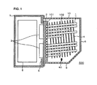
- FIG. 1 shows a vertical cross-sectional view of a cooling device according to an embodiment of the present invention
- Figure 2 shows a horizontal cross-sectional view
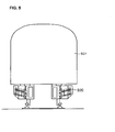
- Figure 5 shows a configuration when an electric conversion device according to the present embodiment is mounted on a railway car.
- An electric conversion device according to the present invention is provided, e.g., under the floor of a railway car and controls the rotational speed of an electric motor which drives the car by changing the frequency of power supplied to the electric motor.
- a power conversion device 500 is fixed to a car body 501 while the power conversion device 500 hangs down therefrom. Referring next to FIGS.
- a power semiconductor module 3 including devices such as IGBTs (Insulated Gate Bipolar Transistors) and FWDs (Free Wheel Diodes) is placed on one side of a heat receiving member 2 made of a metal (e.g., an aluminum alloy).
- the power semiconductor modules 3 constitute an inverter.
- the power semiconductor modules 3 are each fixed to the heat receiving member 2 via a member of grease (not shown) by a screw or the like (not shown).
- the heat receiving member 2 is fixed to a support member 5.
- a circuit component 8 e.g., an IGBT drive circuit
- a part of the power conversion device which includes the placed power semiconductor modules 3 is sealed in a case 7.
- Heat receiving portions 101 of U-shaped heat pipes 1 are embedded in the heat receiving member 2 on the side opposite to the side where the power semiconductor modules 3 are placed and are thermally connected to the heat receiving member 2 by soldering or the like.
- Heat dissipating portions 102 as two end parts of each U-shaped heat pipe 1 extend upward from the heat receiving member 2.
- the heat dissipating portions 102 include a plurality of fins 4.
- a cover 6 is provided on the heat pipe 1 side of the support member 5.
- the cover 6 includes openings 9 formed in a lower surface and openings 10 formed in an upper surface. Air taken in through the openings 9 at a lower part of the cover 6 flows upward by natural convection, as indicated by an arrow 40, and is discharged through the openings 10 at an upper part of the cover 6.
- Each heat pipe 1 is filled with coolant (e.g., pure water or hydrofluorocarbon).
- coolant e.g., pure water or hydrofluorocarbon
- the coolant heated by the heat receiving portion 101 evaporates into gas and moves to the heat dissipating portions 102.
- the coolant cooled at the heat dissipating portions 102 by air condenses back into liquid.
- the heat dissipating portions 102 are tilted at about 10°.
- the coolant condensed at the heat dissipating portions 102 returns to the heat receiving portion 101 by gravity. As described above, the coolant moves while repeating evaporation and condensation, which dissipates heat at the heat receiving member 2 into air.
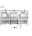
- FIG 3 shows the shapes and arrangement of the heat pipes at the heat receiving member 2.
- each heat pipe is arranged such that its longitudinal direction is substantially perpendicular to a direction indicated by the arrow 40 in which cooling air flows.
- the number of heat dissipating portions of the heat pipes 1 placed in two upper tiers of the heat receiving member 2 is 10 per tier.
- the number of heat dissipating portions of heat pipes 12 placed in five lower tiers of heat receiving member 2 is 6 per tier.
- the number of heat dissipating portions is smaller than at the upper part of the heat receiving member 2.
- the number of heat dissipating portions of heat pipes 11 at a middle part of the heat receiving member 2 is 8 per tier, which is intermediate between 10 and 6. That is, the heat pipes are arranged such that the number of heat dissipating portions of the heat pipes per unit area of the heat receiving member 2 is larger on the downstream side of cooling air than on the upstream side.
- the power semiconductor module 3 In cooling by natural convection, the temperature tends to be highest at and around the upper central power semiconductor module 3.
- the power semiconductor module 3 is located on the downstream side of a natural convection current where the temperature of air is high and is hard to dissipate heat to the left and to the right due to the left and right modules. A larger number of ones of the heat dissipating portions are concentrated at the module.
- the configuration is made so that cooling air from the upstream side directly hits the heat pipes on the downstream side. More specifically, the heat pipes are arranged such that the heat dissipating portions of the heat pipes in adjacent tiers, the numbers of which are different, do not overlap with each other when viewed from the inlet side of air (in the flow direction of cooling air).
- Straight heat pipes 13 for heat equalization without a portion which dissipates heat toward the fins 4 are further provided at the heat receiving member 2.
- the heat pipes 13 serve to equalize heat in a direction, transverse to the flow direction of cooling air of the heat receiving member 2, in which the heat receiving member 2 is likely to exhibit a wide range of temperature variation. This prevents the temperature of the heat receiving member 2 from being locally high at a central part.
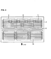
- Figure 4 shows another example of the arrangement of the heat pipes at the heat receiving member 2.
- the arrangement allows some overlap in a ventilation direction between the heat dissipating portions in adjacent tiers with the different numbers of heat pipes, and the U-shaped heat pipes 1 placed in the two upper tiers of the heat receiving member 2 are all set to the same length.
- the productivity is improved by reducing the number of kinds of U-shaped pipes, and the cooling performance can be expected to compare favorably with that of the structure in Figure 3 .
- the above-described structure allows minimization of a loss in pressure of air on the upstream side of cooling by natural convection and dissipation of a sufficient amount of heat on the downstream side. Accordingly, temperature rises at the heat receiving member 2 are more uniform, and a rise in temperature of the heat receiving member 2 and even a rise in temperature of the power semiconductor modules 3 can be reduced.
- the number of fins may be reduced on the upstream side and be increased on the downstream side, in addition to the adjustment of the number of heat pipes. Temperature rises at the heat receiving member 2 can be made more uniform by combining adjustment of the number of fins and adjustment of the number of heat pipes.
- Figure 6 shows a vertical cross-sectional view of a cooling device according to another embodiment of the present invention
- Figure 7 shows an arrangement of heat pipes at a heat receiving member 2 according to the present embodiment
- Figure 8 shows a configuration when an electric conversion device according to the present embodiment is mounted on a railway car.
- a power conversion device 1000 is fixed to a car body 501.
- An arrow 40 indicates a direction in which cooling air flows. Cooling air is taken in through a suction grill 51 by a blower 50 and is supplied to a cooling device 1001 of the power conversion device 1000.
- a power semiconductor module 3 including devices such as IGBTs and FWDs is placed on one side of the heat receiving member 2 (on the lower side in Figure 6 ).
- the power semiconductor modules 3 constitute an inverter.
- the power semiconductor modules 3 are each fixed to the heat receiving member 2 via a member of, e.g., grease (not shown) by a screw or the like (not shown).
- the heat receiving member 2 is fixed to a structural member 18 of a duct 19.
- An electronic component 8 e.g., an IGBT drive circuit
- a part of the power conversion device which includes the placed power semiconductor modules 3 is sealed in a case 7.
- Heat receiving portions 151 of U-shaped heat pipes 15 are embedded in the heat receiving member 2 on the side opposite to the side where the power semiconductor modules 3 are placed and are thermally connected to the heat receiving member 2 by soldering or the like.
- Heat dissipating portions 152 as two end parts of each U-shaped heat pipe 15 extend upward from the heat receiving member 2.
- a plurality of fins 4 made of metal (e.g., aluminum or copper) are connected to the heat dissipating portions 152 by press fitting or the like.
- the heat dissipating portions 152 and fins 4 are placed inside the duct 19.
- the duct 19 receives cooling air supplied by the blower.
- the arrow 40 indicates the direction of cooling air.
- each heat pipe is arranged such that its longitudinal direction is substantially parallel to the direction
- Heat pipes including heat receiving portions 161 and 171 shorter than the heat receiving portions 151 of the heat pipes 15 on the upstream side are used as heat pipes 16 and 17, respectively, on the downstream side such that the number of heat dissipating portions of the heat pipes, extending upward toward the fins, per unit area of the heat receiving member 2 is larger on the downstream side of cooling air than on the upstream side.
- the above-described structure allows minimization of a loss in pressure of air on the upstream side and dissipation of a sufficient amount of heat on the downstream side. Accordingly, temperature rises at the heat receiving member 2 are more uniform, and a rise in temperature of the heat receiving member 2 and even a rise in temperature of the power semiconductor modules 3 can be reduced.
- the temperature of a heat receiving member with attached power semiconductor devices can be made uniform, and a rise in temperature at the power semiconductor devices can be reduced. This allows reduction in size and weight of a cooling device.
- the number of fins may be reduced on the upstream side and be increased on the downstream side, in addition to the adjustment of the number of heat pipes.
- Temperature rises at the heat receiving member 2 can be made more uniform by combining adjustment of the number of fins and adjustment of the number of heat pipes.
Landscapes
- Engineering & Computer Science (AREA)
- Physics & Mathematics (AREA)
- Thermal Sciences (AREA)
- Microelectronics & Electronic Packaging (AREA)
- Life Sciences & Earth Sciences (AREA)
- Sustainable Development (AREA)
- Mechanical Engineering (AREA)
- General Engineering & Computer Science (AREA)
- Cooling Or The Like Of Semiconductors Or Solid State Devices (AREA)
- Cooling Or The Like Of Electrical Apparatus (AREA)
- Inverter Devices (AREA)
Applications Claiming Priority (1)
| Application Number | Priority Date | Filing Date | Title |
|---|---|---|---|
| JP2010289095A JP5560182B2 (ja) | 2010-12-27 | 2010-12-27 | 冷却装置およびそれを備えた電力変換装置 |
Publications (2)
| Publication Number | Publication Date |
|---|---|
| EP2469996A2 true EP2469996A2 (fr) | 2012-06-27 |
| EP2469996A3 EP2469996A3 (fr) | 2015-10-14 |
Family
ID=45440133
Family Applications (1)
| Application Number | Title | Priority Date | Filing Date |
|---|---|---|---|
| EP11192626.7A Withdrawn EP2469996A3 (fr) | 2010-12-27 | 2011-12-08 | Dispositif de refroidissement et dispositif de conversion de puissance l'incluant |
Country Status (4)
| Country | Link |
|---|---|
| EP (1) | EP2469996A3 (fr) |
| JP (1) | JP5560182B2 (fr) |
| KR (1) | KR101409102B1 (fr) |
| CN (1) | CN102569222B (fr) |
Cited By (18)
| Publication number | Priority date | Publication date | Assignee | Title |
|---|---|---|---|---|
| US20130155616A1 (en) * | 2011-12-16 | 2013-06-20 | Delta Electronics (Shanghai) Co., Ltd. | Hybrid heat sink and hybrid heat sink assembly for power module |
| FR3010274A1 (fr) * | 2013-08-27 | 2015-03-06 | Valeo Equip Electr Moteur | Bloc convertisseur de puissance de vehicule electrique ou hybride |
| EP2827691A3 (fr) * | 2013-07-16 | 2015-03-25 | LSIS Co., Ltd. | Armoire pour appareil électronique de puissance |
| EP2825011A3 (fr) * | 2013-07-10 | 2015-06-24 | Hitachi Ltd. | Convertisseur de traction et véhicule ferroviaire |
| GB2523625A (en) * | 2014-02-20 | 2015-09-02 | Hitachi Ltd | Power conversion device and railway vehicle equipped with the same |
| EP2940415A4 (fr) * | 2012-12-27 | 2016-11-02 | Furukawa Electric Co Ltd | Dispositif de refroidissement |
| EP3787387A1 (fr) * | 2019-08-29 | 2021-03-03 | Sungrow Power Supply Co., Ltd. | Onduleur et son dispositif de dissipation de chaleur |
| EP3680142A4 (fr) * | 2017-09-08 | 2021-06-16 | Hitachi, Ltd. | Dispositif de conversion d'énergie et voiture ferroviaire équipée du dispositif de conversion d'énergie |
| US20210215433A1 (en) * | 2018-05-30 | 2021-07-15 | Mitsubishi Electric Corporation | Cooling device |
| US11255608B2 (en) | 2018-08-06 | 2022-02-22 | Qorvo Us, Inc. | Heat exchanger assemblies for electronic devices |
| US11348850B2 (en) | 2017-03-27 | 2022-05-31 | Mitsubishi Electric Corporation | Vehicle power conversion device |
| US11387791B2 (en) | 2020-03-17 | 2022-07-12 | Qorvo Us, Inc. | Spatial power-combining devices with reduced size |
| US11431294B2 (en) | 2017-08-22 | 2022-08-30 | Qorvo Us, Inc. | Antenna waveguide transitions for solid state power amplifiers |
| US11564337B2 (en) * | 2020-03-17 | 2023-01-24 | Qorvo Us, Inc. | Thermal structures for heat transfer devices and spatial power-combining devices |
| US11621469B2 (en) | 2021-02-01 | 2023-04-04 | Qorvo Us, Inc. | Power-combining devices with increased output power |
| US11955687B2 (en) | 2022-01-10 | 2024-04-09 | Qorvo Us, Inc. | Structural arrangements for spatial power-combining devices |
| WO2024091980A1 (fr) * | 2022-10-24 | 2024-05-02 | Strategic Thermal Labs, Llc | Plaque froide à ailettes empilées dôtée d'une chambre à vapeur 3d |
| US12609434B2 (en) | 2022-03-14 | 2026-04-21 | Qorvo Us, Inc. | Antenna structures for spatial power-combining devices |
Families Citing this family (18)
| Publication number | Priority date | Publication date | Assignee | Title |
|---|---|---|---|---|
| CN103987607B (zh) * | 2011-12-09 | 2016-08-24 | 三菱电机株式会社 | 车辆用地板下装置的冷却装置 |
| JP5620032B1 (ja) * | 2012-12-11 | 2014-11-05 | 古河電気工業株式会社 | 冷却装置 |
| EP2933832A4 (fr) * | 2012-12-14 | 2016-09-21 | Furukawa Electric Co Ltd | Appareil de refroidissement |
| JP6182449B2 (ja) * | 2013-12-13 | 2017-08-16 | 昭和電工株式会社 | Led照明用放熱装置 |
| JP5950857B2 (ja) * | 2013-03-26 | 2016-07-13 | 豊田鉄工株式会社 | 自動車用電子回路の冷却装置 |
| JP6181436B2 (ja) * | 2013-06-20 | 2017-08-16 | 鉄建建設株式会社 | 打設コンクリートの養生方法およびコンクリート構造物 |
| JP2015050257A (ja) * | 2013-08-30 | 2015-03-16 | 株式会社東芝 | 車両用電力変換装置及び鉄道車両 |
| TWI619901B (zh) * | 2014-06-30 | 2018-04-01 | Hoya Candeo Optronics Corp | Light irradiation device |
| CN106231879A (zh) * | 2016-09-14 | 2016-12-14 | 绵阳富邦电控设备有限公司 | 一种易于散热的高频充电模块 |
| KR101922991B1 (ko) | 2016-12-23 | 2018-11-28 | 효성중공업 주식회사 | 전력변환장치용 전력소자 냉각장치 |
| DE112017007338T5 (de) * | 2017-03-31 | 2019-12-12 | Mitsubishi Electric Corporation | Kühleinrichtung und Fahrzeug-Leistungswandlereinrichtung |
| JP6758522B2 (ja) | 2017-11-08 | 2020-09-23 | 三菱電機株式会社 | 変圧器および電力変換装置 |
| JP7139656B2 (ja) * | 2018-03-30 | 2022-09-21 | 日本電産株式会社 | 冷却装置 |
| US11322422B2 (en) * | 2018-07-04 | 2022-05-03 | Mitsubishi Electric Corporation | Vehicle power conversion device |
| JP7079169B2 (ja) * | 2018-07-27 | 2022-06-01 | 古河電気工業株式会社 | 冷却装置 |
| CN114746711A (zh) * | 2019-12-09 | 2022-07-12 | 三菱电机株式会社 | 冷却装置及功率转换装置 |
| US11751361B2 (en) * | 2021-06-02 | 2023-09-05 | Microsoft Technology Licensing, Llc | Systems and methods for datacenter thermal management |
| KR200499883Y1 (ko) * | 2024-01-25 | 2025-12-24 | (주)솔리드메카 | 방열 성능을 조절할 수 있는 히트싱크 조립체 |
Citations (1)
| Publication number | Priority date | Publication date | Assignee | Title |
|---|---|---|---|---|
| JP2000161880A (ja) | 1998-11-26 | 2000-06-16 | Toshiba Corp | ヒートパイプ式冷却器 |
Family Cites Families (6)
| Publication number | Priority date | Publication date | Assignee | Title |
|---|---|---|---|---|
| JP2001024122A (ja) * | 1999-07-09 | 2001-01-26 | Mitsubishi Electric Corp | 発熱体の冷却装置 |
| JP2001251859A (ja) * | 2000-03-07 | 2001-09-14 | Toshiba Transport Eng Inc | 電力変換装置 |
| JP2004254387A (ja) * | 2003-02-19 | 2004-09-09 | Hitachi Ltd | 電力変換装置 |
| JP4948625B2 (ja) * | 2010-02-08 | 2012-06-06 | 古河電気工業株式会社 | 複数のフィンピッチを有する冷却装置 |
| JP5581119B2 (ja) * | 2010-06-07 | 2014-08-27 | 株式会社日立製作所 | 冷却装置,電力変換装置,鉄道車両 |
| EP2933832A4 (fr) * | 2012-12-14 | 2016-09-21 | Furukawa Electric Co Ltd | Appareil de refroidissement |
-
2010
- 2010-12-27 JP JP2010289095A patent/JP5560182B2/ja not_active Expired - Fee Related
-
2011
- 2011-12-08 EP EP11192626.7A patent/EP2469996A3/fr not_active Withdrawn
- 2011-12-21 CN CN201110432430.7A patent/CN102569222B/zh not_active Expired - Fee Related
- 2011-12-26 KR KR1020110142618A patent/KR101409102B1/ko not_active Expired - Fee Related
Patent Citations (1)
| Publication number | Priority date | Publication date | Assignee | Title |
|---|---|---|---|---|
| JP2000161880A (ja) | 1998-11-26 | 2000-06-16 | Toshiba Corp | ヒートパイプ式冷却器 |
Cited By (24)
| Publication number | Priority date | Publication date | Assignee | Title |
|---|---|---|---|---|
| US9136201B2 (en) * | 2011-12-16 | 2015-09-15 | Delta Electronics (Shanghai) Co., Ltd. | Hybrid heat sink and hybrid heat sink assembly for power module |
| US20130155616A1 (en) * | 2011-12-16 | 2013-06-20 | Delta Electronics (Shanghai) Co., Ltd. | Hybrid heat sink and hybrid heat sink assembly for power module |
| EP2940415A4 (fr) * | 2012-12-27 | 2016-11-02 | Furukawa Electric Co Ltd | Dispositif de refroidissement |
| EP2825011A3 (fr) * | 2013-07-10 | 2015-06-24 | Hitachi Ltd. | Convertisseur de traction et véhicule ferroviaire |
| EP2827691A3 (fr) * | 2013-07-16 | 2015-03-25 | LSIS Co., Ltd. | Armoire pour appareil électronique de puissance |
| EP2844052A3 (fr) * | 2013-08-27 | 2015-08-05 | Valeo Equipements Electriques Moteur | Bloc convertisseur de puissance de véhicule électrique ou hybride |
| FR3010274A1 (fr) * | 2013-08-27 | 2015-03-06 | Valeo Equip Electr Moteur | Bloc convertisseur de puissance de vehicule electrique ou hybride |
| GB2523625A (en) * | 2014-02-20 | 2015-09-02 | Hitachi Ltd | Power conversion device and railway vehicle equipped with the same |
| GB2523625B (en) * | 2014-02-20 | 2016-06-08 | Hitachi Ltd | Power conversion device and railway vehicle equipped with the same |
| US11348850B2 (en) | 2017-03-27 | 2022-05-31 | Mitsubishi Electric Corporation | Vehicle power conversion device |
| US11431294B2 (en) | 2017-08-22 | 2022-08-30 | Qorvo Us, Inc. | Antenna waveguide transitions for solid state power amplifiers |
| EP3680142A4 (fr) * | 2017-09-08 | 2021-06-16 | Hitachi, Ltd. | Dispositif de conversion d'énergie et voiture ferroviaire équipée du dispositif de conversion d'énergie |
| US20210215433A1 (en) * | 2018-05-30 | 2021-07-15 | Mitsubishi Electric Corporation | Cooling device |
| US11255608B2 (en) | 2018-08-06 | 2022-02-22 | Qorvo Us, Inc. | Heat exchanger assemblies for electronic devices |
| EP3787387A1 (fr) * | 2019-08-29 | 2021-03-03 | Sungrow Power Supply Co., Ltd. | Onduleur et son dispositif de dissipation de chaleur |
| US11387791B2 (en) | 2020-03-17 | 2022-07-12 | Qorvo Us, Inc. | Spatial power-combining devices with reduced size |
| US11564337B2 (en) * | 2020-03-17 | 2023-01-24 | Qorvo Us, Inc. | Thermal structures for heat transfer devices and spatial power-combining devices |
| US11665867B2 (en) | 2020-03-17 | 2023-05-30 | Qorvo Us, Inc. | Thermal structures for heat transfer devices and spatial power-combining devices |
| US12143074B2 (en) | 2020-03-17 | 2024-11-12 | Qorvo Us, Inc. | Spatial power-combining devices with reduced size |
| US11621469B2 (en) | 2021-02-01 | 2023-04-04 | Qorvo Us, Inc. | Power-combining devices with increased output power |
| US11955687B2 (en) | 2022-01-10 | 2024-04-09 | Qorvo Us, Inc. | Structural arrangements for spatial power-combining devices |
| US12525696B2 (en) | 2022-01-10 | 2026-01-13 | Qorvo Us, Inc. | Structural arrangements for spatial power-combining devices |
| US12609434B2 (en) | 2022-03-14 | 2026-04-21 | Qorvo Us, Inc. | Antenna structures for spatial power-combining devices |
| WO2024091980A1 (fr) * | 2022-10-24 | 2024-05-02 | Strategic Thermal Labs, Llc | Plaque froide à ailettes empilées dôtée d'une chambre à vapeur 3d |
Also Published As
| Publication number | Publication date |
|---|---|
| JP5560182B2 (ja) | 2014-07-23 |
| EP2469996A3 (fr) | 2015-10-14 |
| JP2012138439A (ja) | 2012-07-19 |
| KR101409102B1 (ko) | 2014-06-17 |
| KR20120074245A (ko) | 2012-07-05 |
| CN102569222B (zh) | 2014-11-05 |
| CN102569222A (zh) | 2012-07-11 |
Similar Documents
| Publication | Publication Date | Title |
|---|---|---|
| EP2469996A2 (fr) | Dispositif de refroidissement et dispositif de conversion de puissance l'incluant | |
| JP4929325B2 (ja) | 電力変換装置 | |
| JP5581119B2 (ja) | 冷却装置,電力変換装置,鉄道車両 | |
| TWI525300B (zh) | 功率模組用複合式散熱器組件 | |
| EP2996144B1 (fr) | Module semi-conducteur et véhicule à entraînement électrique | |
| CA2820330C (fr) | Systeme de refroidissement a deux phases pour composants electroniques | |
| US8081465B2 (en) | Cooling apparatus for semiconductor chips | |
| JP5872913B2 (ja) | 鉄道車両用電力変換装置の冷却器 | |
| CN103369932B (zh) | 一种功率器件散热器的散热片排布方法及散热器 | |
| JP2000092819A (ja) | 半導体冷却装置 | |
| WO2014106051A1 (fr) | Appareil et procédé de dissipation de chaleur pour module de dispositif de semi-conducteur de puissance | |
| JP6741561B2 (ja) | 鉄道車両の電力変換装置 | |
| EP2383779B1 (fr) | Base de montage | |
| JP5057838B2 (ja) | パワー半導体素子の冷却装置 | |
| JP5466073B2 (ja) | 電力変換装置および鉄道車両 | |
| JP2015156411A (ja) | 電力変換装置およびそれを搭載した鉄道車両 | |
| JP2017112151A (ja) | パワーユニットの冷却構造 | |
| JP6932632B2 (ja) | 液冷式冷却装置 | |
| JP6652467B2 (ja) | 電力変換装置および電力変換装置を搭載した鉄道車両 | |
| JP2020171196A (ja) | 鉄道車両の電力変換装置 | |
| JP3850319B2 (ja) | 車両用半導体冷却装置 | |
| JP2017069356A (ja) | 電力変換装置およびそれを搭載した鉄道車両 | |
| JP2016078654A (ja) | 電力変換装置およびそれを搭載した鉄道車両 | |
| JP2025116609A (ja) | 電力変換装置 | |
| CN203984847U (zh) | 光伏逆变器的自冷散热装置和自冷光伏逆变器 |
Legal Events
| Date | Code | Title | Description |
|---|---|---|---|
| 17P | Request for examination filed |
Effective date: 20111222 |
|
| AK | Designated contracting states |
Kind code of ref document: A2 Designated state(s): AL AT BE BG CH CY CZ DE DK EE ES FI FR GB GR HR HU IE IS IT LI LT LU LV MC MK MT NL NO PL PT RO RS SE SI SK SM TR |
|
| AX | Request for extension of the european patent |
Extension state: BA ME |
|
| PUAI | Public reference made under article 153(3) epc to a published international application that has entered the european phase |
Free format text: ORIGINAL CODE: 0009012 |
|
| PUAL | Search report despatched |
Free format text: ORIGINAL CODE: 0009013 |
|
| AK | Designated contracting states |
Kind code of ref document: A3 Designated state(s): AL AT BE BG CH CY CZ DE DK EE ES FI FR GB GR HR HU IE IS IT LI LT LU LV MC MK MT NL NO PL PT RO RS SE SI SK SM TR |
|
| AX | Request for extension of the european patent |
Extension state: BA ME |
|
| RIC1 | Information provided on ipc code assigned before grant |
Ipc: H05K 7/20 20060101AFI20150909BHEP |
|
| 17Q | First examination report despatched |
Effective date: 20170420 |
|
| GRAP | Despatch of communication of intention to grant a patent |
Free format text: ORIGINAL CODE: EPIDOSNIGR1 |
|
| INTG | Intention to grant announced |
Effective date: 20200110 |
|
| STAA | Information on the status of an ep patent application or granted ep patent |
Free format text: STATUS: THE APPLICATION HAS BEEN WITHDRAWN |
|
| 18W | Application withdrawn |
Effective date: 20200327 |