EP2470032B1 - Confectionneuse de bâtonnets-filtres - Google Patents
Confectionneuse de bâtonnets-filtres Download PDFInfo
- Publication number
- EP2470032B1 EP2470032B1 EP10752629.5A EP10752629A EP2470032B1 EP 2470032 B1 EP2470032 B1 EP 2470032B1 EP 10752629 A EP10752629 A EP 10752629A EP 2470032 B1 EP2470032 B1 EP 2470032B1
- Authority
- EP
- European Patent Office
- Prior art keywords
- tongue
- filter
- objects
- tow
- plug material
- Prior art date
- Legal status (The legal status is an assumption and is not a legal conclusion. Google has not performed a legal analysis and makes no representation as to the accuracy of the status listed.)
- Revoked
Links
Images








Classifications
-
- A—HUMAN NECESSITIES
- A24—TOBACCO; CIGARS; CIGARETTES; SIMULATED SMOKING DEVICES; SMOKERS' REQUISITES
- A24D—CIGARS; CIGARETTES; TOBACCO SMOKE FILTERS; MOUTHPIECES OF CIGARS OR CIGARETTES; MANUFACTURE OF TOBACCO SMOKE FILTERS OR MOUTHPIECES
- A24D3/00—Tobacco smoke filters, e.g. filter tips or filtering inserts; Filters specially adapted for simulated smoking devices; Mouthpieces of cigars or cigarettes
- A24D3/02—Manufacture of tobacco smoke filters
- A24D3/0204—Preliminary operations before the filter rod forming process, e.g. crimping, blooming
- A24D3/0212—Applying additives to filter materials
- A24D3/0216—Applying additives to filter materials the additive being in the form of capsules, beads or the like
-
- A—HUMAN NECESSITIES
- A24—TOBACCO; CIGARS; CIGARETTES; SIMULATED SMOKING DEVICES; SMOKERS' REQUISITES
- A24D—CIGARS; CIGARETTES; TOBACCO SMOKE FILTERS; MOUTHPIECES OF CIGARS OR CIGARETTES; MANUFACTURE OF TOBACCO SMOKE FILTERS OR MOUTHPIECES
- A24D3/00—Tobacco smoke filters, e.g. filter tips or filtering inserts; Filters specially adapted for simulated smoking devices; Mouthpieces of cigars or cigarettes
- A24D3/02—Manufacture of tobacco smoke filters
- A24D3/0204—Preliminary operations before the filter rod forming process, e.g. crimping, blooming
- A24D3/0208—Cutting filter materials
-
- A—HUMAN NECESSITIES
- A24—TOBACCO; CIGARS; CIGARETTES; SIMULATED SMOKING DEVICES; SMOKERS' REQUISITES
- A24D—CIGARS; CIGARETTES; TOBACCO SMOKE FILTERS; MOUTHPIECES OF CIGARS OR CIGARETTES; MANUFACTURE OF TOBACCO SMOKE FILTERS OR MOUTHPIECES
- A24D3/00—Tobacco smoke filters, e.g. filter tips or filtering inserts; Filters specially adapted for simulated smoking devices; Mouthpieces of cigars or cigarettes
- A24D3/06—Use of materials for tobacco smoke filters
- A24D3/061—Use of materials for tobacco smoke filters containing additives entrapped within capsules, sponge-like material or the like, for further release upon smoking
Definitions
- This invention relates to a machine for making filter rods for use in the manufacture of smoking articles such as filtered cigarettes.
- the machine is configured to insert objects into the filter rods.
- Filter rods used in the manufacture of filtered cigarettes conventionally comprise a plug of cellulose acetate tow wrapped with a paper plugwrap.
- Known filter rod making machines comprise a garniture which receives a flow of tow and a ribbon of filter paper and forms a paper wrapped elongate filter rod, which is subsequently cut into filter rod segments.
- the garniture usually has a tongue which compresses the filter tow as it passes therethrough.
- This type of filter making machine and in particular the garniture and tongue elements are well known per se to those skilled in the art.
- EP1833316 describes a machine configured to provide filter media, in particular granular material or pre-measured capsules, into filter material during filter rod manufacture.
- the machine of EP1833316 has a suction dome which sucks filter media into a plurality of spaced apart pockets formed in the circular face of a rotating pocket wheel. Rotation of the pocket wheel positions the pockets filled with filter media in register with the inlet of an air transport tube. Once aligned, vacuum is released and air pressure applied through a perforated pocket "bottom” to expel the media into the transport tube.
- the tube is arranged to enter the tongue of the machine so that when the filter media exits the discharge end of the tube it passes into the centre of the filter rod being formed. Subsequently, the rod is wrapped with paper.
- US-A-3844200 describes manufacture of a continuous filter rod having at spaced intervals pockets containing a selected additive in particulate or granular form with registry of the pockets being assured and migration of granules eliminated.
- the present invention provides an alternative approach to inserting objects into filter rod material during filter rod manufacture.
- the invention provides a machine for making filter rods for use in the manufacture of smoking articles, comprising a garniture configured to receive filter plug material and filter wrapping material and to form a wrapped elongate filter rod, the garniture comprising a tongue configured so that filter plug material is compressed as it passes therethrough; the filter maker further comprises a rotatable object-transport member arranged to receive objects from an object store and to deliver said objects directly into the tongue such that the objects are inserted into filter plug material passing through the tongue, and a cutter configured to cut the elongate filter rod, thereby forming filter rod segments having one or more objects therein.
- the filter plug material follows a steady, controlled path through the tongue and thereafter and thus the position and/or spacing of the objects in the eventual rod can be precisely controlled by placing the objects in appropriate positions of the filter plug material passing through the tongue.
- the filter plug material undergoes compression in the tongue such that the filter plug material presses against the objects so as to secure them in position in the filter plug material passing through the tongue. In this way, unwanted positional variation from object to object is minimised.
- the filter plug material is cellulose acetate tow.
- the objects are inserted into the tow in the tongue such that the objects in the wrapped elongate filter rod are evenly spaced. Further preferably, the objects are inserted into the tow in the tongue such that the one or more objects are axially centred within the eventual filter rods.
- the objects are preferably frangible fluid-containing capsules, but other objects such as pellets, strands, beads or any combination of pellets, strands, beads and capsules may alternatively or in addition be inserted.
- the capsule diameter is preferably within the range 2 - 6 mm.
- the rotatable object-transport member preferably penetrates into the tongue such that each object received by the rotatable object transfer member exits the object-transport member at an exit point inside the tongue.
- the rotatable object-transport member is preferably a rotatable wheel having a plurality of recesses arranged around the rim thereof
- the machine has a stuffer jet configured to compress the tow before it enters the garniture.
- the stuffer jet allows a more uniform density of tow to be achieved and enables manufacture of filters with different densities/pressure drops.
- the machine may have a first body part comprising a first tongue part and a second body part comprising the object-transport member and a second tongue part, and a hinge arranged so that the relative position of the first and second body parts can be adjusted between a first position in which the first and second tongue parts are separated so that the interior of the tongue is accessible for cleaning and tow threading and a second position in which the first and second tongue parts are aligned so that tow can pass from one to the other.
- FIGS 1 and 2 show part of a filter rod making machine 1.
- filter plug material in the form of cellulose acetate filter tow is drawn from a source, stretched in a set of stretching rollers (not shown) and compressed through stuffer jet 3 and through the tongue 4 of garniture 5.
- the machine 1 has a rotatable capsule transport wheel 6 arranged to deliver frangible flavourant-containing capsules from circumferential recesses 6a directly into the tongue so that the capsules come into contact with filter tow passing therethrough.
- the tow is paper wrapped in the garniture to form an elongate rod which is then cut to form filter rod segments, each of which contains a desired number of capsules, for example one, two, three or four.
- the filter rod segments can be subsequently used in cigarette manufacture to make cigarettes having one or more capsules in the cigarette filter.
- a filter rod segment containing two capsules is axially aligned with two paper wrapped tobacco rods positioned at opposing ends of the filter rod.
- a wrapper known as a tipping paper, is then wrapped around the tobacco rods and filter rod to join them together.
- the wrapped filter rod is then transversely cut through its centre, between the two capsules, thereby forming a pair of filtered cigarettes, each having a capsule in its filter.
- Each frangible capsule is preferably substantially spherical, formed from gelatin and contains a flavourant, for example menthol, spearmint, orange essence, mint, liquorice, eucalyptus, one or more of a variety of fruit flavours or any mixture of flavourants.
- a flavourant for example menthol, spearmint, orange essence, mint, liquorice, eucalyptus, one or more of a variety of fruit flavours or any mixture of flavourants.
- the transport wheel 6 is vertically orientated and rotatably mounted to the body 7 of the machine 1 on a shaft.
- the wheel 6 has a disk section 8 and a front section 9 bolted to the disk section 6.
- the disk section 8 is arranged between a capsule hopper 10 and the tongue 4 and is configured to sequentially transfer capsules therebetween.
- the tongue 4 of the garniture 5 is tapered along its length so as to radially compress the filter tow as it passes through the tongue 4. Tow compression in the tongue is the final tow compression stage of the rod making process.
- An opening is formed in the top of the tongue 4, the opening being wide enough to receive the disk section 8 of the transport wheel 6, which penetrates into the tongue 4 through the opening as shown in Figure 1 .
- capsules fall under gravity from the hopper 10 into the plurality of capsule-receiving recesses 6a arranged circumferentially around the rim of the disk section 8, as shown in Figure 1 .
- the clockwise rotating wheel 6 carries the capsules through the opening in the top of the tongue and into the tongue interior, where the capsules exit the wheel 6 and pass into the filter rod being formed.
- housing 7a is provided around the rim of disk section 8 to prevent capsules from falling from the wheel 6.
- the capsules are delivered directly into the tongue of the garniture, where the path of the tow is steady and controlled, remaining so until the rod is formed.
- the present machine allows the position of the capsules to be precisely controlled, with little variation from capsule to capsule or from filter to filter. This is desirable because consumers may perceive variations in capsule position negatively and may for example consider filters having off-centre capsules to be defective.
- the capsules are positioned in the tow so as to be axially aligned and centered within the eventual rod.
- the capsules exiting the wheel 6 may drop under gravity from the recesses 6a of the wheel 6 into the tow passing through the tongue 4.
- the transport wheel 6 may have a capsule ejection mechanism, for example an air-jet propulsion mechanism, configured to sequentially eject the capsules from the recesses in the rim section 8 and into the tow passing through the tongue 4.
- the transport wheel may alternatively, or in addition comprise a suction pump configured to apply suction to the capsules to hold them in position in the recesses before ejection.
- the machine 1 has a hinge mechanism which allows part of the tongue 4 to be lifted away from the machine 1. This facilitates threading of the tow from the stuffer jet 3 through the tongue 4 prior to machine start-up, and also allows convenient cleaning of the interior of the tongue 4.
- the hinge mechanism comprises a hinge 11 connected to upper body 12 and lower body 13 of the machine 1, and a lifting cylinder 14 passing through a bore 15 in the lower body and attached to the bottom of the distal end of the upper body 12.
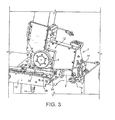
- the hinge 11 is arranged so that upper body 12 of machine 1 can pivot upwards with respect to lower body 13 from the operative position shown in Figure 2 to the lifted position shown in Figure 3 , and vice versa.
- the upper body 12 rests on the lower body 13 and the outlet of the stuffer jet 3 is in register with the tongue entrance 4 as shown in Figure 2 .
- an inlet portion 16 of the tongue is positioned clear of the stuffer jet so that an operator can access the tongue interior for convenient cleaning and tow threading.
- the machine can be selectively positioned in either position by raising or lowering the lifting cylinder 14, which is preferably hydraulically actuated.
- upper body 12 comprises hopper 10, transport wheel 6 and inlet tongue portion 16, which is shown in exploded perspective view.
- inlet tongue portion 16 comprises left and right sidewalls 17, 18, a plough 19 and a shoe 20.
- the plough 19 and shoe 20 are positioned at opposite ends of the inlet tongue portion 16 and between the sidewalls 17, 18, with a gap between the shoe 20 and plough 19.
- sidewalls 17 and 18 and plough 19 have extending upwardly attachment parts that have threaded holes in register with one another through which a set of bolts is threaded to hold the sidewalls 17, 18 and plough 19 together at one end of the inlet tongue portion 16.
- the shoe 20 is bolted between and to the sidewalls 17, 18 at the opposing end of the tongue portion 16.
- the sidewalls 17, 18 and plough 19 define an inlet tube 21 at the input end of the inlet tongue portion 16, through which tow enters the tongue 4, and an outlet 22 through which tow exits the inlet tongue portion 16.
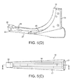
- Figure 5(b) which shows a bottom view
- the bottom of the inlet tongue portion 16 has an elongate opening 23 extending from the outlet 22 along the bottom of the inlet tongue portion 16 to the inlet tube 21.
- left and right sidewalls 17, 18 define an opening 24 in the top of inlet tongue portion 16 into which the wheel 6 penetrates, as shown in Figure 6 .
- the plough 19 and shoe 20 have arcuate surfaces 25, 26 facing the wheel 6 and arranged so that in operation, the wheel 6 rotates in close proximity to the surfaces 25 and 26.
- the surface 25 of the plough 19 prevents capsules from unintentionally falling from the clockwise rotating wheel 6 while the surface 26 of the shoe acts to scrape off any tow which becomes attached to the wheel 6 so as to present tow from being carried by the wheel out of the opening 24.
- a gap 27 is defined between the bottom end of surface 25 and the bottom end of surface 26, and the bottom end of surface 25 is lower than the bottom end of surface 26.
- stuffer jet 3 (which can also be referred to as a "transport jet") is mounted to the lower body 13 and is arranged to deliver tow directly into the inlet tube 21 of the tongue 4.
- the stuffer jet 3 allows a more uniform density of tow to be achieved in the eventual filters and enables filter manufacture with selected densities/pressure drops.
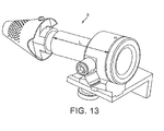
- the stuffer jet 3 is shown in more detail in Figure 13 .
- the length L of the body of the stuffer jet is preferably between 100 mm and 120 mm is further preferably 107.5 mm.
- lower body 13 has a garniture inlet channel 28 which tapers from the upstream to the downstream end thereof.
- the garniture tape runs along the floor of the channel 28 and a ribbon of plugwrap paper in frictional contact with the garniture tape is dragged through the channel 28 on top of the tape and is thereby drawn from a bobbin (not shown) along a series of rollers and into the garniture.
- the feature of a garniture tape in the garniture to progressively wrap plugwrap paper around the filter tow to form a filter rod is well known per se in the art and will not be described in detail herein.
- the inlet tongue portion 16 is adapted to fit into and cover the channel 28 in the operative position shown in Figure 2 .
- tow passes through the inlet tube 21 and onto the moving paper ribbon in the channel 28 via the elongate opening 23 in the bottom of the inlet tongue portion 16. The tow is then dragged along the channel 28 by frictional contact with the paper ribbon.
- tongue 4 further comprises a fixed tongue portion 29 positioned just downstream of the inlet tongue portion 16.
- tow in the channel 28 passes from through the outlet 22 of the inlet tongue portion 16 directly into the fixed tongue section 29.
- the inlet and fixed tongue sections 16, 29 are both tapered so that a continuous tapering is obtained along the length of the tongue 4 to compress the tow as it passes through.
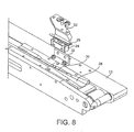
- the fixed tongue section 29 is shown in more detail in Figures 7 and 8 .
- the fixed tongue section 29 is formed as a tapered half-pipe, mounted in a tapered channel 30 formed in the lower body 13.
- channel 28 is integral with channel 30 and the inlet tongue portion 16 is aligned with the inlet of the fixed tongue section 29.
- mounting assembly 31 which comprises first, second and third mounting brackets 32, 33, 34.
- mounting bracket 32 is integrally formed with the top of tongue section 29 and bolted to mounting bracket 34.
- Mounting bracket 33 is bolted to mounting bracket 34 and to the lower body 13 of the machine 1, thereby fixing the fixed tongue section 29 in position.
- the plough 19 of tongue 4 is shown in more detail in Figure 9 .
- the plough 19 has an attachment part 35 and a tow separating edge 36 oppositely disposed to the arcuate surface 25.
- tow passing through the tongue 4 comes into contact with tow separating edge 36, which separates the tow into two tow streams on either side of the plough 19.
- a furrow is created in the tow, into which capsules are received from the wheel 6. This furrow extends beyond the length of the plough 19, up to a point where the movement of the tow flow causes the furrow to close.
- capsules are carried in the recesses 6a of wheel 6 through the opening 24 and to an exit point, where they exit the wheel and pass through the gap 27 between the plough and shoe and into furrow in the tow.
- the furrow subsequently closes around the capsules which are carried with the tow through the remainder of the garniture.
- the paper is subsequently fully wrapped around the tow by the action of the garniture to form an elongate paper wrapped rod, which is subsequently cut to form individual filter rods segments.
- FIG 10 illustrates different filter rods 37, 38, 39, which may be produced using the machine 1.
- each rod includes one or more evenly spaced gelatin capsules 40 surrounded by a plug of cellulose acetate tow 41, the tow being wrapped with a paper wrapper 42.
- the first, second and third rods 37, 38, 39 respectively comprise one, two and four capsules.
- the second rod 38 is twice as long as the first rod 37 and the third rod 39 is twice as long as the second rod 38.
- the skilled person will appreciate that many different rod configuration having different lengths and different numbers of capsules could be produced by the machine 1.
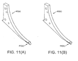
- Figure 11 (a) illustrates an alternative plough 43a to the plough 19 which has a capsule guide 44a arranged to receive capsules from the wheel 6 and to guide the capsules into the furrow.
- the capsule guide 44a assists in positioning the capsules so that once the rod is fully formed, the capsules are axially centred and axially aligned with one another.
- the capsule guide 44a is shaped so as to direct the capsules exiting the guide in a direction substantially parallel to the direction of movement of the tow. In this way, impact forces on the capsule are minimised, thus preventing capsule damage. Further, since the capsules do not have a substantial vertical velocity component, vertical deflection due to elastic interaction with the tow is minimised.
- Figure 11(b) illustrates a further alternative plough 43 (b) having an alternative capsule guide 44(b).
- the filter rods may be suitable for use in the manufacture of any smoking article, including cigarettes cigars and cigarillos whether based on tobacco, tobacco derivatives, expanded tobacco, reconstituted tobacco or tobacco substitutes and also heat-not-burn products.
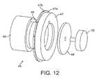
- Figure 12 shows an alternative transport wheel 45.
- transport wheel 45 has a front section 46, a delivery drum 47 and a clamp plate 48.
- a dowel pin 49 connects front section 46 to delivery drum 47.
- Clamp plate 48 is urged against delivery drum 47 by clamp screw 50, which is bolted to front section 46.
- the transport wheel 45 can be conveniently disassembled by removing clamp screw 50, thereby allowing easy cleaning of the components.
- the dowl pin 49 may be used as a marker to identify the angular position of the wheel 45 in relation to the shaft.
- an operator can record the rotational position so that the wheel can be loaded back onto the shaft in the same rotational position after cleaning.
- the hopper 10 may include a deflector or roller arranged to carry the weight of some of the capsules in the hopper, so that capsules do not become crushed therein.
- the hopper 10 may further comprise a vibrating plate to agitate the capsules, to facilitate transfer into the wheel 6.
- An air jet unit may be mounted in the hopper 10 to assist capsule movement.
- the wheel 6 may comprise raised notches to further agitate the capsules in the hopper.
- capsule-receiving recesses are preferably arranged evenly around the circumference of the wheel 6, 45 so that an even separation is achieved between capsules in the elongate filter rod, alternatively the capsule-receiving recesses may be arranged according to a different pattern to provide different spacings between different capsule pairs in the elongate filter rod.
- the capsule-receiving recesses 6a may be arranged so that the separation between a first pair of capsules is 24 mm while the separation between a neighbouring pair of capsules is 12 mm.
- a filter rod 51 produced by a machine having capsule-receiving recess arranged in this way is illustrated in Figure 10(d) .
- the separation between capsules in capsule pair 52 is 24 mm and the separation between capsules in neighbouring capsule pair 53 is 12 mm.
- the filter rod 51 is 108 mm long.
- the separation between the edge of the rod 51 and the first capsule is 6 mm.
Landscapes
- Chemical & Material Sciences (AREA)
- Engineering & Computer Science (AREA)
- Materials Engineering (AREA)
- Cigarettes, Filters, And Manufacturing Of Filters (AREA)
Claims (12)
- Confectionneuse de bâtonnets-filtres (1) destinée à être utilisée dans la fabrication d'articles à fumer comprenant :une garniture (5) configurée pour recevoir un matériau de bout-filtre et un matériau d'enveloppe de filtre et pour former un bâtonnet-filtre allongé enveloppé, la garniture (5) comprenant une languette (4) configurée de telle sorte que le matériau de bout-filtre soit compressé quand il passe par la languette ;un élément de transport d'objets rotatif (6) agencé pour délivrer des objets directement dans la languette (4) de telle sorte que les objets soient insérés dans le matériau de bout-filtre passant par la languette (4) ; etun couteau configuré pour couper le bâtonnet-filtre allongé, formant ainsi des segments de bâtonnet-filtre, chaque segment renfermant un ou plusieurs objets.
- Machine selon la revendication 1, dans laquelle l'élément de transport d'objets rotatif (6) pénètre dans la languette (4) de telle sorte que chaque objet sorte de l'élément de transport d'objets à un point de sortie à l'intérieur de la languette.
- Machine selon l'une quelconque des revendications précédentes, comprenant en outre un racleur (19) configuré pour ouvrir un sillon dans le matériau de bout-filtre passant par la languette, les objets étant insérés dans ledit sillon.
- Machine selon la revendication 3, dans laquelle le racleur comprend un élément de guidage (44a, 44b) agencé pour guider des objets depuis l'élément de transport d'objets rotatif jusque dans le sillon, et dans laquelle, éventuellement, l'élément de guidage est configuré pour guider les objets jusque dans le sillon dans un sens sensiblement parallèle au sens de déplacement du matériau de bout-filtre passant par la languette.
- Machine selon l'une quelconque des revendications précédentes, comprenant en outre un jet de remplissage (3) configuré pour compresser la mèche avant que la mèche entre dans la garniture.
- Machine selon l'une quelconque des revendications précédentes, ayant :une première partie de corps (13) comprenant une première partie de languette (29) ;une seconde partie de corps (12) comprenant ledit élément de transport d'objets (6) et une seconde partie de languette (16) ; etune articulation (11) agencée de telle sorte que la position relative des première et seconde parties de corps puisse être réglée entre une première position à laquelle les première et seconde parties de languette sont séparées de telle sorte que l'intérieur de la languette soit accessible en vue de son nettoyage et de l'enfilage de la mèche et une seconde position dans laquelle les première et seconde parties de languette sont alignées de telle sorte que la mèche puisse passer de l'une à l'autre.
- Machine selon la revendication 6, dans laquelle la seconde partie de corps (12) est une partie de corps supérieure et la première partie de corps est une partie de corps inférieure (13) et dans laquelle la partie de corps supérieure repose sur la partie de corps inférieure dans la seconde position.
- Machine selon la revendication 7, comprenant en outre un mécanisme de positionnement (14), configuré pour sélectivement lever et abaisser la partie de corps supérieure par rapport à la partie de corps inférieure, réglant ainsi la position relative des parties de corps supérieure et inférieure entre les première et seconde positions.
- Machine selon l'une quelconque des revendications précédentes, dans laquelle les objets sont des capsules frangibles renfermant un fluide.
- Procédé de confection de bâtonnets-filtres destiné à être utilisé dans la fabrication d'articles à fumer comprenant :la réception d'un matériau de bout-filtre et d'un matériau d'enveloppe de filtre ;l'entraînement du matériau de bout-filtre à travers la languette d'une garniture d'une confectionneuse de bâtonnets-filtres ;la compression du matériau de bout-filtre quand il passe à travers la languette de la garniture ;la délivrance d'objets depuis un élément de transport d'objets rotatif directement dans la languette de la garniture de telle sorte que les objets soient insérés dans le matériau de bout-filtre passant par la languette ;la formation d'un bâtonnet-filtre allongé enveloppé;la coupe du bâtonnet-filtre allongé en segments de bâtonnet-filtre, chaque segment renfermant un ou plusieurs objets.
- Procédé selon la revendication 10, comprenant en outre l'ouverture d'un sillon dans le matériau de bout-filtre passant par la languette, les objets étant insérés dans le sillon.
- Procédé selon la revendication 11, comprenant en outre le guidage des objets depuis l'élément de transport d'objets rotatif jusque dans le sillon, dans lequel, éventuellement, le guidage des objets comprend le guidage des objets jusque dans le sillon dans un sens sensiblement parallèle au sens de déplacement du matériau de bout-filtre passant par la languette.
Priority Applications (4)
| Application Number | Priority Date | Filing Date | Title |
|---|---|---|---|
| EP14198591.1A EP2888957B1 (fr) | 2009-08-28 | 2010-08-19 | Fabrication de tige de filtre |
| EP14198606.7A EP2896304A1 (fr) | 2009-08-28 | 2010-08-19 | Production de tige de filtre |
| EP19199800.4A EP3603424A1 (fr) | 2009-08-28 | 2010-08-19 | Fabricant de tige de filtre |
| PL10752629T PL2470032T3 (pl) | 2009-08-28 | 2010-08-19 | Urządzenie do wytwarzania pręta filtrującego |
Applications Claiming Priority (2)
| Application Number | Priority Date | Filing Date | Title |
|---|---|---|---|
| ZA2009/05994A ZA200905994B (en) | 2009-08-28 | 2009-08-28 | Filter rod maker |
| PCT/IB2010/053746 WO2011024105A1 (fr) | 2009-08-28 | 2010-08-19 | Confectionneuse de bâtonnets-filtres |
Related Child Applications (3)
| Application Number | Title | Priority Date | Filing Date |
|---|---|---|---|
| EP14198591.1A Division EP2888957B1 (fr) | 2009-08-28 | 2010-08-19 | Fabrication de tige de filtre |
| EP19199800.4A Division EP3603424A1 (fr) | 2009-08-28 | 2010-08-19 | Fabricant de tige de filtre |
| EP14198606.7A Division EP2896304A1 (fr) | 2009-08-28 | 2010-08-19 | Production de tige de filtre |
Publications (2)
| Publication Number | Publication Date |
|---|---|
| EP2470032A1 EP2470032A1 (fr) | 2012-07-04 |
| EP2470032B1 true EP2470032B1 (fr) | 2014-12-31 |
Family
ID=43500196
Family Applications (4)
| Application Number | Title | Priority Date | Filing Date |
|---|---|---|---|
| EP14198591.1A Active EP2888957B1 (fr) | 2009-08-28 | 2010-08-19 | Fabrication de tige de filtre |
| EP19199800.4A Withdrawn EP3603424A1 (fr) | 2009-08-28 | 2010-08-19 | Fabricant de tige de filtre |
| EP14198606.7A Withdrawn EP2896304A1 (fr) | 2009-08-28 | 2010-08-19 | Production de tige de filtre |
| EP10752629.5A Revoked EP2470032B1 (fr) | 2009-08-28 | 2010-08-19 | Confectionneuse de bâtonnets-filtres |
Family Applications Before (3)
| Application Number | Title | Priority Date | Filing Date |
|---|---|---|---|
| EP14198591.1A Active EP2888957B1 (fr) | 2009-08-28 | 2010-08-19 | Fabrication de tige de filtre |
| EP19199800.4A Withdrawn EP3603424A1 (fr) | 2009-08-28 | 2010-08-19 | Fabricant de tige de filtre |
| EP14198606.7A Withdrawn EP2896304A1 (fr) | 2009-08-28 | 2010-08-19 | Production de tige de filtre |
Country Status (17)
| Country | Link |
|---|---|
| US (1) | US20120220438A1 (fr) |
| EP (4) | EP2888957B1 (fr) |
| JP (2) | JP6129554B2 (fr) |
| KR (2) | KR102038485B1 (fr) |
| CN (1) | CN102573530B (fr) |
| AR (1) | AR079407A1 (fr) |
| AU (1) | AU2010288186A1 (fr) |
| BR (1) | BR112012004463A2 (fr) |
| CA (1) | CA2770912A1 (fr) |
| CL (1) | CL2012000486A1 (fr) |
| HU (1) | HUE046777T2 (fr) |
| MX (1) | MX2012002444A (fr) |
| MY (1) | MY163965A (fr) |
| PL (1) | PL2470032T3 (fr) |
| RU (1) | RU2560354C2 (fr) |
| WO (1) | WO2011024105A1 (fr) |
| ZA (1) | ZA200905994B (fr) |
Cited By (3)
| Publication number | Priority date | Publication date | Assignee | Title |
|---|---|---|---|---|
| EP2888957A1 (fr) | 2009-08-28 | 2015-07-01 | Tobacco Research And Development Institute (Proprietary) Limited | Fabrication de tige de filtre |
| EP3918929A1 (fr) | 2020-06-03 | 2021-12-08 | International Tobacco Machinery Poland SP. Z O.O. | Procédé et appareil de fabrication de tiges |
| EP4588373A1 (fr) | 2024-01-18 | 2025-07-23 | International Tobacco Machinery Poland Sp. z o.o. | Appareil de l'industrie du tabac pour la fabrication d'articles en forme de tige de l'industrie du tabac |
Families Citing this family (25)
| Publication number | Priority date | Publication date | Assignee | Title |
|---|---|---|---|---|
| ZA200901679B (en) | 2009-03-09 | 2015-08-26 | Tobacco Res And Development Institute (Pty) Ltd | Apparatus for introducing objects into filter rod material |
| ZA201008663B (en) | 2010-12-01 | 2014-08-27 | Tobacco Res And Dev Inst (Pty) Ltd | Feed mechanism |
| US9232820B2 (en) | 2011-03-25 | 2016-01-12 | Hauni Maschinenbau Ag | High speed object inserter and related methods |
| US9055768B2 (en) | 2011-03-25 | 2015-06-16 | Hauni Maschinenbau Ag | High speed object inserter and related methods |
| DE102011106718A1 (de) * | 2011-07-06 | 2013-01-10 | British American Tobacco (Germany) Gmbh | Flavoureinsatz zum Einlegen in eine Rauchartikel-Verpackung |
| DE102011085534B4 (de) * | 2011-11-01 | 2013-07-04 | Hauni Maschinenbau Ag | Verfahren und Vorrichtung zum Vereinzeln und Einlegen von Objekten in einen Materialstrang der Tabak verarbeitenden Industrie |
| DE202013012384U1 (de) * | 2012-03-05 | 2016-08-25 | Montrade S.R.L. | Vorrichtung zum Zuführen von Filtermaterial zu einer Filterstrangherstellungsmaschine |
| EP2636322B1 (fr) * | 2012-03-06 | 2018-05-23 | Hauni Maschinenbau GmbH | Dispositif pour l'introduction d'un ou plusieurs objets dans un composant de filtre d'un bâton de tabac et machine de l'industrie de traitement du tabac |
| PL223115B1 (pl) * | 2013-02-15 | 2016-10-31 | Int Tobacco Machinery Poland Spółka Z Ograniczoną Odpowiedzialnością | Sposób, mechanizm i urządzenie do chwilowego kompresowania materiału filtracyjnego |
| EP3850958B1 (fr) | 2015-09-29 | 2024-08-07 | British American Tobacco Mexico, S.A. De C.V. | Emballage de produits de l'industrie d'articles à fumer |
| WO2017093267A1 (fr) * | 2015-11-30 | 2017-06-08 | Philip Morris Products S.A. | Article à fumer comprenant un filtre à libération d'agent aromatisant améliorée |
| PL234036B1 (pl) * | 2016-09-06 | 2020-01-31 | Int Tobacco Machinery Poland Spolka Z Ograniczona Odpowiedzialnoscia | Zespół czyszczący, maszyna przemysłu tytoniowego do produkowania sztabek filtrowych wielosegmentowych i sposób czyszczenia ciągu elementów prętopodobnych |
| PL236586B1 (pl) * | 2016-11-19 | 2021-01-25 | Int Tobacco Machinery Poland Spolka Z Ograniczona Odpowiedzialnoscia | Urządzenie podające do podawania ciągłego materiału taśmowego do ciągłego pasma materiału włóknistego na maszynie do wytwarzania sztabek prętopodobnych przemysłu tytoniowego i maszyna do wytwarzania sztabek prętopodobnych |
| PL239186B1 (pl) * | 2017-03-10 | 2021-11-15 | Int Tabacco Machinery Poland Spolka Z Ograniczona Odpowiedzialnoscia | Urządzenie zasilające do podawania obiektów sferycznych dla przemysłu tytoniowego i sposób podawania obiektów sferycznych w maszynie przemysłu tytoniowego |
| HUE054649T2 (hu) * | 2017-05-18 | 2021-09-28 | Philip Morris Products Sa | Eljárás és berendezés aeroszol-fejlesztõ cikkhez rúdnak a kialakítására egy anyaglapból |
| IT201800006810A1 (it) * | 2018-06-29 | 2019-12-29 | Unità di ricezione e trattamento per capsule contenenti un preparato di base per un prodotto di gelateria. | |
| EP3613298A1 (fr) * | 2018-08-21 | 2020-02-26 | Philip Morris Products S.A. | Canal de compression et procédé de compression d'un corps de matériau |
| DE102019107387A1 (de) * | 2019-03-22 | 2020-09-24 | Hauni Maschinenbau Gmbh | Vorrichtung zum Herstellen eines Filterstrangs der Tabak verarbeitenden Industrie |
| KR20210035534A (ko) | 2019-09-24 | 2021-04-01 | 한스텍주식회사 | 항산화 유효물질인 프로폴리스를 가용화한 화장품용 조성물, 화장품 및 제조방법 |
| PL3918928T3 (pl) | 2020-06-03 | 2023-05-08 | International Tobacco Machinery Poland Sp. Z O.O. | Sposób i urządzenie do wytwarzania sztabek |
| EP3944774B1 (fr) * | 2020-07-29 | 2025-07-02 | International Tobacco Machinery Poland Sp. z o.o. | Unité d'alimentation pour distribuer des billes et appareil de fabrication de tiges |
| GB202019408D0 (en) * | 2020-12-09 | 2021-01-20 | Essentra Filter Products Dev Co Pte Ltd | Method and apparatus for making a filter element |
| KR102591099B1 (ko) | 2021-03-31 | 2023-10-18 | 한스텍주식회사 | 천연 성분을 이용한 보습과 항산화 기능을 갖는 화장품 제조방법 |
| IT202200025431A1 (it) | 2022-12-13 | 2024-06-13 | Gd Spa | Macchina per l'inserimento di componenti discreti in un cordone continuo dell'industria del tabacco |
| EP4417068B1 (fr) * | 2023-02-15 | 2025-04-02 | International Tobacco Machinery Poland Sp. z o.o. | Appareil de pliage pour plier un boudin de matériau de remplissage placé dans une tige continue de l'industrie du tabac |
Family Cites Families (21)
| Publication number | Priority date | Publication date | Assignee | Title |
|---|---|---|---|---|
| GB709198A (en) * | 1950-07-06 | 1954-05-19 | Desmond Walter Molins | Improvements in or relating to a method of and apparatus for making mouthpiece cigarettes |
| GB1106931A (en) * | 1963-10-04 | 1968-03-20 | Molins Organization Ltd | Improvements in apparatus for producing composite filter plugs |
| US3345917A (en) * | 1964-12-28 | 1967-10-10 | Eastman Kodak Co | Machine and method for controlling the circumference of paper wrapped cigarette filter rods |
| US3844200A (en) | 1973-05-07 | 1974-10-29 | Brown & Williamson Tobacco Corp | Continuous manufacture of a multiple filter rod having spaced pockets containing particulate material |
| GB1457510A (en) * | 1973-07-09 | 1976-12-01 | British American Tobacco Co | Production of tobacco smoke filter rod |
| US3884741A (en) * | 1974-02-22 | 1975-05-20 | Brown & Williamson Tobacco Corp | Method and apparatus for the manufacture of filter rods containing particulate material by a split rod technique |
| US3943832A (en) * | 1974-03-13 | 1976-03-16 | Brown & Williamson Tobacco Corporation | Method and apparatus for the handling of tow in the manufacture of tobacco smoke filters containing particulate material |
| US4016830A (en) * | 1975-07-16 | 1977-04-12 | Brown & Williamson Tobacco Corporation | Apparatus for dispensing spaced deposits of particulate material |
| GB1585761A (en) * | 1977-06-01 | 1981-03-11 | Cigarette Components Ltd | Tobacco smoke filters |
| US4862905A (en) * | 1987-06-15 | 1989-09-05 | R. J. Reynolds Tobacco Company | Rods containing pelletized material |
| US5331976A (en) * | 1992-10-21 | 1994-07-26 | Hoechst Celanese Corporation | Transport jet adapter |
| US7115085B2 (en) * | 2003-09-12 | 2006-10-03 | R.J. Reynolds Tobacco Company | Method and apparatus for incorporating objects into cigarette filters |
| US7381175B2 (en) * | 2004-12-22 | 2008-06-03 | Philip Morris Usa Inc. | Compound filter rod making apparatus and process |
| US8938671B2 (en) * | 2005-12-16 | 2015-01-20 | The 41St Parameter, Inc. | Methods and apparatus for securely displaying digital images |
| US7849889B2 (en) * | 2006-05-31 | 2010-12-14 | Philip Morris Usa Inc. | Applicator wheel for filling cavities with metered amounts of particulate material |
| US7740019B2 (en) * | 2006-08-02 | 2010-06-22 | R.J. Reynolds Tobacco Company, Inc. | Equipment and associated method for insertion of material into cigarette filters |
| CN1907154B (zh) * | 2006-08-03 | 2010-08-18 | 川渝中烟工业公司 | 一种使香料线稳定居中于滤嘴中心的装置 |
| ITBO20060751A1 (it) * | 2006-10-31 | 2007-01-30 | Gd Spa | Macchina confezionatrice di filtri per articoli da fumo |
| US7972254B2 (en) * | 2007-06-11 | 2011-07-05 | R.J. Reynolds Tobacco Company | Apparatus for inserting objects into a filter component of a smoking article, and associated method |
| US8381947B2 (en) * | 2007-12-05 | 2013-02-26 | Philip Morris Usa Inc. | Bead feeder |
| ZA200905994B (en) | 2009-08-28 | 2014-05-28 | Tobacco Res And Dev Inst (Pty) Ltd | Filter rod maker |
-
2009
- 2009-08-28 ZA ZA2009/05994A patent/ZA200905994B/en unknown
-
2010
- 2010-08-19 KR KR1020177030080A patent/KR102038485B1/ko not_active Expired - Fee Related
- 2010-08-19 CN CN201080038271.6A patent/CN102573530B/zh not_active Expired - Fee Related
- 2010-08-19 KR KR1020127008040A patent/KR20120058586A/ko not_active Ceased
- 2010-08-19 US US13/393,209 patent/US20120220438A1/en not_active Abandoned
- 2010-08-19 AU AU2010288186A patent/AU2010288186A1/en not_active Abandoned
- 2010-08-19 EP EP14198591.1A patent/EP2888957B1/fr active Active
- 2010-08-19 EP EP19199800.4A patent/EP3603424A1/fr not_active Withdrawn
- 2010-08-19 PL PL10752629T patent/PL2470032T3/pl unknown
- 2010-08-19 EP EP14198606.7A patent/EP2896304A1/fr not_active Withdrawn
- 2010-08-19 MY MYPI2012000744A patent/MY163965A/en unknown
- 2010-08-19 EP EP10752629.5A patent/EP2470032B1/fr not_active Revoked
- 2010-08-19 MX MX2012002444A patent/MX2012002444A/es not_active Application Discontinuation
- 2010-08-19 BR BR112012004463A patent/BR112012004463A2/pt not_active Application Discontinuation
- 2010-08-19 WO PCT/IB2010/053746 patent/WO2011024105A1/fr not_active Ceased
- 2010-08-19 HU HUE14198591A patent/HUE046777T2/hu unknown
- 2010-08-19 JP JP2012526158A patent/JP6129554B2/ja active Active
- 2010-08-19 RU RU2012111975/12A patent/RU2560354C2/ru active
- 2010-08-19 CA CA2770912A patent/CA2770912A1/fr not_active Abandoned
- 2010-08-27 AR ARP100103136A patent/AR079407A1/es not_active Application Discontinuation
-
2012
- 2012-02-24 CL CL2012000486A patent/CL2012000486A1/es unknown
-
2015
- 2015-12-28 JP JP2015255812A patent/JP6523947B2/ja not_active Expired - Fee Related
Cited By (4)
| Publication number | Priority date | Publication date | Assignee | Title |
|---|---|---|---|---|
| EP2888957A1 (fr) | 2009-08-28 | 2015-07-01 | Tobacco Research And Development Institute (Proprietary) Limited | Fabrication de tige de filtre |
| EP3918929A1 (fr) | 2020-06-03 | 2021-12-08 | International Tobacco Machinery Poland SP. Z O.O. | Procédé et appareil de fabrication de tiges |
| EP4588373A1 (fr) | 2024-01-18 | 2025-07-23 | International Tobacco Machinery Poland Sp. z o.o. | Appareil de l'industrie du tabac pour la fabrication d'articles en forme de tige de l'industrie du tabac |
| WO2025153727A1 (fr) | 2024-01-18 | 2025-07-24 | International Tobacco Machinery Poland Sp. Z O.O. | Appareil de l'industrie du tabac pour la production de tiges de l'industrie du tabac |
Also Published As
| Publication number | Publication date |
|---|---|
| WO2011024105A1 (fr) | 2011-03-03 |
| ZA200905994B (en) | 2014-05-28 |
| RU2560354C2 (ru) | 2015-08-20 |
| KR20170120197A (ko) | 2017-10-30 |
| MY163965A (en) | 2017-11-15 |
| BR112012004463A2 (pt) | 2016-04-05 |
| EP2888957A1 (fr) | 2015-07-01 |
| CN102573530A (zh) | 2012-07-11 |
| EP3603424A1 (fr) | 2020-02-05 |
| EP2888957B1 (fr) | 2019-10-02 |
| HK1172800A1 (en) | 2013-05-03 |
| KR102038485B1 (ko) | 2019-10-30 |
| CA2770912A1 (fr) | 2011-03-03 |
| EP2470032A1 (fr) | 2012-07-04 |
| JP6523947B2 (ja) | 2019-06-05 |
| CL2012000486A1 (es) | 2012-08-10 |
| AR079407A1 (es) | 2012-01-25 |
| KR20120058586A (ko) | 2012-06-07 |
| JP2016073310A (ja) | 2016-05-12 |
| HUE046777T2 (hu) | 2020-03-30 |
| JP6129554B2 (ja) | 2017-05-17 |
| PL2470032T3 (pl) | 2015-07-31 |
| MX2012002444A (es) | 2012-05-08 |
| CN102573530B (zh) | 2014-09-24 |
| RU2012111975A (ru) | 2013-10-10 |
| JP2013502919A (ja) | 2013-01-31 |
| EP2896304A1 (fr) | 2015-07-22 |
| US20120220438A1 (en) | 2012-08-30 |
| AU2010288186A1 (en) | 2012-03-01 |
Similar Documents
| Publication | Publication Date | Title |
|---|---|---|
| EP2888957B1 (fr) | Fabrication de tige de filtre | |
| KR101916920B1 (ko) | 공급 메커니즘 | |
| US9028385B2 (en) | Equipment for insertion of objects into smoking articles | |
| US4862905A (en) | Rods containing pelletized material | |
| KR20070088639A (ko) | 복합필터로드 제조장치와 제조방법 | |
| WO2013017624A1 (fr) | Élément filtrant qui incorpore une capsule qui peut être rompue, procédé de fabrication d'une cigarette comprenant un élément filtrant qui incorpore une capsule qui peut être rompue, et appareil permettant de fabriquer la cigarette comprenant un élément filtrant qui incorpore une capsule qui peut être rompue | |
| US11134713B2 (en) | Method and apparatus for producing micro bead bearing filter rod | |
| HK1172800B (en) | Filter rod maker | |
| EP4011221A1 (fr) | Procédé et appareil de fabrication d'un élément de filtre |
Legal Events
| Date | Code | Title | Description |
|---|---|---|---|
| PUAI | Public reference made under article 153(3) epc to a published international application that has entered the european phase |
Free format text: ORIGINAL CODE: 0009012 |
|
| 17P | Request for examination filed |
Effective date: 20120229 |
|
| AK | Designated contracting states |
Kind code of ref document: A1 Designated state(s): AL AT BE BG CH CY CZ DE DK EE ES FI FR GB GR HR HU IE IS IT LI LT LU LV MC MK MT NL NO PL PT RO SE SI SK SM TR |
|
| DAX | Request for extension of the european patent (deleted) | ||
| 17Q | First examination report despatched |
Effective date: 20131218 |
|
| GRAP | Despatch of communication of intention to grant a patent |
Free format text: ORIGINAL CODE: EPIDOSNIGR1 |
|
| INTG | Intention to grant announced |
Effective date: 20140718 |
|
| GRAS | Grant fee paid |
Free format text: ORIGINAL CODE: EPIDOSNIGR3 |
|
| GRAA | (expected) grant |
Free format text: ORIGINAL CODE: 0009210 |
|
| AK | Designated contracting states |
Kind code of ref document: B1 Designated state(s): AL AT BE BG CH CY CZ DE DK EE ES FI FR GB GR HR HU IE IS IT LI LT LU LV MC MK MT NL NO PL PT RO SE SI SK SM TR |
|
| REG | Reference to a national code |
Ref country code: CH Ref legal event code: EP Ref country code: GB Ref legal event code: FG4D |
|
| REG | Reference to a national code |
Ref country code: IE Ref legal event code: FG4D |
|
| REG | Reference to a national code |
Ref country code: AT Ref legal event code: REF Ref document number: 703820 Country of ref document: AT Kind code of ref document: T Effective date: 20150215 |
|
| REG | Reference to a national code |
Ref country code: DE Ref legal event code: R096 Ref document number: 602010021445 Country of ref document: DE Effective date: 20150219 |
|
| REG | Reference to a national code |
Ref country code: NL Ref legal event code: T3 |
|
| REG | Reference to a national code |
Ref country code: NL Ref legal event code: T3 |
|
| PG25 | Lapsed in a contracting state [announced via postgrant information from national office to epo] |
Ref country code: NO Free format text: LAPSE BECAUSE OF FAILURE TO SUBMIT A TRANSLATION OF THE DESCRIPTION OR TO PAY THE FEE WITHIN THE PRESCRIBED TIME-LIMIT Effective date: 20150331 Ref country code: LT Free format text: LAPSE BECAUSE OF FAILURE TO SUBMIT A TRANSLATION OF THE DESCRIPTION OR TO PAY THE FEE WITHIN THE PRESCRIBED TIME-LIMIT Effective date: 20141231 Ref country code: FI Free format text: LAPSE BECAUSE OF FAILURE TO SUBMIT A TRANSLATION OF THE DESCRIPTION OR TO PAY THE FEE WITHIN THE PRESCRIBED TIME-LIMIT Effective date: 20141231 |
|
| REG | Reference to a national code |
Ref country code: NL Ref legal event code: T3 |
|
| REG | Reference to a national code |
Ref country code: LT Ref legal event code: MG4D |
|
| PG25 | Lapsed in a contracting state [announced via postgrant information from national office to epo] |
Ref country code: SE Free format text: LAPSE BECAUSE OF FAILURE TO SUBMIT A TRANSLATION OF THE DESCRIPTION OR TO PAY THE FEE WITHIN THE PRESCRIBED TIME-LIMIT Effective date: 20141231 Ref country code: HR Free format text: LAPSE BECAUSE OF FAILURE TO SUBMIT A TRANSLATION OF THE DESCRIPTION OR TO PAY THE FEE WITHIN THE PRESCRIBED TIME-LIMIT Effective date: 20141231 Ref country code: LV Free format text: LAPSE BECAUSE OF FAILURE TO SUBMIT A TRANSLATION OF THE DESCRIPTION OR TO PAY THE FEE WITHIN THE PRESCRIBED TIME-LIMIT Effective date: 20141231 Ref country code: GR Free format text: LAPSE BECAUSE OF FAILURE TO SUBMIT A TRANSLATION OF THE DESCRIPTION OR TO PAY THE FEE WITHIN THE PRESCRIBED TIME-LIMIT Effective date: 20150401 |
|
| REG | Reference to a national code |
Ref country code: AT Ref legal event code: MK05 Ref document number: 703820 Country of ref document: AT Kind code of ref document: T Effective date: 20141231 |
|
| REG | Reference to a national code |
Ref country code: HU Ref legal event code: AG4A Ref document number: E023705 Country of ref document: HU |
|
| PG25 | Lapsed in a contracting state [announced via postgrant information from national office to epo] |
Ref country code: SK Free format text: LAPSE BECAUSE OF FAILURE TO SUBMIT A TRANSLATION OF THE DESCRIPTION OR TO PAY THE FEE WITHIN THE PRESCRIBED TIME-LIMIT Effective date: 20141231 Ref country code: RO Free format text: LAPSE BECAUSE OF FAILURE TO SUBMIT A TRANSLATION OF THE DESCRIPTION OR TO PAY THE FEE WITHIN THE PRESCRIBED TIME-LIMIT Effective date: 20141231 Ref country code: ES Free format text: LAPSE BECAUSE OF FAILURE TO SUBMIT A TRANSLATION OF THE DESCRIPTION OR TO PAY THE FEE WITHIN THE PRESCRIBED TIME-LIMIT Effective date: 20141231 Ref country code: CZ Free format text: LAPSE BECAUSE OF FAILURE TO SUBMIT A TRANSLATION OF THE DESCRIPTION OR TO PAY THE FEE WITHIN THE PRESCRIBED TIME-LIMIT Effective date: 20141231 |
|
| REG | Reference to a national code |
Ref country code: PL Ref legal event code: T3 |
|
| REG | Reference to a national code |
Ref country code: FR Ref legal event code: PLFP Year of fee payment: 6 |
|
| PG25 | Lapsed in a contracting state [announced via postgrant information from national office to epo] |
Ref country code: AT Free format text: LAPSE BECAUSE OF FAILURE TO SUBMIT A TRANSLATION OF THE DESCRIPTION OR TO PAY THE FEE WITHIN THE PRESCRIBED TIME-LIMIT Effective date: 20141231 Ref country code: IS Free format text: LAPSE BECAUSE OF FAILURE TO SUBMIT A TRANSLATION OF THE DESCRIPTION OR TO PAY THE FEE WITHIN THE PRESCRIBED TIME-LIMIT Effective date: 20150430 |
|
| REG | Reference to a national code |
Ref country code: DE Ref legal event code: R026 Ref document number: 602010021445 Country of ref document: DE |
|
| PLBI | Opposition filed |
Free format text: ORIGINAL CODE: 0009260 |
|
| PG25 | Lapsed in a contracting state [announced via postgrant information from national office to epo] |
Ref country code: EE Free format text: LAPSE BECAUSE OF FAILURE TO SUBMIT A TRANSLATION OF THE DESCRIPTION OR TO PAY THE FEE WITHIN THE PRESCRIBED TIME-LIMIT Effective date: 20141231 Ref country code: DK Free format text: LAPSE BECAUSE OF FAILURE TO SUBMIT A TRANSLATION OF THE DESCRIPTION OR TO PAY THE FEE WITHIN THE PRESCRIBED TIME-LIMIT Effective date: 20141231 |
|
| PLAF | Information modified related to communication of a notice of opposition and request to file observations + time limit |
Free format text: ORIGINAL CODE: EPIDOSCOBS2 |
|
| PLAX | Notice of opposition and request to file observation + time limit sent |
Free format text: ORIGINAL CODE: EPIDOSNOBS2 |
|
| 26 | Opposition filed |
Opponent name: HAUNI MASCHINENBAU AG Effective date: 20150929 |
|
| PG25 | Lapsed in a contracting state [announced via postgrant information from national office to epo] |
Ref country code: SI Free format text: LAPSE BECAUSE OF FAILURE TO SUBMIT A TRANSLATION OF THE DESCRIPTION OR TO PAY THE FEE WITHIN THE PRESCRIBED TIME-LIMIT Effective date: 20141231 |
|
| PLAF | Information modified related to communication of a notice of opposition and request to file observations + time limit |
Free format text: ORIGINAL CODE: EPIDOSCOBS2 |
|
| PG25 | Lapsed in a contracting state [announced via postgrant information from national office to epo] |
Ref country code: MC Free format text: LAPSE BECAUSE OF FAILURE TO SUBMIT A TRANSLATION OF THE DESCRIPTION OR TO PAY THE FEE WITHIN THE PRESCRIBED TIME-LIMIT Effective date: 20141231 Ref country code: LU Free format text: LAPSE BECAUSE OF FAILURE TO SUBMIT A TRANSLATION OF THE DESCRIPTION OR TO PAY THE FEE WITHIN THE PRESCRIBED TIME-LIMIT Effective date: 20150819 |
|
| REG | Reference to a national code |
Ref country code: CH Ref legal event code: PL |
|
| PG25 | Lapsed in a contracting state [announced via postgrant information from national office to epo] |
Ref country code: CH Free format text: LAPSE BECAUSE OF NON-PAYMENT OF DUE FEES Effective date: 20150831 Ref country code: LI Free format text: LAPSE BECAUSE OF NON-PAYMENT OF DUE FEES Effective date: 20150831 |
|
| PLBB | Reply of patent proprietor to notice(s) of opposition received |
Free format text: ORIGINAL CODE: EPIDOSNOBS3 |
|
| PG25 | Lapsed in a contracting state [announced via postgrant information from national office to epo] |
Ref country code: BE Free format text: LAPSE BECAUSE OF FAILURE TO SUBMIT A TRANSLATION OF THE DESCRIPTION OR TO PAY THE FEE WITHIN THE PRESCRIBED TIME-LIMIT Effective date: 20141231 |
|
| REG | Reference to a national code |
Ref country code: IE Ref legal event code: MM4A |
|
| PG25 | Lapsed in a contracting state [announced via postgrant information from national office to epo] |
Ref country code: IE Free format text: LAPSE BECAUSE OF NON-PAYMENT OF DUE FEES Effective date: 20150819 |
|
| PLAB | Opposition data, opponent's data or that of the opponent's representative modified |
Free format text: ORIGINAL CODE: 0009299OPPO |
|
| REG | Reference to a national code |
Ref country code: FR Ref legal event code: PLFP Year of fee payment: 7 |
|
| R26 | Opposition filed (corrected) |
Opponent name: HAUNI MASCHINENBAU GMBH Effective date: 20150929 |
|
| PG25 | Lapsed in a contracting state [announced via postgrant information from national office to epo] |
Ref country code: MT Free format text: LAPSE BECAUSE OF FAILURE TO SUBMIT A TRANSLATION OF THE DESCRIPTION OR TO PAY THE FEE WITHIN THE PRESCRIBED TIME-LIMIT Effective date: 20141231 |
|
| PG25 | Lapsed in a contracting state [announced via postgrant information from national office to epo] |
Ref country code: SM Free format text: LAPSE BECAUSE OF FAILURE TO SUBMIT A TRANSLATION OF THE DESCRIPTION OR TO PAY THE FEE WITHIN THE PRESCRIBED TIME-LIMIT Effective date: 20141231 |
|
| PG25 | Lapsed in a contracting state [announced via postgrant information from national office to epo] |
Ref country code: CY Free format text: LAPSE BECAUSE OF FAILURE TO SUBMIT A TRANSLATION OF THE DESCRIPTION OR TO PAY THE FEE WITHIN THE PRESCRIBED TIME-LIMIT Effective date: 20141231 |
|
| REG | Reference to a national code |
Ref country code: FR Ref legal event code: PLFP Year of fee payment: 8 |
|
| PGFP | Annual fee paid to national office [announced via postgrant information from national office to epo] |
Ref country code: NL Payment date: 20170821 Year of fee payment: 8 |
|
| PGFP | Annual fee paid to national office [announced via postgrant information from national office to epo] |
Ref country code: IT Payment date: 20170823 Year of fee payment: 8 Ref country code: FR Payment date: 20170822 Year of fee payment: 8 Ref country code: DE Payment date: 20170822 Year of fee payment: 8 Ref country code: GB Payment date: 20170822 Year of fee payment: 8 |
|
| REG | Reference to a national code |
Ref country code: DE Ref legal event code: R064 Ref document number: 602010021445 Country of ref document: DE Ref country code: DE Ref legal event code: R103 Ref document number: 602010021445 Country of ref document: DE |
|
| PGFP | Annual fee paid to national office [announced via postgrant information from national office to epo] |
Ref country code: PL Payment date: 20170808 Year of fee payment: 8 Ref country code: BG Payment date: 20170823 Year of fee payment: 8 |
|
| RDAF | Communication despatched that patent is revoked |
Free format text: ORIGINAL CODE: EPIDOSNREV1 |
|
| STAA | Information on the status of an ep patent application or granted ep patent |
Free format text: STATUS: THE PATENT HAS BEEN GRANTED |
|
| RDAG | Patent revoked |
Free format text: ORIGINAL CODE: 0009271 |
|
| STAA | Information on the status of an ep patent application or granted ep patent |
Free format text: STATUS: PATENT REVOKED |
|
| 27W | Patent revoked |
Effective date: 20171120 |
|
| GBPR | Gb: patent revoked under art. 102 of the ep convention designating the uk as contracting state |
Effective date: 20171120 |
|
| PG25 | Lapsed in a contracting state [announced via postgrant information from national office to epo] |
Ref country code: MK Free format text: LAPSE BECAUSE OF FAILURE TO SUBMIT A TRANSLATION OF THE DESCRIPTION OR TO PAY THE FEE WITHIN THE PRESCRIBED TIME-LIMIT Effective date: 20141231 |
|
| PG25 | Lapsed in a contracting state [announced via postgrant information from national office to epo] |
Ref country code: PT Free format text: LAPSE BECAUSE OF FAILURE TO SUBMIT A TRANSLATION OF THE DESCRIPTION OR TO PAY THE FEE WITHIN THE PRESCRIBED TIME-LIMIT Effective date: 20141231 |
|
| PG25 | Lapsed in a contracting state [announced via postgrant information from national office to epo] |
Ref country code: AL Free format text: LAPSE BECAUSE OF FAILURE TO SUBMIT A TRANSLATION OF THE DESCRIPTION OR TO PAY THE FEE WITHIN THE PRESCRIBED TIME-LIMIT Effective date: 20141231 |
|
| PGFP | Annual fee paid to national office [announced via postgrant information from national office to epo] |
Ref country code: HU Payment date: 20180815 Year of fee payment: 9 Ref country code: TR Payment date: 20180809 Year of fee payment: 9 |