EP2470074B1 - Estimation de forme d'instrument - Google Patents
Estimation de forme d'instrument Download PDFInfo
- Publication number
- EP2470074B1 EP2470074B1 EP10841432.7A EP10841432A EP2470074B1 EP 2470074 B1 EP2470074 B1 EP 2470074B1 EP 10841432 A EP10841432 A EP 10841432A EP 2470074 B1 EP2470074 B1 EP 2470074B1
- Authority
- EP
- European Patent Office
- Prior art keywords
- location
- tool
- shape
- mps
- sensor
- Prior art date
- Legal status (The legal status is an assumption and is not a legal conclusion. Google has not performed a legal analysis and makes no representation as to the accuracy of the status listed.)
- Active
Links
Images



Classifications
-
- A—HUMAN NECESSITIES
- A61—MEDICAL OR VETERINARY SCIENCE; HYGIENE
- A61B—DIAGNOSIS; SURGERY; IDENTIFICATION
- A61B5/00—Measuring for diagnostic purposes; Identification of persons
- A61B5/06—Devices, other than using radiation, for detecting or locating foreign bodies ; Determining position of diagnostic devices within or on the body of the patient
-
- A—HUMAN NECESSITIES
- A61—MEDICAL OR VETERINARY SCIENCE; HYGIENE
- A61B—DIAGNOSIS; SURGERY; IDENTIFICATION
- A61B5/00—Measuring for diagnostic purposes; Identification of persons
- A61B5/06—Devices, other than using radiation, for detecting or locating foreign bodies ; Determining position of diagnostic devices within or on the body of the patient
- A61B5/065—Determining position of the probe employing exclusively positioning means located on or in the probe, e.g. using position sensors arranged on the probe
- A61B5/066—Superposing sensor position on an image of the patient, e.g. obtained by ultrasound or x-ray imaging
-
- A—HUMAN NECESSITIES
- A61—MEDICAL OR VETERINARY SCIENCE; HYGIENE
- A61B—DIAGNOSIS; SURGERY; IDENTIFICATION
- A61B8/00—Diagnosis using ultrasonic, sonic or infrasonic waves
- A61B8/08—Clinical applications
- A61B8/0833—Clinical applications involving detecting or locating foreign bodies or organic structures
-
- A—HUMAN NECESSITIES
- A61—MEDICAL OR VETERINARY SCIENCE; HYGIENE
- A61B—DIAGNOSIS; SURGERY; IDENTIFICATION
- A61B8/00—Diagnosis using ultrasonic, sonic or infrasonic waves
- A61B8/52—Devices using data or image processing specially adapted for diagnosis using ultrasonic, sonic or infrasonic waves
- A61B8/5215—Devices using data or image processing specially adapted for diagnosis using ultrasonic, sonic or infrasonic waves involving processing of medical diagnostic data
- A61B8/5238—Devices using data or image processing specially adapted for diagnosis using ultrasonic, sonic or infrasonic waves involving processing of medical diagnostic data for combining image data of patient, e.g. merging several images from different acquisition modes into one image
-
- A—HUMAN NECESSITIES
- A61—MEDICAL OR VETERINARY SCIENCE; HYGIENE
- A61B—DIAGNOSIS; SURGERY; IDENTIFICATION
- A61B34/00—Computer-aided surgery; Manipulators or robots specially adapted for use in surgery
- A61B34/20—Surgical navigation systems; Devices for tracking or guiding surgical instruments, e.g. for frameless stereotaxis
-
- A—HUMAN NECESSITIES
- A61—MEDICAL OR VETERINARY SCIENCE; HYGIENE
- A61B—DIAGNOSIS; SURGERY; IDENTIFICATION
- A61B5/00—Measuring for diagnostic purposes; Identification of persons
- A61B5/72—Signal processing specially adapted for physiological signals or for diagnostic purposes
- A61B5/7271—Specific aspects of physiological measurement analysis
- A61B5/7285—Specific aspects of physiological measurement analysis for synchronizing or triggering a physiological measurement or image acquisition with a physiological event or waveform, e.g. an ECG signal
- A61B5/7289—Retrospective gating, i.e. associating measured signals or images with a physiological event after the actual measurement or image acquisition, e.g. by simultaneously recording an additional physiological signal during the measurement or image acquisition
Definitions
- the instant invention relates generally to medical imaging and more particularly to a system for tool shape estimation.
- a medical tool e.g., a catheter
- a clinician using the tool may require specific knowledge of the shape of the tool within the region of interest.
- Conventional approaches for determining the shape typically involve extensive use of fluoroscopy (i.e., a manual determination of the shape of the tool). It would be desirable to reduce or eliminate the use of fluoroscopy in order to reduce patient exposure to x-rays.
- An approach taken in the art for estimating tool shape involves providing a system for detecting (during use) the location of a position sensor embedded in a catheter and then rendering the catheter tip based on the detected sensor location, as seen by reference to U.S. Patent No. 6,233,476 entitled MEDICAL POSITIONING SYSTEM to Strommer et al.
- Strommer et al. disclose rendering a representation of the tool on a display based only on the location reading from the sensor.
- EP 1 862 114 A1 relates to sensing the position of an object placed within a living body, in particular, to detection and compensation of artifacts experienced during position sensing of a probe in a living body, wherein there is no control unit determining a reconstruction representing the shape of a tool using at least a positional constraint. Further, no position of a valve entrance in a heart of a patient using electrodes as they pass by the valve entrance during insertion of a catheter is used.
- One advantage of the apparatus and methods described, depicted and claimed herein relates to the ability to accurately determine the shape of a medical tool (e.g., a catheter) within a region of interest in a patient's body (or cavity thereof) with only a reduced ( i.e ., minimal) use of supplemental imaging such as fluoroscopy.
- a medical tool e.g., a catheter
- supplemental imaging such as fluoroscopy
- the medical tool preferably includes a location sensor disposed therein or affixed thereto (e.g., at the distal end or tip).
- the apparatus includes a localization system (e.g., a medical positioning system (MPS)) configured to output a location reading indicative of the sensor's location in a reference coordinate system.
- MPS medical positioning system
- a control unit is configured to produce a reconstruction representing the tool's shape as a function of (1) one or more positional constraints, which may include a first location in the coordinate system defined by a point along a tool path where the patient's body anatomically constrains free movement of the tool in at least one degree of freedom and (2) a shape constraint corresponding to a relaxation shape of the tool.
- the positional constraint may be further defined by a second location indicative of the tool's current location (e.g., the tool's location at a time the reconstruction is performed).
- the first location may be obtained by capturing an MPS location reading when the tool is observed ( e.g., by a user according to an x-ray image of the region of interest) to be constrained by the body.
- a superimposing processor is configured to superimpose the reconstruction of the tool's shape on an image of the region of interest that was acquired at an earlier time.
- the control unit also determines the location of the tool shape reconstruction in the reference coordinate system ( i.e ., the MPS coordinate system).
- the control unit is configured to use a further location reading obtained from another location sensor disposed at a different point in the tool ( e.g., a mid-tool location).
- the relaxation shape of the tool may be determined in accordance with a model (e.g., defined by a polynomial expression) or may alternatively be determined during use in accordance with an alternate embodiment described below.
- the relaxation shape of the tool may be determined during use.
- the tool includes a guidewire disposed within a lumen formed in the tool (e.g., catheter) extending between proximal and distal ends.
- the guidewire has a location sensor, for example, at its distal end.
- the control unit then records a plurality of location readings in accordance with the output of the guidewire's location sensor while the guidewire is advanced or withdrawn through the catheter ( i.e., relative movement between the stable catheter and the moving guidewire so as to accurately record the catheter's shape).
- the control unit is configured to then determine the tool's relaxation shape based on the recorded location readings.
- the use of fluoroscopy in determining the shape of a medical tool can be reduced thereby also reducing the patient's exposure to x-rays.
- Figure 1 is a diagrammatic view of a system 10 in which aspects of a medical tool shape reconstruction or estimation system may be embodied. It should be understood that while embodiments will be described in connection with a magnetic field-based positioning system in a catheter-lab environment, this is exemplary only and not limiting in nature.
- the system 10 as depicted includes a main control unit 12 (e.g., a processor) having various input/output mechanisms 14, a display 16, an optional image database 18, a localization system such as a medical positioning system (MPS) 20, an electrocardiogram (ECG) monitor 22, one or more MPS location sensors respectively designated 24 1 , 24 2 and 24 3 , and an MPS-enabled medical device or tool 26 which itself includes one and optionally more MPS location sensors, shown in exemplary fashion as having two such sensors 24 1 and 24 2 .
- a main control unit 12 e.g., a processor
- various input/output mechanisms 14 e.g., a display 16
- an optional image database 18 e.g., a localization system
- MPS medical positioning system
- ECG electrocardiogram
- the control unit 12 is programmed to perform a plurality of functions, including a tool shape reconstruction or estimation function performed by a tool shape reconstruction or estimation block 28.
- the estimation block 28 is configured to produce a reconstruction of the tool's shape as a function of (1) inputs from a shape constraint input block 30 1 , which inputs may include a relaxation shape of the tool and (2) inputs from a positional constraints input block 30 2 , which inputs may include not only the tool's current location from one or more tool location sensors but may also include one or more locations corresponding to points along the tool path where the patient's body anatomically constrains the free movement of the tool in at least one degree of freedom.
- the positional constraints may also include locations of other anatomically constricting landmarks and the like.
- the estimation block 28 may also determine the location in a reference coordinate system of the tool shape reconstruction.
- the reference coordinate system may be the coordinate system of MPS 20.
- the tool shape reconstruction may be used for a number of purposes, such as being superimposed (graphically) on an image of the region of interest ( e.g., acquired at an earlier time).
- the resulting composite image may then be displayed to a user on the display 16.
- the user may use the composite image for navigation purposes during a medical procedure.
- the control unit 12 is further configured to include a superimposing processor 32.
- the input/output mechanisms 14 may comprise conventional apparatus for interfacing with a computer-based control unit, for example, a keyboard, a mouse, a tablet, a foot pedal, a switch or the like.
- the display 16 may also comprise conventional apparatus.
- Embodiments consistent with the invention may find use in navigation applications that use imaging of a region of interest (as described above). Therefore the system 10 may include the image database 18.
- the image database 18 may be configured to store image information relating to the patient's body, for example a region of interest surrounding a destination site for the medical tool and/or multiple regions of interest along a navigation path contemplated to be traversed by the medical tool to reach the destination site.
- the image data in the database 18 may comprise known image types including (1) one or more two-dimensional still images acquired at respective, individual times in the past; (2) a plurality of related two-dimensional images obtained in real-time from an image acquisition device (e.g., fluoroscopic images from an x-ray imaging apparatus, such as that shown in exemplary fashion in Figure 2 ) wherein the image database acts as a buffer (live fluoroscopy); and/or (3) a sequence of related two-dimensional images defining a cine-loop (CL) wherein each image in the sequence has at least an ECG timing parameter associated therewith adequate to allow playback of the sequence in accordance with acquired real-time ECG signals obtained from the ECG monitor 22.
- an image acquisition device e.g., fluoroscopic images from an x-ray imaging apparatus, such as that shown in exemplary fashion in Figure 2
- the image database acts as a buffer (live fluoroscopy)
- a sequence of related two-dimensional images defining a cine-loop (CL) wherein each image in the sequence has
- the image database may also include three-dimensional image data as well.
- the images may be acquired through any imaging modality, now known or hereafter developed, for example X-ray, ultra-sound, computerized tomography, nuclear magnetic resonance or the like.
- the location readings may each include at least one or both of a position and an orientation (P&O) relative to a reference coordinate system, which may be the coordinate system of the MPS 20.
- the P&O may be expressed as a position (i.e., a coordinate in three axes X, Y and Z) and orientation ( i.e., an azimuth and elevation) of the magnetic field sensor in the magnetic field relative to a magnetic field generator(s) or transmitter(s).
- the MPS 20 determines respective locations (i.e ., P&O) in the reference coordinate system based on capturing and processing signals received from the magnetic field sensors 24 i while such sensors are disposed in a controlled low-strength AC magnetic field (see Fig. 2 ).
- Each sensor may comprise one or more magnetic field detection coil(s), and it should be understood that variations as to the number of coils, their geometries, spatial relationships, the existence or absence of cores and the like are possible. From an electromagnetic perspective, these sensors develop a voltage that is induced on the coil residing in a changing magnetic field, as contemplated here.
- the sensors 24 i are thus configured to detect one or more characteristics of the magnetic field(s) in which they are disposed and generate an indicative signal, which is further processed by the MPS 20 to obtain a respective P&O thereof.
- a sensor see U.S. Patent No. 7,197,354 entitled SYSTEM FOR DETERMINING THE POSITION AND ORIENTATION OF A CATHETER issued to Sobe.
- the first MPS location sensor 24 1 and optionally (in certain embodiments) the second MPS location sensor 24 2 are associated with the MPS-enabled medical tool 26.
- the third MPS sensor namely, the patient reference sensor (PRS) 24 3 (if provided in the system 10) is configured to provide a stable, positional reference of the patient's body so as to allow motion compensation for gross patient body movements and/or respiration-induced movements.
- the PRS 24 3 may be attached to the patient's manubrium sternum, a stable place on the chest, or other location that is relatively positionally stable.
- the PRS 24 3 is also configured to detect one or more characteristics of the magnetic field in which it is disposed wherein the MPS 20 provides a location reading (e.g., a position and orientation (P&O) reading) indicative of the PRS's three-dimensional position and orientation in the reference coordinate system.
- a location reading e.g., a position and orientation (P&O) reading
- the electro-cardiogram (ECG) monitor 22 is configured to continuously detect an electrical timing signal of the heart organ through the use of a plurality of ECG electrodes (not shown), which may be externally-affixed to the outside of a patient's body.
- the timing signal generally corresponds to the particular phase of the cardiac cycle, among other things.
- the ECG signal(s) may be used by the control unit 12 for ECG synchronized play-back of a previously captured sequences of images (cine loop) stored in the database 18.
- the ECG monitor 22 and ECG-electrodes may both comprise conventional components.
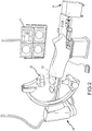
- FIG. 2 is a diagrammatic view of the system 10 as incorporated into a larger system that has self-contained imaging capability. It should be understood that while the medical tool shape estimation approach described herein, in certain embodiments, does not require extensive use of fluoroscopy, other aspects of any medical procedure may involve such use, at least intermittently.
- the system 10 is shown as being incorporated into an fluoroscopic imaging system 34, which may include commercially available fluoroscopic imaging components (i.e., "Catheter Lab”).
- MTA magnetic transmitter assembly
- P&O position and orientation
- the MTA 36 is configured to generate the magnetic field(s) in and around the patient's chest cavity, in a predefined three-dimensional space identified as a motion box 40.
- the processing core 38 is responsive to these detected signals and is configured to calculate respective three-dimensional position and orientation (P&O) readings for each MPS sensor 24 i in the motion box 40.
- P&O three-dimensional position and orientation
- the positional relationship between the image coordinate system and the MPS reference coordinate system may be calculated based on a known optical-magnetic calibration of the system (e.g., established during setup), since the positioning system and imaging system may be considered fixed relative to each other in such an embodiment.
- a registration step registering the MPS coordinate system and the image coordinate system may need to be performed so that MPS location readings can be properly coordinated with any particular image being used.
- an MPS 20 will be described in greater detail below in connection with Figure 7 .
- Figure 3 is a diagrammatic view of a medical tool being inserted in a region of interest in a patient's body.
- the disclosed method and apparatus overcomes the disadvantages of the prior art by providing a method for reconstructing the curve representing the shape of a tool (e.g., a catheter), fitted with an MPS sensor, during minimal invasive procedures with minimal use of fluoroscopy.
- a tool shape reconstruction is determined using positional constraints and constraints relating to the shape of the tool.
- the medical tool takes the form of a catheter 26 having an MPS location sensor 24 1 at a distal end.
- the catheter 26 may be maneuvered by a physician towards a desired region of interest 42 (e.g., the right atrium of the heart) contained within the patient's body, which maneuvering involves passing the catheter 26 through an insertion region 44 ( i.e., in this example where the destination site is the right atrium, the Superior Vena Cava (SVC) is the insertion region).
- SVC Superior Vena Cava
- the region proximate the SVC 44 anatomically constrains that portion of the catheter 26 that passes through the SVC 44. Accordingly, one positional constraint, in this example, is the location of the SVC 44, which is designated as location 46.
- the location of the SVC 44 in the coordinate system may be recorded using the MPS sensor 24 1 when the catheter 26 passes through the SVC 44. Alternatively, another MPS location sensor (not shown) may be used. Either way, the recorded location defines a so-called positional constraint on the tool shape reconstruction.
- positional constraint is the location defined by a point along the tool path where the patient's body anatomically constrains the free movement of the tool in at least one degree of freedom (e.g., location 46).
- This type of positional constraint exists in this example where the catheter 26 is being inserted through the SVC 44. It should be understood that depending on the medical procedure, the medical tool involved, the range of tool movement contemplated as well other considerations, many other locations may qualify as a constricting type positional constraint. It should be further understood that a degree of freedom may correspond to any one or more of the axes or orientation angles in the reference coordinate system.
- the SVC 44 constrains the range of lateral movement of the catheter but not axial (up/down) movement of the catheter. This is true at the moment the catheter is first inserted through the SVC 44 and remains true even at later time as advancement of the catheter proceeds into the right atrium.
- An additional type of positional constraint may be the location of the MPS sensor 24 1 at the tip of the catheter 26 at a time when the tool shape reconstruction is calculated (i.e., the current tool location).
- An example of this type of positional constraint is shown as location 48. This positional constraint is relevant to the tool shape reconstruction at the current time. What ties the relevancy of the earlier recorded location ( i.e ., location 46) to the current tool shape reconstruction is the anatomical constraint imposed by the patient's body on the subsequent motion of the tool. It should be understood that the path of the tool's tip ( i.e., where the location sensor is embedded in the illustrative embodiment) does not necessarily resemble its current shape.
- the control unit 12 is configured to determine the location 46 through interaction with a user.
- the user may visually detect (e.g., according to an inspection of an x-ray image of the region of interest 42) when the catheter 26 passes through the SVC 44, and more particularly when a part of the catheter (e.g., the tip) passes through the SVC 44 ( i.e., the anatomically constraining location in the body).
- the control unit 12 may superimpose a representation of the catheter tip's location on the x-ray image being displayed, for example, in the form of cross-hairs or the like, to facilitate user recognition of when the tool is in the desired location to record an MPS location reading.
- the control unit 12 includes a user interface (e.g., a graphical user interface (GUI)) configured to receive an input signal from the user to record the MPS location reading when this condition has been detected visually.
- the signal may take the form of some user-initiated action such as actuation of a joystick, a push button, a pointing device ( e.g., mouse, stylus and digital tablet, track-ball, touch pad) or by any other conventional means.
- the user interface of the control unit 12 recognizes the user request and the control unit 12 then records the MPS location reading corresponding to the location 46 ( i.e ., as detected by the MPS sensor 24 1 ).
- the estimation block 28 is configured to utilize other external inputs, such as the location of a landmark representing an anatomical constriction on tool movement.
- a constrictive landmark is similar to what has been described above for location 46.
- the control unit 12 may provide a mechanism for defining such a landmark (virtual landmark), which may in turn be used by the estimation block 28 to compute the tool shape reconstruction.
- One approach for defining a virtual landmark may be as seen by reference to U.S. Patent Publication 2006/0058647 , Application No. 11/233,420 entitled "METHOD AND SYSTEM FOR DELIVERING A MEDICAL DEVICE TO A SELECTED POSITION WITHIN A LUMEN", to Strommer.
- the control unit 12 may be configured to employ the general steps of (i) placing a MPS-enabled device at the desired landmark, by means of visualization on either live or pre-recorded image; and (ii) using a graphical user interface (GUI) or other control to designate the landmark at the location of the tip of the MPS-enabled device.
- the estimation block 28 may use the location (P&O) of the constrictive landmark in the tool shape estimation.
- the estimation block 28 uses the locations 46, 48 in conjunction with at least one further location, such as the location 50 obtained through the use of at least one further MPS location sensor (not shown) mounted on the catheter 26 at a point intermediate its distal and proximal ends.
- the locations 46, 48, 50 collectively define a set of positional constraints used by the estimation block 28 in determining the catheter's current shape.
- the estimation block 28 also receives a shape constraint as an input (input block 30 1 ) for use in its processing logic to reconstruct the tool's current shape.
- the shape constraint corresponds to the tool's relaxation shape.
- the relaxation shape is predetermined and defined by a model stored in memory (not shown) accessible to the estimation block 28.
- the model may reflect a mathematical description of the curve (e.g., in the form of a polynomial expression) that corresponds to the relaxation shape of the catheter 26.
- a, b and c are coefficients (i.e., this assumes a second order polynomial-of course, higher order polynomial expressions are possible as are other models employing different mathematical descriptions).
- the relaxation shape may be described in three-dimensions as well and that the above-description referenced to a 2D mathematical description is exemplary only and not limiting in nature.
- the model may alternatively be configured to accommodate non-fixed shape tools, such as, for example, a steerable catheter.
- the model may be configured to require the input of additional pieces of information, such as the location(s) of one or more restricting landmark(s) in close proximity to the tool tip and/or one or more location(s) from one or more additional MPS location sensors fitted to the non-fixed shape tool.
- the model may in addition receive mechanical characteristics of the tool as an input. These characteristics may be expressed as position-dependent functions of mechanical admittance to force, i.e ., for each point along the tool, what geometrical displacement from the relaxation shape will result from exerting a force unit. This function may be expressed as a series of step-wise functions or as higher dimension polynomials expressing continuous functions of force admittance as functions of the location along the tool.
- Figure 4 is a diagrammatic view of a curve (i.e ., the tool shape reconstruction) produced by the estimation block 28 representing the shape of the medical tool, such as the catheter 26 in Figure 3 .
- the reconstruction 52 in the depiction, may be, for example, a spline representation of the curve.
- a spline is a functional representation of a curve. Any curve may be approximated by a function or a set of functions.
- the reconstruction 52 may include one or more functions in order to fully describe the curve.
- the estimation block 28 produces the reconstruction 52 by processing the input information from the shape constraint input block 30 1 and the positional constraints input block 30 2 and converging upon a solution consistent with the positional and shape constraints.
- One way of computing the optimal tool shape given the constraints is to perform an iterative search of a global minimum over a cost function associated with the relaxation shape of the tool.
- An example of a straight-forward cost function is the symmetric area between the current iteration's computed shape and the relaxation shape of the tool. The iteration step will try to reduce the value of the cost function in the next iteration by moving a part of the next iteration's computed shape closer to the relaxation shape.
- the constraints to be met in this computation may have different priorities: the portion (or portions) of the tool where MPS sensors are equipped can hardly be altered, as the position and orientation of the sensor is very accurate; whereas the relation between the portion (or portions) of the tool and other constraints, like landmarks, may not be as rigid ( i.e., such landmarks do not necessarily indicate the exact location through which the tool currently passes). Moreover, while a sensor position and orientation is rigidly tied to a specific point along the tool (e.g., the tool's tip), it is not known exactly which part of the tool resides at a constraint like a landmark. The algorithm uses this prioritization of constraints to iteratively search for a minimum cost function value.
- the reconstruction 52 produced by the estimation block 28 represents the current shape of the tool.
- the reconstruction of the tool's shape must be located in the reference coordinate system (i.e., the MPS coordinate system). This may be achieved by the control unit 12 through the use of one of MPS location readings indicative of the tool's current location obtained from MPS 20 in conjunction with the tool shape reconstruction.
- the control unit 12 may determine the location after the shape determination or as a unitary process with the tool shape calculation.
- the image coordinate system must be registered with the reference coordinate system (described above).
- the display of the tool for example, as a 3D object projected onto a previously-acquired image enables the operator to perform the clinical routine (i.e ., navigation) without using live fluoroscopy.
- cannulation of the coronary sinus (CS) can be done with a 3D catheter shape displayed over a recorded cine-loop (i.e., onto each frame in the series of frames) without the use of fluoroscopy.
- the superimposing processor 32 includes the capability of projecting the 3D representation of the tool's shape and location (once determined) on a previously recorded 2D image of the region of interest or in the case of cine-loops (CL), onto each 2D image in the CL sequence.
- the projection may be graphically superimposed onto the image to form a composite image, which is displayed.
- the superimposing processor 32 may comprise components and approaches known in the art, for example, as seen by reference to U.S. Pat. Pub. 2006/0058647 , Application No. 11/233,420 entitled METHOD AND SYSTEM FOR DELIVERING A MEDICAL DEVICE TO A SELECTED POSITION WITHIN A LUMEN, to Strommer et al.
- the 3D coordinates of the tool reflecting its shape and location may be multiplied by a coordinate transformation matrix that computes the corresponding 2D coordinates on the displayed image.
- This approach is exemplary only and not limiting in nature.
- control unit 12 may be configured to include a respiration compensation algorithm (not shown) configured to learn the motion induced by the patient's respiration, based on location (P&O) readings from the PRS 24 3 .
- a respiration compensation algorithm (not shown) configured to learn the motion induced by the patient's respiration, based on location (P&O) readings from the PRS 24 3 .
- the control unit 12 can replay a cine loop in an ECG synchronized and respiration-compensated manner, with the tool shape reconstruction (curve) superimposed thereon.
- Figure 5 is a diagrammatic view of a region of interest illustrating a further embodiment where the medical tool is a catheter having a centrally-deployed guidewire 54.
- a positional constraint namely, the intermediate (mid-tool) location 50 (see Fig. 3 ) may alternatively be obtained using a guidewire-mounted MPS location sensor.
- the estimation block 28 is configured to use the location 50 along with the other locations 46 and 48 as positional constraints in producing a reconstruction of the catheter's shape.
- a plurality of MPS location readings obtained using a guidewire-mounted MPS location sensor 24 1 are recorded as the guidewire 54 passes through the catheter 26.
- the catheter 26 is kept stable while the guidewire 56 moves therethrough, effecting a relative movement between the stable catheter, on the one hand, and the moving guidewire on the other.
- the guidewire 54 may be advanced or withdrawn.
- the MPS 20 While the guidewire 54 is moving, the MPS 20 provides a series of MPS location readings 56 1 , 56 2 , ..., 56 n indicative of the respective locations ( i.e., position and orientation) taken by the tip of the guidewire 54 ( i.e., the tip being where the sensor is attached) along a guidewire path.
- the series of location readings 56 1 , 56 2 , ..., 56 n are recorded.
- the series of MPS location readings 56 i are acquired after the tool has reached the desired destination site, in which case the MPS location readings 56 i , expressed in the reference coordinate system, not only can be used to derive the tool's relaxation shape, but can also be used to provide information as to the location of the tool in the reference coordinate system.
- Figure 6 is a flowchart of a method of reconstructing (estimating) the shape of a medical tool. The method begins in step 58.
- the shape constraint block 30 1 provides a tool shape constraint (i.e., the tool's relaxation shape) to the estimation block 28.
- the tool's relaxation shape may be predetermined and stored in a model for use by the estimation block 28, or alternatively the relaxation shape may be determined during use through the collection of MPS location readings 56 i using a guidewire fitted with an MPS location sensor.
- the positional constraint block 30 2 provides one or more positional constraints to the estimation block 28.
- the positional constraints may take the form of locations (e.g., 3D coordinates) defined in the reference coordinate system.
- locations e.g., 3D coordinates
- one type of positional constraint may be a location defined by a point along a tool path where the patient's anatomy constrain the free tool movement of the tool in at least one degree of freedom.
- Another type of positional constraint may be one or more current locations at one or more different points on the tool once the tool has been positioned at a desired destination site.
- locations of anatomically constricting landmarks as described above, may also be used.
- the estimation block 28 calculates a reconstruction representing the tool's shape as a function of: (1) the shape constraint from step 58 and (2) the one or more positional constraints from step 60.
- the reconstruction e.g., defined in three-dimensions, in an embodiment
- the superimposing processor 32 may graphically superimpose a projection of the reconstruction onto a previously acquired image of the region of interest.
- variations may include superimposing the reconstructed tool onto imaging acquired using another imaging modality registered with the MPS 20, such as either two-dimensional (2D) imaging modalities (e.g., echo-based imaging) or three-dimensional (3D) imaging modalities (e.g., computed tomography (CT) or rotational angiography).
- 2D imaging modalities e.g., echo-based imaging
- 3D imaging modalities e.g., computed tomography (CT) or rotational angiography
- CT computed tomography
- rotational angiography e.g., computed tomography
- the estimated shape alone may be used in a process for detecting potential tool dislodgement (and for generating a warning) when the computed tool's shape varies from its relaxation shape by more than a predetermined amount, indicative of a situation where the tool has experienced an excessive force.
- detecting tool dislodgement (or impending tool dislodgement) may involve determining when the value of the resulting cost function associated with the computed shape is larger than a predefined threshold.
- FIG. 7 is a schematic and block diagram of one exemplary embodiment of MPS 20, designated as an MPS 108, as also seen by reference to U.S. Patent No. 7,386,339 , referred to above, and portions of which are reproduced below, which generally describes, at least in part, the gMPSTM medical positioning system commercially offered by MediGuide Ltd. It should be understood that variations are possible, for example, as also seen by reference to U.S. Patent No. 6,233,476 entitled MEDICAL POSITIONING SYSTEM.
- Another exemplary magnetic field-based MPS is the CartoTM system commercially available from Biosense Webster, and as generally shown and described in, for example, U.S. Patent No. 6,498,944 entitled “Intrabody Measurement,” and U.S. Patent No. 6,788,967 entitled “Medical Diagnosis, Treatment and Imaging Systems,”. Accordingly, the following description is exemplary only and not limiting in nature.
- MPS system 110 includes a location and orientation processor 150, a transmitter interface 152, a plurality of look-up table units 154 1 , 154 2 and 154 3 , a plurality of digital to analog converters (DAC) 156 1 , 156 2 and 156 3 , an amplifier 158, a transmitter 160, a plurality of MPS sensors 162 1 , 162 2 , 162 3 and 162 N , a plurality of analog to digital converters (ADC) 164 1 , 164 2 , 164 3 and 164 N and a sensor interface 166.
- DAC digital to analog converters
- Transmitter interface 152 is connected to location and orientation processor 150 and to look-up table units 154 1 , 154 2 and 154 3 .
- DAC units 156 1 , 156 2 and 156 3 are connected to a respective one of look-up table units 154 1 , 154 2 and 154 3 and to amplifier 158.
- Amplifier 158 is further connected to transmitter 160.
- Transmitter 160 is also marked TX.
- MPS sensors 162 1 , 162 2 , 162 3 and 162 N are further marked RX 1 , RX 2 , RX 3 and RX N , respectively.
- Analog to digital converters (ADC) 164 1 , 164 2 , 164 3 and 164 N are respectively connected to sensors 162 1 , 162 2 , 162 3 and 162 N and to sensor interface 166.
- Sensor interface 166 is further connected to location and orientation processor 150.
- Each of look-up table units 154 1 , 154 2 and 154 3 produces a cyclic sequence of numbers and provides it to the respective DAC unit 156 1 , 156 2 and 156 3 , which in turn translates it to a respective analog signal.
- Each of the analog signals is respective of a different spatial axis.
- look-up table 154 1 and DAC unit 156 1 produce a signal for the X axis
- look-up table 154 2 and DAC unit 156 2 produce a signal for the Y axis
- look-up table 154 3 and DAC unit 156 3 produce a signal for the Z axis.
- DAC units 156 1 , 156 2 and 156 3 provide their respective analog signals to amplifier 158, which amplifies and provides the amplified signals to transmitter 160.
- Transmitter 160 provides a multiple axis electromagnetic field, which can be detected by MPS sensors 162 1 , 162 2 , 162 3 and 162 N .
- MPS sensors 162 1 , 162 2 , 162 3 and 162 N detects an electromagnetic field, produces a respective electrical analog signal and provides it to the respective ADC unit 164 1 , 164 2 , 164 3 and 164 N connected thereto.
- Each of the ADC units 164 1 , 164 2 , 164 3 and 164 N digitizes the analog signal fed thereto, converts it to a sequence of numbers and provides it to sensor interface 166, which in turn provides it to location and orientation processor 150.
- Location and orientation processor 150 analyzes the received sequences of numbers, thereby determining the location and orientation of each of the MPS sensors 162 1 , 162 2 , 162 3 and 162 N .
- Location and orientation processor 150 further determines distortion events and updates look-up tables 154 1 , 154 2 and 154 3 , accordingly.
- system 10 particularly control unit 12, as described above may include conventional processing apparatus known in the art (i.e ., both hardware and/or software), including the capability of executing pre-programmed instructions stored in an associated memory, all performing in accordance with the functionality described herein. It is contemplated that the methods described herein, including without limitation the method steps of the described embodiments, may be programmed in a preferred embodiment, with the resulting software being stored in an associated memory and may also constitute the means for performing such methods. Implementation of embodiments, in software, in view of the foregoing enabling description, would require no more than routine application of programming skills by one of ordinary skill in the art.
- the system may further be of the type having both ROM, RAM, a combination of non-volatile and volatile (modifiable) memory so that the software can be stored and yet allow storage and processing of dynamically produced data and/or signals.
Landscapes
- Health & Medical Sciences (AREA)
- Life Sciences & Earth Sciences (AREA)
- Engineering & Computer Science (AREA)
- Heart & Thoracic Surgery (AREA)
- Public Health (AREA)
- Biophysics (AREA)
- Veterinary Medicine (AREA)
- Pathology (AREA)
- Physics & Mathematics (AREA)
- Biomedical Technology (AREA)
- General Health & Medical Sciences (AREA)
- Medical Informatics (AREA)
- Molecular Biology (AREA)
- Surgery (AREA)
- Animal Behavior & Ethology (AREA)
- Radiology & Medical Imaging (AREA)
- Nuclear Medicine, Radiotherapy & Molecular Imaging (AREA)
- Human Computer Interaction (AREA)
- Computer Vision & Pattern Recognition (AREA)
- Gynecology & Obstetrics (AREA)
- Apparatus For Radiation Diagnosis (AREA)
Claims (9)
- Appareil pour déterminer une forme d'un outil médical (26) dans une région d'intérêt dans le corps d'un patient, comprenant :un système de localisation (20) configuré pour produire des lectures d'emplacement par rapport à des points au sein de ladite région d'intérêt conformément à une sortie d'un premier capteur d'emplacement (241) connecté audit outil se déplaçant au sein de ladite région d'intérêt, chaque lecture d'emplacement étant associée à un système de coordonnées de référence en trois dimensions ; etune unité de commande (12) couplée audit système de localisation (20) configurée pour déterminer une reconstruction représentant la forme dudit outil en fonction (1) d'entrées provenant d'un bloc d'entrée de contrainte de forme (301) pour entrer une forme de relaxation de l'outil (26), et (2) d'entrées provenant d'un bloc d'entrée de contrainte de position (302) pour entrer un premier emplacement correspondant à un point le long du trajet d'outil où le corps du patient contraint anatomiquement le libre déplacement de l'outil dans au moins un degré de liberté, dans lequel le premier emplacement correspond à une première lecture d'emplacement produite par le système de localisation (20), et dans lequel ladite unité de commande (12) est configurée par l'intermédiaire d'une interface utilisateur pour recevoir une entrée provenant d'un utilisateur pour enregistrer ladite première lecture d'emplacement produite par ledit système de localisation (20).
- Appareil selon la revendication 1, comportant en outre un processeur de superposition (32) configuré pour superposer graphiquement ladite reconstruction sur une image de ladite région d'intérêt acquise à un moment précédent.
- Appareil selon la revendication 1, dans lequel ladite reconstruction représentant la forme de l'outil comprend une cannelure.
- Appareil selon la revendication 1, dans lequel ladite contrainte de position comporte en outre un deuxième emplacement dans ledit système de coordonnées correspondant à une deuxième lecture d'emplacement, ledit deuxième emplacement indiquant l'emplacement actuel dudit outil dans ladite région d'intérêt.
- Appareil selon la revendication 1, dans lequel ledit outil comporte en outre un second capteur d'emplacement dans lequel ladite contrainte de position comporte en outre un troisième emplacement correspondant à une troisième lecture d'emplacement, ledit troisième emplacement indiquant l'emplacement dudit second capteur d'emplacement.
- Appareil selon la revendication 5, dans lequel au moins l'un desdits premier, deuxième et troisième emplacements comprend une position et une orientation respectives dans ledit système de coordonnées.
- Appareil selon la revendication 1, dans lequel ladite forme de relaxation est déterminée conformément à un modèle, ledit modèle se rapprochant de la forme de relaxation dudit outil dans un espace tridimensionnel.
- Appareil selon la revendication 7, dans lequel ledit outil comporte un fil-guide disposé au centre ayant un capteur d'emplacement de fil-guide fixé au niveau d'une extrémité distale de celui-ci, ledit système de localisation étant configuré pour produire une pluralité de lectures d'emplacement indicatives des emplacements respectifs dudit capteur de fil-guide tandis que le fil-guide se déplace dans ledit cathéter, ladite unité de commande étant configurée pour modéliser ladite forme de relaxation d'après ladite pluralité de lectures d'emplacement enregistrées.
- Appareil selon la revendication 1, dans lequel ledit signal pour enregistrer ladite première lecture d'emplacement est reçu sensiblement à un moment où l'outil médical est contraint par ledit corps du patient.
Applications Claiming Priority (3)
| Application Number | Priority Date | Filing Date | Title |
|---|---|---|---|
| US29147809P | 2009-12-31 | 2009-12-31 | |
| US12/906,420 US9445745B2 (en) | 2009-12-31 | 2010-10-18 | Tool shape estimation |
| PCT/US2010/054720 WO2011081708A1 (fr) | 2009-12-31 | 2010-10-29 | Estimation de forme d'instrument |
Publications (3)
| Publication Number | Publication Date |
|---|---|
| EP2470074A1 EP2470074A1 (fr) | 2012-07-04 |
| EP2470074A4 EP2470074A4 (fr) | 2014-11-12 |
| EP2470074B1 true EP2470074B1 (fr) | 2018-03-28 |
Family
ID=44188360
Family Applications (1)
| Application Number | Title | Priority Date | Filing Date |
|---|---|---|---|
| EP10841432.7A Active EP2470074B1 (fr) | 2009-12-31 | 2010-10-29 | Estimation de forme d'instrument |
Country Status (3)
| Country | Link |
|---|---|
| US (1) | US9445745B2 (fr) |
| EP (1) | EP2470074B1 (fr) |
| WO (1) | WO2011081708A1 (fr) |
Families Citing this family (12)
| Publication number | Priority date | Publication date | Assignee | Title |
|---|---|---|---|---|
| US11406278B2 (en) * | 2011-02-24 | 2022-08-09 | Koninklijke Philips N.V. | Non-rigid-body morphing of vessel image using intravascular device shape |
| BR112015013510A2 (pt) | 2012-12-14 | 2017-07-11 | Koninklijke Philips Nv | aparelho para determinação de posição para determinar a posição de um elemento de trabalho, sistema de intervenção, método para determinação de posição e programa de computador para determinar a posição de um elemento de trabalho |
| US9717442B2 (en) * | 2013-03-15 | 2017-08-01 | Medtronic Navigation, Inc. | Method and system for navigating an instrument |
| CN105900139A (zh) * | 2013-10-30 | 2016-08-24 | 皇家飞利浦有限公司 | 用于辅助将成像设备与位置和形状确定设备配准的辅助装置 |
| US10238463B2 (en) * | 2014-09-16 | 2019-03-26 | Koninklijke Philips N.V. | Processing system arranged to cooperate with an optical-shape-sensing-enabled interventional device |
| CN106999732B (zh) * | 2014-12-10 | 2020-09-29 | 皇家飞利浦有限公司 | 针对介入过程引导跟踪形状重建 |
| CN107205780B (zh) * | 2015-02-13 | 2020-09-29 | 圣犹达医疗用品国际控股有限公司 | 基于跟踪的3d模型增强 |
| KR102657018B1 (ko) * | 2017-01-09 | 2024-04-15 | 한국전자통신연구원 | 컴퓨터 단층 촬영 장치 및 이를 이용한 컴퓨터 단층 촬영 영상 보정 방법 |
| US10952797B2 (en) * | 2018-01-02 | 2021-03-23 | Biosense Webster (Israel) Ltd. | Tracking a rigid tool in a patient body |
| DE102019201227A1 (de) * | 2019-01-31 | 2020-08-06 | Siemens Healthcare Gmbh | Bildgebendes Gerät und Verfahren zum Erzeugen eines bewegungskompensierten Bildes oder Videos, Computerprogrammprodukt und computerlesbares Speichermedium |
| DE202020101691U1 (de) * | 2019-04-01 | 2020-07-09 | Canon Medical Systems Corporation | Medizinisches Bildverarbeitungsgerät und Programm |
| JP7434008B2 (ja) * | 2019-04-01 | 2024-02-20 | キヤノンメディカルシステムズ株式会社 | 医用画像処理装置およびプログラム |
Family Cites Families (17)
| Publication number | Priority date | Publication date | Assignee | Title |
|---|---|---|---|---|
| US5603318A (en) | 1992-04-21 | 1997-02-18 | University Of Utah Research Foundation | Apparatus and method for photogrammetric surgical localization |
| US6690963B2 (en) | 1995-01-24 | 2004-02-10 | Biosense, Inc. | System for determining the location and orientation of an invasive medical instrument |
| CA2284533C (fr) | 1998-01-22 | 2008-03-18 | Biosense, Inc. | Mesure intracorporelle |
| US7263397B2 (en) | 1998-06-30 | 2007-08-28 | St. Jude Medical, Atrial Fibrillation Division, Inc. | Method and apparatus for catheter navigation and location and mapping in the heart |
| US20040006268A1 (en) | 1998-09-24 | 2004-01-08 | Super Dimension Ltd Was Filed In Parent Case | System and method of recording and displaying in context of an image a location of at least one point-of-interest in a body during an intra-body medical procedure |
| US8442618B2 (en) | 1999-05-18 | 2013-05-14 | Mediguide Ltd. | Method and system for delivering a medical device to a selected position within a lumen |
| US7343195B2 (en) | 1999-05-18 | 2008-03-11 | Mediguide Ltd. | Method and apparatus for real time quantitative three-dimensional image reconstruction of a moving organ and intra-body navigation |
| US7386339B2 (en) | 1999-05-18 | 2008-06-10 | Mediguide Ltd. | Medical imaging and navigation system |
| US7778688B2 (en) | 1999-05-18 | 2010-08-17 | MediGuide, Ltd. | System and method for delivering a stent to a selected position within a lumen |
| US6233476B1 (en) | 1999-05-18 | 2001-05-15 | Mediguide Ltd. | Medical positioning system |
| US6535756B1 (en) | 2000-04-07 | 2003-03-18 | Surgical Navigation Technologies, Inc. | Trajectory storage apparatus and method for surgical navigation system |
| US7720521B2 (en) | 2004-04-21 | 2010-05-18 | Acclarent, Inc. | Methods and devices for performing procedures within the ear, nose, throat and paranasal sinuses |
| US7197354B2 (en) | 2004-06-21 | 2007-03-27 | Mediguide Ltd. | System for determining the position and orientation of a catheter |
| US20060036167A1 (en) * | 2004-07-03 | 2006-02-16 | Shina Systems Ltd. | Vascular image processing |
| US9186046B2 (en) | 2007-08-14 | 2015-11-17 | Koninklijke Philips Electronics N.V. | Robotic instrument systems and methods utilizing optical fiber sensor |
| US7962195B2 (en) | 2006-06-01 | 2011-06-14 | Biosense Webster, Inc. | Model-based correction of position measurements |
| US9179984B2 (en) | 2007-02-19 | 2015-11-10 | Medtronic Navigation, Inc. | Multi-configuration tracking array and related method |
-
2010
- 2010-10-18 US US12/906,420 patent/US9445745B2/en active Active
- 2010-10-29 EP EP10841432.7A patent/EP2470074B1/fr active Active
- 2010-10-29 WO PCT/US2010/054720 patent/WO2011081708A1/fr not_active Ceased
Non-Patent Citations (1)
| Title |
|---|
| None * |
Also Published As
| Publication number | Publication date |
|---|---|
| WO2011081708A1 (fr) | 2011-07-07 |
| EP2470074A4 (fr) | 2014-11-12 |
| US9445745B2 (en) | 2016-09-20 |
| US20110160571A1 (en) | 2011-06-30 |
| EP2470074A1 (fr) | 2012-07-04 |
Similar Documents
| Publication | Publication Date | Title |
|---|---|---|
| EP2470074B1 (fr) | Estimation de forme d'instrument | |
| US11949545B2 (en) | Compensation of motion in a moving organ using an internal position reference sensor | |
| US10898057B2 (en) | Apparatus and method for airway registration and navigation | |
| US10856769B2 (en) | Method and system for superimposing virtual anatomical landmarks on an image | |
| EP3367949B1 (fr) | Visualisation d'une boîte de capture de mouvement destinée à un système de suivi de capteur électromagnétique | |
| US10271810B2 (en) | Enhanced compensation of motion in a moving organ using processed reference sensor data | |
| US10163204B2 (en) | Tracking-based 3D model enhancement | |
| CN101237813B (zh) | 导管导航系统 | |
| US20110160569A1 (en) | system and method for real-time surface and volume mapping of anatomical structures |
Legal Events
| Date | Code | Title | Description |
|---|---|---|---|
| PUAI | Public reference made under article 153(3) epc to a published international application that has entered the european phase |
Free format text: ORIGINAL CODE: 0009012 |
|
| 17P | Request for examination filed |
Effective date: 20120326 |
|
| AK | Designated contracting states |
Kind code of ref document: A1 Designated state(s): AL AT BE BG CH CY CZ DE DK EE ES FI FR GB GR HR HU IE IS IT LI LT LU LV MC MK MT NL NO PL PT RO RS SE SI SK SM TR |
|
| DAX | Request for extension of the european patent (deleted) | ||
| A4 | Supplementary search report drawn up and despatched |
Effective date: 20141010 |
|
| RIC1 | Information provided on ipc code assigned before grant |
Ipc: A61B 5/06 20060101ALI20141006BHEP Ipc: A61B 5/05 20060101AFI20141006BHEP Ipc: A61B 8/08 20060101ALI20141006BHEP |
|
| 17Q | First examination report despatched |
Effective date: 20151013 |
|
| RAP1 | Party data changed (applicant data changed or rights of an application transferred) |
Owner name: MEDIGUIDE LTD. |
|
| GRAP | Despatch of communication of intention to grant a patent |
Free format text: ORIGINAL CODE: EPIDOSNIGR1 |
|
| INTG | Intention to grant announced |
Effective date: 20171030 |
|
| GRAS | Grant fee paid |
Free format text: ORIGINAL CODE: EPIDOSNIGR3 |
|
| GRAA | (expected) grant |
Free format text: ORIGINAL CODE: 0009210 |
|
| AK | Designated contracting states |
Kind code of ref document: B1 Designated state(s): AL AT BE BG CH CY CZ DE DK EE ES FI FR GB GR HR HU IE IS IT LI LT LU LV MC MK MT NL NO PL PT RO RS SE SI SK SM TR |
|
| REG | Reference to a national code |
Ref country code: GB Ref legal event code: FG4D |
|
| REG | Reference to a national code |
Ref country code: CH Ref legal event code: EP |
|
| REG | Reference to a national code |
Ref country code: AT Ref legal event code: REF Ref document number: 982642 Country of ref document: AT Kind code of ref document: T Effective date: 20180415 |
|
| REG | Reference to a national code |
Ref country code: IE Ref legal event code: FG4D |
|
| REG | Reference to a national code |
Ref country code: DE Ref legal event code: R096 Ref document number: 602010049561 Country of ref document: DE |
|
| PG25 | Lapsed in a contracting state [announced via postgrant information from national office to epo] |
Ref country code: NO Free format text: LAPSE BECAUSE OF FAILURE TO SUBMIT A TRANSLATION OF THE DESCRIPTION OR TO PAY THE FEE WITHIN THE PRESCRIBED TIME-LIMIT Effective date: 20180628 Ref country code: LT Free format text: LAPSE BECAUSE OF FAILURE TO SUBMIT A TRANSLATION OF THE DESCRIPTION OR TO PAY THE FEE WITHIN THE PRESCRIBED TIME-LIMIT Effective date: 20180328 Ref country code: FI Free format text: LAPSE BECAUSE OF FAILURE TO SUBMIT A TRANSLATION OF THE DESCRIPTION OR TO PAY THE FEE WITHIN THE PRESCRIBED TIME-LIMIT Effective date: 20180328 Ref country code: HR Free format text: LAPSE BECAUSE OF FAILURE TO SUBMIT A TRANSLATION OF THE DESCRIPTION OR TO PAY THE FEE WITHIN THE PRESCRIBED TIME-LIMIT Effective date: 20180328 |
|
| REG | Reference to a national code |
Ref country code: NL Ref legal event code: MP Effective date: 20180328 |
|
| REG | Reference to a national code |
Ref country code: LT Ref legal event code: MG4D |
|
| PG25 | Lapsed in a contracting state [announced via postgrant information from national office to epo] |
Ref country code: RS Free format text: LAPSE BECAUSE OF FAILURE TO SUBMIT A TRANSLATION OF THE DESCRIPTION OR TO PAY THE FEE WITHIN THE PRESCRIBED TIME-LIMIT Effective date: 20180328 Ref country code: SE Free format text: LAPSE BECAUSE OF FAILURE TO SUBMIT A TRANSLATION OF THE DESCRIPTION OR TO PAY THE FEE WITHIN THE PRESCRIBED TIME-LIMIT Effective date: 20180328 Ref country code: LV Free format text: LAPSE BECAUSE OF FAILURE TO SUBMIT A TRANSLATION OF THE DESCRIPTION OR TO PAY THE FEE WITHIN THE PRESCRIBED TIME-LIMIT Effective date: 20180328 Ref country code: GR Free format text: LAPSE BECAUSE OF FAILURE TO SUBMIT A TRANSLATION OF THE DESCRIPTION OR TO PAY THE FEE WITHIN THE PRESCRIBED TIME-LIMIT Effective date: 20180629 Ref country code: BG Free format text: LAPSE BECAUSE OF FAILURE TO SUBMIT A TRANSLATION OF THE DESCRIPTION OR TO PAY THE FEE WITHIN THE PRESCRIBED TIME-LIMIT Effective date: 20180628 |
|
| REG | Reference to a national code |
Ref country code: FR Ref legal event code: PLFP Year of fee payment: 9 |
|
| PG25 | Lapsed in a contracting state [announced via postgrant information from national office to epo] |
Ref country code: PL Free format text: LAPSE BECAUSE OF FAILURE TO SUBMIT A TRANSLATION OF THE DESCRIPTION OR TO PAY THE FEE WITHIN THE PRESCRIBED TIME-LIMIT Effective date: 20180328 Ref country code: EE Free format text: LAPSE BECAUSE OF FAILURE TO SUBMIT A TRANSLATION OF THE DESCRIPTION OR TO PAY THE FEE WITHIN THE PRESCRIBED TIME-LIMIT Effective date: 20180328 Ref country code: AL Free format text: LAPSE BECAUSE OF FAILURE TO SUBMIT A TRANSLATION OF THE DESCRIPTION OR TO PAY THE FEE WITHIN THE PRESCRIBED TIME-LIMIT Effective date: 20180328 Ref country code: RO Free format text: LAPSE BECAUSE OF FAILURE TO SUBMIT A TRANSLATION OF THE DESCRIPTION OR TO PAY THE FEE WITHIN THE PRESCRIBED TIME-LIMIT Effective date: 20180328 Ref country code: ES Free format text: LAPSE BECAUSE OF FAILURE TO SUBMIT A TRANSLATION OF THE DESCRIPTION OR TO PAY THE FEE WITHIN THE PRESCRIBED TIME-LIMIT Effective date: 20180328 Ref country code: NL Free format text: LAPSE BECAUSE OF FAILURE TO SUBMIT A TRANSLATION OF THE DESCRIPTION OR TO PAY THE FEE WITHIN THE PRESCRIBED TIME-LIMIT Effective date: 20180328 |
|
| PGFP | Annual fee paid to national office [announced via postgrant information from national office to epo] |
Ref country code: FR Payment date: 20180920 Year of fee payment: 9 |
|
| PG25 | Lapsed in a contracting state [announced via postgrant information from national office to epo] |
Ref country code: CZ Free format text: LAPSE BECAUSE OF FAILURE TO SUBMIT A TRANSLATION OF THE DESCRIPTION OR TO PAY THE FEE WITHIN THE PRESCRIBED TIME-LIMIT Effective date: 20180328 Ref country code: SK Free format text: LAPSE BECAUSE OF FAILURE TO SUBMIT A TRANSLATION OF THE DESCRIPTION OR TO PAY THE FEE WITHIN THE PRESCRIBED TIME-LIMIT Effective date: 20180328 Ref country code: SM Free format text: LAPSE BECAUSE OF FAILURE TO SUBMIT A TRANSLATION OF THE DESCRIPTION OR TO PAY THE FEE WITHIN THE PRESCRIBED TIME-LIMIT Effective date: 20180328 |
|
| PGFP | Annual fee paid to national office [announced via postgrant information from national office to epo] |
Ref country code: GB Payment date: 20180926 Year of fee payment: 9 |
|
| REG | Reference to a national code |
Ref country code: AT Ref legal event code: MK05 Ref document number: 982642 Country of ref document: AT Kind code of ref document: T Effective date: 20180328 |
|
| PG25 | Lapsed in a contracting state [announced via postgrant information from national office to epo] |
Ref country code: PT Free format text: LAPSE BECAUSE OF FAILURE TO SUBMIT A TRANSLATION OF THE DESCRIPTION OR TO PAY THE FEE WITHIN THE PRESCRIBED TIME-LIMIT Effective date: 20180730 |
|
| REG | Reference to a national code |
Ref country code: DE Ref legal event code: R097 Ref document number: 602010049561 Country of ref document: DE |
|
| PG25 | Lapsed in a contracting state [announced via postgrant information from national office to epo] |
Ref country code: AT Free format text: LAPSE BECAUSE OF FAILURE TO SUBMIT A TRANSLATION OF THE DESCRIPTION OR TO PAY THE FEE WITHIN THE PRESCRIBED TIME-LIMIT Effective date: 20180328 Ref country code: DK Free format text: LAPSE BECAUSE OF FAILURE TO SUBMIT A TRANSLATION OF THE DESCRIPTION OR TO PAY THE FEE WITHIN THE PRESCRIBED TIME-LIMIT Effective date: 20180328 |
|
| PLBE | No opposition filed within time limit |
Free format text: ORIGINAL CODE: 0009261 |
|
| STAA | Information on the status of an ep patent application or granted ep patent |
Free format text: STATUS: NO OPPOSITION FILED WITHIN TIME LIMIT |
|
| PGFP | Annual fee paid to national office [announced via postgrant information from national office to epo] |
Ref country code: IT Payment date: 20181018 Year of fee payment: 9 |
|
| 26N | No opposition filed |
Effective date: 20190103 |
|
| REG | Reference to a national code |
Ref country code: DE Ref legal event code: R082 Ref document number: 602010049561 Country of ref document: DE Representative=s name: KRAMER BARSKE SCHMIDTCHEN PATENTANWAELTE PARTG, DE Ref country code: DE Ref legal event code: R081 Ref document number: 602010049561 Country of ref document: DE Owner name: ST. JUDE MEDICAL INTERNATIONAL HOLDING S.A.R.L, LU Free format text: FORMER OWNER: MEDIGUIDE LTD., HAIFA, IL Ref country code: DE Ref legal event code: R081 Ref document number: 602010049561 Country of ref document: DE Owner name: ST. JUDE MEDICAL INTERNATIONAL HOLDING S.A R.L, LU Free format text: FORMER OWNER: MEDIGUIDE LTD., HAIFA, IL |
|
| REG | Reference to a national code |
Ref country code: GB Ref legal event code: 732E Free format text: REGISTERED BETWEEN 20190418 AND 20190426 |
|
| PG25 | Lapsed in a contracting state [announced via postgrant information from national office to epo] |
Ref country code: SI Free format text: LAPSE BECAUSE OF FAILURE TO SUBMIT A TRANSLATION OF THE DESCRIPTION OR TO PAY THE FEE WITHIN THE PRESCRIBED TIME-LIMIT Effective date: 20180328 |
|
| REG | Reference to a national code |
Ref country code: CH Ref legal event code: PL |
|
| REG | Reference to a national code |
Ref country code: DE Ref legal event code: R082 Ref document number: 602010049561 Country of ref document: DE Representative=s name: KRAMER BARSKE SCHMIDTCHEN PATENTANWAELTE PARTG, DE Ref country code: DE Ref legal event code: R081 Ref document number: 602010049561 Country of ref document: DE Owner name: ST. JUDE MEDICAL INTERNATIONAL HOLDING S.A R.L, LU Free format text: FORMER OWNER: ST. JUDE MEDICAL INTERNATIONAL HOLDING S.A.R.L., LUXEMBOURG, LU |
|
| REG | Reference to a national code |
Ref country code: BE Ref legal event code: MM Effective date: 20181031 |
|
| PG25 | Lapsed in a contracting state [announced via postgrant information from national office to epo] |
Ref country code: MC Free format text: LAPSE BECAUSE OF FAILURE TO SUBMIT A TRANSLATION OF THE DESCRIPTION OR TO PAY THE FEE WITHIN THE PRESCRIBED TIME-LIMIT Effective date: 20180328 Ref country code: LU Free format text: LAPSE BECAUSE OF NON-PAYMENT OF DUE FEES Effective date: 20181029 |
|
| REG | Reference to a national code |
Ref country code: IE Ref legal event code: MM4A |
|
| PG25 | Lapsed in a contracting state [announced via postgrant information from national office to epo] |
Ref country code: CH Free format text: LAPSE BECAUSE OF NON-PAYMENT OF DUE FEES Effective date: 20181031 Ref country code: BE Free format text: LAPSE BECAUSE OF NON-PAYMENT OF DUE FEES Effective date: 20181031 Ref country code: LI Free format text: LAPSE BECAUSE OF NON-PAYMENT OF DUE FEES Effective date: 20181031 |
|
| PG25 | Lapsed in a contracting state [announced via postgrant information from national office to epo] |
Ref country code: IE Free format text: LAPSE BECAUSE OF NON-PAYMENT OF DUE FEES Effective date: 20181029 |
|
| PG25 | Lapsed in a contracting state [announced via postgrant information from national office to epo] |
Ref country code: MT Free format text: LAPSE BECAUSE OF NON-PAYMENT OF DUE FEES Effective date: 20181029 |
|
| PG25 | Lapsed in a contracting state [announced via postgrant information from national office to epo] |
Ref country code: TR Free format text: LAPSE BECAUSE OF FAILURE TO SUBMIT A TRANSLATION OF THE DESCRIPTION OR TO PAY THE FEE WITHIN THE PRESCRIBED TIME-LIMIT Effective date: 20180328 |
|
| PG25 | Lapsed in a contracting state [announced via postgrant information from national office to epo] |
Ref country code: CY Free format text: LAPSE BECAUSE OF FAILURE TO SUBMIT A TRANSLATION OF THE DESCRIPTION OR TO PAY THE FEE WITHIN THE PRESCRIBED TIME-LIMIT Effective date: 20180328 Ref country code: HU Free format text: LAPSE BECAUSE OF FAILURE TO SUBMIT A TRANSLATION OF THE DESCRIPTION OR TO PAY THE FEE WITHIN THE PRESCRIBED TIME-LIMIT; INVALID AB INITIO Effective date: 20101029 Ref country code: MK Free format text: LAPSE BECAUSE OF NON-PAYMENT OF DUE FEES Effective date: 20180328 |
|
| PG25 | Lapsed in a contracting state [announced via postgrant information from national office to epo] |
Ref country code: IS Free format text: LAPSE BECAUSE OF FAILURE TO SUBMIT A TRANSLATION OF THE DESCRIPTION OR TO PAY THE FEE WITHIN THE PRESCRIBED TIME-LIMIT Effective date: 20180728 |
|
| GBPC | Gb: european patent ceased through non-payment of renewal fee |
Effective date: 20191029 |
|
| PG25 | Lapsed in a contracting state [announced via postgrant information from national office to epo] |
Ref country code: FR Free format text: LAPSE BECAUSE OF NON-PAYMENT OF DUE FEES Effective date: 20191031 Ref country code: IT Free format text: LAPSE BECAUSE OF NON-PAYMENT OF DUE FEES Effective date: 20191029 Ref country code: GB Free format text: LAPSE BECAUSE OF NON-PAYMENT OF DUE FEES Effective date: 20191029 |
|
| P01 | Opt-out of the competence of the unified patent court (upc) registered |
Effective date: 20230602 |
|
| REG | Reference to a national code |
Ref country code: DE Ref legal event code: R082 Ref document number: 602010049561 Country of ref document: DE Representative=s name: ALPSPITZ IP ALLGAYER UND PARTNER PATENTANWAELT, DE |
|
| PGFP | Annual fee paid to national office [announced via postgrant information from national office to epo] |
Ref country code: DE Payment date: 20250912 Year of fee payment: 16 |