EP2470097B1 - Bimodaler linear- und schlaufenablationskatheter sowie verfahren - Google Patents
Bimodaler linear- und schlaufenablationskatheter sowie verfahren Download PDFInfo
- Publication number
- EP2470097B1 EP2470097B1 EP10749934.5A EP10749934A EP2470097B1 EP 2470097 B1 EP2470097 B1 EP 2470097B1 EP 10749934 A EP10749934 A EP 10749934A EP 2470097 B1 EP2470097 B1 EP 2470097B1
- Authority
- EP
- European Patent Office
- Prior art keywords
- steering
- catheter body
- medical device
- distal
- catheter
- Prior art date
- Legal status (The legal status is an assumption and is not a legal conclusion. Google has not performed a legal analysis and makes no representation as to the accuracy of the status listed.)
- Not-in-force
Links
- 238000002679 ablation Methods 0.000 title description 23
- 238000000034 method Methods 0.000 title description 9
- 238000005452 bending Methods 0.000 claims description 12
- 239000003351 stiffener Substances 0.000 claims description 11
- 230000007246 mechanism Effects 0.000 claims description 7
- 230000000153 supplemental effect Effects 0.000 claims description 6
- 230000007704 transition Effects 0.000 claims description 4
- 238000013507 mapping Methods 0.000 claims description 3
- 238000011282 treatment Methods 0.000 description 16
- 210000001519 tissue Anatomy 0.000 description 12
- 238000013461 design Methods 0.000 description 10
- 206010003658 Atrial Fibrillation Diseases 0.000 description 9
- 210000002837 heart atrium Anatomy 0.000 description 6
- 206010003119 arrhythmia Diseases 0.000 description 4
- 239000008280 blood Substances 0.000 description 4
- 210000004369 blood Anatomy 0.000 description 4
- 230000003902 lesion Effects 0.000 description 4
- 238000012544 monitoring process Methods 0.000 description 4
- 210000001992 atrioventricular node Anatomy 0.000 description 3
- 230000005540 biological transmission Effects 0.000 description 3
- 150000001875 compounds Chemical class 0.000 description 3
- 210000005003 heart tissue Anatomy 0.000 description 3
- 229920000642 polymer Polymers 0.000 description 3
- 230000002787 reinforcement Effects 0.000 description 3
- 230000003014 reinforcing effect Effects 0.000 description 3
- YPWFISCTZQNZAU-UHFFFAOYSA-N C1CCSCC1 Chemical compound C1CCSCC1 YPWFISCTZQNZAU-UHFFFAOYSA-N 0.000 description 2
- 208000007536 Thrombosis Diseases 0.000 description 2
- 238000004873 anchoring Methods 0.000 description 2
- 210000001367 artery Anatomy 0.000 description 2
- 230000001746 atrial effect Effects 0.000 description 2
- 230000008602 contraction Effects 0.000 description 2
- 239000012530 fluid Substances 0.000 description 2
- 230000001788 irregular Effects 0.000 description 2
- 239000000463 material Substances 0.000 description 2
- 230000007935 neutral effect Effects 0.000 description 2
- 230000037361 pathway Effects 0.000 description 2
- BASFCYQUMIYNBI-UHFFFAOYSA-N platinum Chemical compound [Pt] BASFCYQUMIYNBI-UHFFFAOYSA-N 0.000 description 2
- 238000005086 pumping Methods 0.000 description 2
- 230000033764 rhythmic process Effects 0.000 description 2
- 210000001013 sinoatrial node Anatomy 0.000 description 2
- 210000002435 tendon Anatomy 0.000 description 2
- 206010007559 Cardiac failure congestive Diseases 0.000 description 1
- 206010056370 Congestive cardiomyopathy Diseases 0.000 description 1
- 206010019280 Heart failures Diseases 0.000 description 1
- 206010020772 Hypertension Diseases 0.000 description 1
- 206010020850 Hyperthyroidism Diseases 0.000 description 1
- 230000001594 aberrant effect Effects 0.000 description 1
- 210000003484 anatomy Anatomy 0.000 description 1
- 238000002399 angioplasty Methods 0.000 description 1
- 230000006793 arrhythmia Effects 0.000 description 1
- 230000000712 assembly Effects 0.000 description 1
- 238000000429 assembly Methods 0.000 description 1
- 238000009954 braiding Methods 0.000 description 1
- 210000004556 brain Anatomy 0.000 description 1
- 230000000747 cardiac effect Effects 0.000 description 1
- 208000029078 coronary artery disease Diseases 0.000 description 1
- 210000003748 coronary sinus Anatomy 0.000 description 1
- 206010012601 diabetes mellitus Diseases 0.000 description 1
- 201000011304 dilated cardiomyopathy 1A Diseases 0.000 description 1
- 230000010339 dilation Effects 0.000 description 1
- 208000037265 diseases, disorders, signs and symptoms Diseases 0.000 description 1
- 208000035475 disorder Diseases 0.000 description 1
- 238000006073 displacement reaction Methods 0.000 description 1
- 230000000694 effects Effects 0.000 description 1
- 230000007831 electrophysiology Effects 0.000 description 1
- 238000002001 electrophysiology Methods 0.000 description 1
- 210000001105 femoral artery Anatomy 0.000 description 1
- 210000003191 femoral vein Anatomy 0.000 description 1
- 208000019622 heart disease Diseases 0.000 description 1
- 238000013152 interventional procedure Methods 0.000 description 1
- 229910052741 iridium Inorganic materials 0.000 description 1
- GKOZUEZYRPOHIO-UHFFFAOYSA-N iridium atom Chemical compound [Ir] GKOZUEZYRPOHIO-UHFFFAOYSA-N 0.000 description 1
- 230000004807 localization Effects 0.000 description 1
- 229910052751 metal Inorganic materials 0.000 description 1
- 239000002184 metal Substances 0.000 description 1
- 150000002739 metals Chemical class 0.000 description 1
- 238000012986 modification Methods 0.000 description 1
- 230000004048 modification Effects 0.000 description 1
- HLXZNVUGXRDIFK-UHFFFAOYSA-N nickel titanium Chemical compound [Ti].[Ti].[Ti].[Ti].[Ti].[Ti].[Ti].[Ti].[Ti].[Ti].[Ti].[Ni].[Ni].[Ni].[Ni].[Ni].[Ni].[Ni].[Ni].[Ni].[Ni].[Ni].[Ni].[Ni].[Ni] HLXZNVUGXRDIFK-UHFFFAOYSA-N 0.000 description 1
- 229910001000 nickel titanium Inorganic materials 0.000 description 1
- 229910052697 platinum Inorganic materials 0.000 description 1
- 210000003492 pulmonary vein Anatomy 0.000 description 1
- 239000012779 reinforcing material Substances 0.000 description 1
- 239000012858 resilient material Substances 0.000 description 1
- 208000004124 rheumatic heart disease Diseases 0.000 description 1
- 210000005245 right atrium Anatomy 0.000 description 1
- 238000007493 shaping process Methods 0.000 description 1
- 229910001220 stainless steel Inorganic materials 0.000 description 1
- 239000010935 stainless steel Substances 0.000 description 1
- 230000001502 supplementing effect Effects 0.000 description 1
- 230000002459 sustained effect Effects 0.000 description 1
- 230000001225 therapeutic effect Effects 0.000 description 1
- 208000005057 thyrotoxicosis Diseases 0.000 description 1
- 210000005243 upper chamber Anatomy 0.000 description 1
- 210000005166 vasculature Anatomy 0.000 description 1
- 210000003462 vein Anatomy 0.000 description 1
Images


Classifications
-
- A—HUMAN NECESSITIES
- A61—MEDICAL OR VETERINARY SCIENCE; HYGIENE
- A61B—DIAGNOSIS; SURGERY; IDENTIFICATION
- A61B18/00—Surgical instruments, devices or methods for transferring non-mechanical forms of energy to or from the body
- A61B18/04—Surgical instruments, devices or methods for transferring non-mechanical forms of energy to or from the body by heating
- A61B18/12—Surgical instruments, devices or methods for transferring non-mechanical forms of energy to or from the body by heating by passing a current through the tissue to be heated, e.g. high-frequency current
- A61B18/14—Probes or electrodes therefor
- A61B18/1492—Probes or electrodes therefor having a flexible, catheter-like structure, e.g. for heart ablation
-
- A—HUMAN NECESSITIES
- A61—MEDICAL OR VETERINARY SCIENCE; HYGIENE
- A61B—DIAGNOSIS; SURGERY; IDENTIFICATION
- A61B17/00—Surgical instruments, devices or methods
- A61B17/00234—Surgical instruments, devices or methods for minimally invasive surgery
- A61B2017/00292—Surgical instruments, devices or methods for minimally invasive surgery mounted on or guided by flexible, e.g. catheter-like, means
- A61B2017/003—Steerable
- A61B2017/00318—Steering mechanisms
-
- A—HUMAN NECESSITIES
- A61—MEDICAL OR VETERINARY SCIENCE; HYGIENE
- A61B—DIAGNOSIS; SURGERY; IDENTIFICATION
- A61B17/00—Surgical instruments, devices or methods
- A61B17/00234—Surgical instruments, devices or methods for minimally invasive surgery
- A61B2017/00292—Surgical instruments, devices or methods for minimally invasive surgery mounted on or guided by flexible, e.g. catheter-like, means
- A61B2017/00336—Surgical instruments, devices or methods for minimally invasive surgery mounted on or guided by flexible, e.g. catheter-like, means with a protective sleeve, e.g. retractable or slidable
-
- A—HUMAN NECESSITIES
- A61—MEDICAL OR VETERINARY SCIENCE; HYGIENE
- A61B—DIAGNOSIS; SURGERY; IDENTIFICATION
- A61B18/00—Surgical instruments, devices or methods for transferring non-mechanical forms of energy to or from the body
- A61B2018/00636—Sensing and controlling the application of energy
- A61B2018/00773—Sensed parameters
- A61B2018/00791—Temperature
- A61B2018/00797—Temperature measured by multiple temperature sensors
-
- A—HUMAN NECESSITIES
- A61—MEDICAL OR VETERINARY SCIENCE; HYGIENE
- A61B—DIAGNOSIS; SURGERY; IDENTIFICATION
- A61B18/00—Surgical instruments, devices or methods for transferring non-mechanical forms of energy to or from the body
- A61B2018/00636—Sensing and controlling the application of energy
- A61B2018/00773—Sensed parameters
- A61B2018/00791—Temperature
- A61B2018/00821—Temperature measured by a thermocouple
-
- A—HUMAN NECESSITIES
- A61—MEDICAL OR VETERINARY SCIENCE; HYGIENE
- A61B—DIAGNOSIS; SURGERY; IDENTIFICATION
- A61B18/00—Surgical instruments, devices or methods for transferring non-mechanical forms of energy to or from the body
- A61B18/04—Surgical instruments, devices or methods for transferring non-mechanical forms of energy to or from the body by heating
- A61B18/12—Surgical instruments, devices or methods for transferring non-mechanical forms of energy to or from the body by heating by passing a current through the tissue to be heated, e.g. high-frequency current
- A61B18/14—Probes or electrodes therefor
- A61B2018/1405—Electrodes having a specific shape
- A61B2018/1407—Loop
Definitions
- the present invention relates generally to medical devices, and more particularly to steerable catheters for treating patients through ablation of tissue.
- Atrial fibrillation is a type of cardiac arrhythmia, or irregular heartbeat, in which the atria fail to contract effectively.
- Normal sinus rhythm of the heart begins with an electrical impulse generated by the sinus node that propagates across the right and left atria (the two small upper chambers of the heart) to the atrioventricular node. Atrial contraction leads to pumping blood into the ventricles in synchronization with the electrical pulse.
- atrioventricular node may receive sporadic electrical impulses from many locations throughout the atria, instead of only from the sinus node. This electrical confusion may overwhelm the atrioventricular node, producing an irregular and rapid heartbeat. Consequently, blood may pool in the atria and increase a risk for blood clots.
- Atrial fibrillation While there are numerous variations of atrial fibrillation with different causes, they all involve irregularities in the transmission of electrical impulses through the heart. As a result, the heart does not pump the blood properly, and it may pool and clot. If a blood clot forms and moves to an artery in the brain, atrial fibrillation can lead to stroke.
- Atrial fibrillation The major risk factors for atrial fibrillation include age, coronary artery disease, rheumatic heart disease, hypertension, diabetes, and thyrotoxicosis. Atrial fibrillation affects 7% of the population over 65 years of age, and is also associated with increased risks of congestive heart failure and cardiomyopathy, which warrant medical attention and treatment. Atrial fibrillation is the most common sustained heart rhythm disorder and increases the risk for heart disease and stroke, both leading causes of death in the United States.
- ablation catheters To treat cardiac arrhythmias including atrial fibrillation, physicians often employ specialized ablation catheters to gain access into interior regions of the body. Such catheters often include tip electrodes or other ablating elements used to create ablation lesions that physiologically alter the ablated tissue without removal thereof, and thereby disrupt or block electrical pathways through the targeted tissue.
- a specific area of cardiac tissue having aberrant electrically conductive pathways such as atrial rotors, emitting or conducting erratic electrical impulses, may be initially localized.
- a physician may direct a catheter through a main vein or artery into the interior region of the heart that is to be treated.
- the ablating portion of the selected device is next placed near the targeted cardiac tissue that is to be ablated, such as a pulmonary vein ostium or atrium.
- An ablation procedure may involve creating a series of inter-connecting lesions, to electrically isolate tissue believed to be the source of an arrhythmia.
- a physician may employ several different catheters having variations in geometry and dimensions of the ablative element in order to produce the desired ablation pattern. Multiple devices having varying dimensions and shapes may also be used, to account for variations in anatomy.
- Each catheter may have a unique geometry for creating a specific lesion pattern or size, with the multiple catheters being sequentially removed and replaced to create the desired multiple lesions.
- some catheters may be capable of following a two-dimensional curve, which may be referred to as “curvilinear” or “linear” ablation.
- Other catheters may be capable of forming a three-dimensional shape, such as a loop that is almost transverse to the catheter's longitudinal axis, which may be referred to as "loop" ablation.
- United States Patent specification no US - A - 6 413 234 discloses a medical device according to the first part of claim 1, comprising compound steering assemblies, usable in both diagnostic and therapeutic applications, to enable a physician to swiftly and accurately steer the distal section of the catheter in multiple planes or complex curves to position and maintain ablation and/or mapping electrodes in intimate contact with an interior body surface.
- a deflectable sheath catheter includes an elongate catheter body having proximal and distal ends, and a deflectable distal end section at the distal end of the catheter body.
- the deflectable distal end section can be adapted to deflect along a compound curve or has a bent tip oriented in a direction that is out of the plane of deflection to direct an ablation instrument to a target site within a heart.
- United States Patent specification no. US - A - 2003/144657 discloses a catheter assembly which employs an outer catheter with a pre-formed distal end and an open lumen.
- An inner catheter having an open lumen and a pre-formed distal end is movably disposed within the outer catheter. Relative rotation and extension of the inner and outer catheters provides the distal end of the catheter assembly with an adjustable range of two- and three-dimensional shapes.
- the inner catheter can include sections of varying stiffness, such that extension of the inner catheter within the outer catheter modifies the shape of the outer catheter's pre-formed distal end.
- the adjustable shaping of the catheter assembly's distal tip provides an improved system for locating and cannulating cardiac venous structures, particularly the coronary sinus via the right atrium.
- United States Patent specification no. US-A- 2004/231683 discloses an electrophysiology catheter which includes a tube having a proximal end, a distal end, and a lumen therebetween.
- the tube is preferably comprised of multiple sections of different flexibility, arranged so that the flexibility of the catheter increases from the proximal end to the distal end.
- At least one magnetically responsive element is disposed at least partially in the hollow electrode, for orienting the distal end of the catheter with an externally applied magnetic field. Multiple magnets can be distributed over the distal portion of the device.
- the end electrode can have openings for delivering irrigating fluid, and/or a sleeve can be provided around the tube to create an annular space for the delivering of irrigating fluid.
- a temperature sensor can be provided to control the operation of the catheter.;
- a localization coil can also be included to sense the position and orientation of the catheter.
- United States Patent specification no US - A - 6 287 301 discloses a catheter having improved steering and torque transmission capabilities.
- United States Patent specification no. US - A - 2001/039413 discloses a wire housed within a sheath which is formed of a shape-retentive and resilient material having a curved shape at its distal-end region resulting in the catheter sheath having the curved shape.
- the catheter sheath also has an axially oriented tendon for causing deflection of the distal-end region.
- a movable outer sleeve surrounds the sheath and conforms the portion of the wire positioned within the outer sleeve to the shape of the outer sleeve.
- the operator may adjust the relative positions of the sheath and outer sleeve to changes the shape of the distal-end region.
- the operator may also axially move the tendon to adjust the radius or curvature of the distal-end region.
- a catheter as specified in Claim 1 there is provided a catheter as specified in Claim 1. According to another aspect of the present invention, there is provided a catheter as specified in any of Claims 2 - 14
- the present invention advantageously provides medical devices, for treating patients with tissue ablation.
- catheter systems having bi-modal steering mechanisms, which are capable of both linear and loop ablation.
- the catheter system may have two different steering modes: two-dimensional and three-dimensional.
- the steering actuator may cause one or more portions of the catheter shaft to bend in different planes.
- a steerable ablation catheter may include treatment elements such as electrodes at its distal end and along the catheter shaft, each of which may map, pace, and ablate.
- Optional features include a series of thermocouples for monitoring local temperatures.
- Methods for ablating a tissue region including directing a treatment assembly of a medical device toward a tissue region, and the treatment element may include a series or an array of electrodes; selecting a first or second steering mode; in the first steering mode, manipulating a steering actuator from an initial position to cause a first portion of the catheter body to bend from an initial shape to a first arc shape along a first plane; in the second steering mode, manipulating the steering actuator from the initial position to cause the first portion to bend from the initial shape to a second arc shape, and to cause a second portion of the catheter body to bend along a second plane; and delivering ablative energy to the treatment assembly.
- the method may also include monitoring an electrical signal of the tissue region, such as a cardiac tissue region, or monitoring temperatures of the electrodes.
- catheter systems having bi-modal steering mechanisms, which are capable of both linear and loop ablation.
- the present embodiments of medical devices for treating patients may be in the form of catheters having more than one steering mode.
- the catheters of the present invention may be sized and dimensioned for intraluminal and transseptal access to a patient's heart for the treatment or ablation thereof.
- Some of these embodiments are in the form of catheters generally designated at reference numerals 10 and 12, and catheter shaft designs generally designated at reference numerals 14 and 16.
- Medical device 10 may generally define an elongated, flexible catheter body 18 with proximal and distal ends having a distal treatment assembly 20 that may include a series of electrodes 22, as well as a handle assembly 24 at a proximal end or portion of the catheter body 18.
- the catheter body 18 may be formed and dimensioned to provide sufficient column and torsional strength to support standard interventional procedures such as those which access the vasculature from a femoral vein or artery and further access the patient's heart.
- the catheter shaft may include reinforcement elements or otherwise be constructed to provide desired degrees of stiffness, flexibility, and torque transmission along the length of the body and at selected locations along its length.
- the catheter body may have portions or components of differing size, thickness or flexibility, and may include wires, braiding, changes in wall thickness, additional wall layers or catheter body components, sleeves, or other components reinforcing or otherwise supplementing an outer wall or thickness along its length. Some portions that may experience significant loading or torque during a particular procedure may also include reinforcement.
- Figure 1 depicts medical device 10 having a handle assembly 24 with a knob or steering actuator 28.
- Steering actuator 28 may have an initial or neutral position, and may be moved in one direction to a first position, and in another direction to a second position.
- the catheter shaft may have portions of relatively higher and lower flexibility, and may have a proximal portion of a larger size than a distal portion.
- a first and second steering member or wire 34 and 36 are depicted, affixed to radially or diametrically opposite sides of the catheter body 18.
- First and second steering wires 34 and 36 have proximal ends coupled to steering actuator 28 for selectively pulling either steering wire.
- the steering wires 34 and 36 are generally free from attachment to other catheter components up to a first and second attachment point 38 and 40, which are at different longitudinal positions. These different attachment points enable the same steering actuator 28 to select and operate the catheter in a first steering mode by twisting or moving steering actuator 28 in a first direction, and to select and operate the catheter in a second steering mode by twisting or moving steering actuator 28 in a second direction. Accordingly, a single steering actuator 28 can provide two different steering modes, either two-dimensional or three-dimensional.
- the catheter body may also have at least four portions of alternating higher and lower flexibility 52, 54, 56 and 58.
- the distal portion of higher flexibility 52 may encompass the treatment assembly 20, for example including all of the electrodes 22, and this portion may be what bends to form the curved shape of the two-dimensional steering mode, and to form the loop of the three-dimensional steering mode.
- the proximal portion of higher flexibility 56 may encompass bending in the three-dimensional steering mode, to create the desired angle of the loop with respect to the longitudinal axis.
- the portions of higher flexibility may be polymers having durometers of 30-45 D
- the portions of lower flexibility may be polymers having durometers of 50-72 D.
- the catheters of the present invention may have a proximal and distal plane of preferential bending. This compound preferential bending may be achieved with a guide plate 64 as shown in Figures 3-5 , having proximal and distal portions 66 and 68 and a transition portion 70. Transition portion 70 may have the illustrated twisted shape, and the angle may be selected as desired, which may for example be 90 degrees.
- the proximal portion 66 of guide plate may optionally have a curved or concave section, which may be provided to bias the catheter shaft during the three-dimensional steering mode. Additional possible designs for guide plates are shown in Figures 6 and 7 .
- the steering actuator 28 may initially be in a neutral position, and the distal catheter shaft will be generally straight (with the possible exception of a curved or concave section of a guide plate), though it will of course tend to follow the shape of any body passage or lumen.
- Figure 1 illustrates the treatment assembly 20 as generally following an x-axis.
- the steering actuator 28 may be moved or rotated in a first direction to a first position, thus pulling on first steering member 34 and causing distal portion 68 of guide plate 64 inside the catheter body's distal portion of higher flexibility 52 to bend in the distal plane of preferential bending. This bending may be toward the y-axis of Figure 1 , into a shape illustrated in Figure 2A .
- the term "linear" of course includes curving lines, as shown in Figure 2A .
- the steering actuator 28 may be moved or rotated in a second direction to a second position, thus pulling on second steering member 36.
- distal portion 68 of guide plate 64 inside the catheter body's distal portion of higher flexibility 52 will bend in the distal plane of preferential bending, but in the opposite direction as illustrated in Figure 2B .
- proximal portion 66 of guide plate 64 inside the catheter body's proximal portion of higher flexibility 56 will bend in the proximal plane of preferential bending.
- a distal portion of catheter body may be formed into a loop as shown in Figure 2B , and a more proximal portion of catheter body may bend toward the z-axis of Figure 1 , such that the loop defines an angle with respect to the longitudinal axis of an adjacent portion of catheter body.
- This angle may have whatever magnitude the physician prefers, including 90 degrees.
- An angle somewhat less than perpendicular may be selected, to provide a measure of resilience or tactile feedback when contacting tissue.
- FIG 8 Another example embodiment of a medical device according to the present disclosure is shown in Figure 8 , having a bi-directional shaft design with a discrete mechanism for selecting between different steering modes.
- Catheter 12 is generally similar to catheter 10 with a handle assembly 26 having a steering knob or actuator 30 as well as an additional controller, such as for example slider 32, and a different catheter shaft design 16.
- This mechanism for selecting different steering modes may be in the form of a movable stiffener 48, shown in Figures 9-12 .
- the stiffener 48 may be moved to the distal position of Figures 9 and 11 , selecting a first mode of steering, or to the proximal position of Figures 10 and 12 , thus selecting a second steering mode.
- stiffener 48 may oppose bending of the proximal portion 66 of the guide plate 64, which may be referred to as two-dimensional or "linear" steering.
- stiffener 48 is retracted proximally and allows bending of the proximal portion 66 of the guide plate 64 (toward the z-axis for example), which may be referred to as three-dimensional or "loop" steering.
- the catheter shaft design of this second example embodiment is shown in Figure 13 , depicting another pair of first and second steering wires 42 and 44, affixed to radially or diametrically opposite sides of the catheter body at the same longitudinal position 46.
- First and second steering wires 42 and 44 have proximal ends coupled to steering knob 30 for selectively pulling either steering wire.
- the steering wires 42 and 44 are generally free from attachment to other catheter components up to attachment points 46.
- the steering actuator 30 is operable to bend the catheter shaft in a first and second direction by twisting or moving the steering actuator in a first and second direction, respectively, in both a first and second steering mode.
- the stiffener 48 is coupled at its proximal end with a controller, such as for example slider 32 shown in Figure 8 , which is operable to move stiffener between the distal position of Figures 9 and 11 and the proximal position of Figures 10 and 12 .
- a controller such as for example slider 32 shown in Figure 8
- This bi-directional shaft design also allows hybrid steering modes: by moving the stiffener 48 to intermediate positions between the proximal and distal positions, combinations of the first and second steering modes may be achieved.
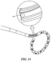
- Additional optional components for catheter shafts according to the present invention may include reinforcements such as for example a braid or coil embedded in or affixed to the catheter body, which may be made of any suitable material including metals and strong polymers. Specific examples of reinforcing materials may include stainless steel and nitinol. These reinforcing components may also be used to more strongly affix the steering wires to the catheter body, such as for example by embedding them into the wall of catheter body, inside or outside of (or even woven among) reinforcing components.
- Figure 15 also illustrates optional anchoring components, which may include a first and second anchoring ring 60 and 62, and which may be used to affix the steering wires to the catheter body.
- FIG. 16 Another example embodiment of a medical device according to the present disclosure is shown in Figure 16 , having a supplemental steering mechanism for more agile manipulation of the distal assembly.
- Catheter 76 has a handle assembly 78 having a first and second steering knob or actuator 80 and 82.
- First steering actuator 80 may be generally similar to steering actuator 28 of catheter 10, or may be generally similar to steering actuator 30 of catheter 12 with the addition of optional slider 84 for controlling a stiffener.
- Second steering actuator 82 may be used to bend and steer a more proximal portion of the catheter shaft, to more deftly position the distal assembly near a desired site of tissue for treatment.
- the second steering actuator 82 may enable bending and steering of a supplemental steering portion, which is proximal of the proximal portion of higher flexibility.
- FIG. 17 An embodiment of a medical device according to the present invention is shown in Figure 17 , having a supplemental steering mechanism in the form of a steerable catheter sheath 86, which at least partially surrounds an ablation catheter 88.
- Catheter 88 has a handle assembly 90 having a steering knob or actuator 92, and may have an optional slider 94.
- Catheter sheath 86 has a handle assembly 96 with a sheath steering knob or actuator 98.
- Catheter 88 and catheter sheath 86 may be moved, more specifically advanced, retracted or rotated, with respect to each other.
- the sheath steering actuator 98 may be used to bend and steer a selected portion of the catheter shaft, and sheath 86 may be moved so as to steer different portions of the catheter shaft.
- the distal treatment assembly 20 provides for the treatment, monitoring, or otherwise clinically interacting with a desired tissue region, such as the heart.
- the treatment assembly 20 may include, for example, an array or series of electrodes 22 disposed near, on, or substantially on the distal end of the catheter body.
- the electrodes 22 may be mounted to detect electrical signals between any pair of electrodes (bi-pole) for mapping of electrical activity, and/or for performing other functions such as pacing of the heart.
- the electrodes 22 may deliver ablation energy across an electrode pair or from independent electrodes when delivering monopolar energy.
- the plurality of electrodes may include from eight to twelve electrodes, with either symmetric or asymmetric spacing.
- the electrodes 22 may be constructed from platinum, iridium, or any other suitable material.
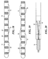
- Each electrode 22 may include a temperature sensor or thermocouple 72 located on or near the tissue side of the electrode, to monitor the temperature at each ablation site before and during ablation. Indeed, each electrode 22 may have a pair of thermocouples at radially or diametrically opposite points.
- the thermocouples are electrically connected to the handle assembly by conduits or wires, which may optionally be at least partially surrounded by a coil 74 shown in Figure 20 to improve signal fidelity.
- a quantity of the temperature sensors is at least equal to a quantity of the electrodes, and is at most twice the quantity of electrodes.
- thermocouples are arranged generally on one radial side of the catheter body, with two thermocouples on the radially opposite side of the catheter body. In Figure 19 , the thermocouples are positioned on alternating radially opposite sides of the catheter body.
Landscapes
- Health & Medical Sciences (AREA)
- Life Sciences & Earth Sciences (AREA)
- Surgery (AREA)
- Engineering & Computer Science (AREA)
- Plasma & Fusion (AREA)
- Medical Informatics (AREA)
- Otolaryngology (AREA)
- Physics & Mathematics (AREA)
- Cardiology (AREA)
- Biomedical Technology (AREA)
- Heart & Thoracic Surgery (AREA)
- Nuclear Medicine, Radiotherapy & Molecular Imaging (AREA)
- Molecular Biology (AREA)
- Animal Behavior & Ethology (AREA)
- General Health & Medical Sciences (AREA)
- Public Health (AREA)
- Veterinary Medicine (AREA)
- Surgical Instruments (AREA)
- Media Introduction/Drainage Providing Device (AREA)
Claims (14)
- Medizinische Vorrichtung (10), die Folgendes umfasst:einen Katheterkörper (18) mit einem ersten Abschnitt mit einer ersten Ebene bevorzugter Biegung und einem zweiten Abschnitt mit einer zweiten Ebene bevorzugter Biegung; wobei der erste Abschnitt distal von dem zweiten Abschnitt liegt;einen Lenkantrieb (28), der an den Katheterkörper (18) gekoppelt ist;wobei die medizinische Vorrichtung (10) einen ersten (34) und einen zweiten (36) Lenkmodus aufweist:wobei im ersten Lenkmodus die Bewegung des Lenkantriebs (28) aus einer Ausgangsstellung bewirkt, dass sich der erste Abschnitt entlang der ersten Ebene aus einer Ausgangsform in eine erste Bogenform biegt; undwobei im zweiten Lenkmodus die Bewegung des Lenkantriebs (28) aus der Ausgangsstellung bewirkt, dass sich der erste Abschnitt aus der Ausgangsform in eine zweite Bogenform biegt und bewirkt, dass sich der zweite Abschnitt entlang der zweiten Ebene biegt;eine lenkbare äußere Hülle (86), wobei die äußere Hülle (86) den Katheter mindestens teilweise umgibt und in Bezug darauf beweglich ist;eine Führungsplatte (64) in dem Katheterkörper (18) mit einem proximalen (66) und einem distalen (68) Abschnitt, die im Wesentlichen mit dem ersten bzw. dem zweiten Abschnitt des Katheterkörpers (18) koextensiv sind und durch einen Übergangsabschnitt (70) verbunden sind; wobei der proximale (66) und/oder der distale (68) Abschnitt der Führungsdrahtplatte (64) konkav ist; undeinen zweiten Lenkantrieb (82), der an die äußere Hülle (86) gekoppelt ist, wobei die Bewegung des zweiten Lenkantriebs (82) aus einer Ausgangsstellung bewirkt, dass sich ein Abschnitt der äußeren Hülle (86) aus einer Ausgangsform in eine Bogenform biegt.
- Medizinische Vorrichtung (10) nach Anspruch 1, weiter umfassend eine Vielzahl von Elektroden (22), die an dem ersten Abschnitt des Katheterkörpers (18) befestigt sind.
- Medizinische Vorrichtung (10) nach Anspruch 2, wobei die Elektroden (22) jeweils zu Kartierung, Schrittsteuerung und Abladieren in der Lage sind.
- Medizinische Vorrichtung (10) nach Anspruch 1, wobei die erste und die zweite Ebene ungefähr rechtwinklig sind.
- Medizinische Vorrichtung (10) nach Anspruch 1, wobei der Katheterkörper (18) mindestens vier Abschnitte mit abwechselnd höherer und geringerer Biegsamkeit aufweist; wobei der Übergangsabschnitt der Führungsplatte (64) in einem distalen Abschnitt mit höherer Biegsamkeit positioniert ist.
- Medizinische Vorrichtung (10) nach Anspruch 1, wobei der erste Lenkmodus gewählt wird, indem der Lenkantrieb (28) in einer ersten Richtung aus der Ausgangsstellung bewegt wird und der zweite Lenkmodus gewählt wird, indem der Lenkantrieb (28) in einer zweiten Richtung aus der Ausgangsstellung bewegt wird.
- Medizinische Vorrichtung (10) nach Anspruch 1, weiter umfassend ein Versteifungselement (48) in dem Katheterkörper (18); wobei der erste Lenkmodus gewählt wird, indem das Versteifungselement (48) in eine distale Lage bewegt wird und der zweite Lenkmodus gewählt wird, indem das Versteifungselement (48) in eine proximale Lage bewegt wird.
- Medizinische Vorrichtung (10) nach Anspruch 7, wobei sowohl im ersten als auch im zweiten Lenkmodus die Bewegung des Lenkantriebs (28) in einer ersten und einer zweiten Richtung bewirkt, dass sich der erste Abschnitt in einer ersten bzw. einer zweiten Richtung biegt.
- Medizinische Vorrichtung (10) nach Anspruch 1, weiter umfassend einen zweiten Lenkantrieb (82), der an den Katheterkörper (18) gekoppelt ist, wobei die Bewegung des zweiten Lenkantriebs (82) aus einer Ausgangsstellung bewirkt, dass sich ein Abschnitt des Katheterkörpers (18) proximal von dem zweiten Abschnitt aus einer Ausgangsform in eine Bogenform biegt.
- Medizinische Vorrichtung nach Anspruch 1, weiter umfassend ein erstes (34) und ein zweites (36) Lenkelement mit jeweils einem proximalen und einem distalen Ende; wobei die proximalen Enden des ersten (34) und des zweiten (36) Lenkelements mit dem Lenkantrieb (28) gekoppelt sind; wobei ein distaler Abschnitt des ersten (34) und des zweiten (36) Lenkelements jeweils an dem Katheterkörper (18) befestigt sind.
- Medizinische Vorrichtung (10) nach Anspruch 10, wobei die distalen Abschnitte des ersten (34) und des zweiten (36) Lenkelements an radial gegenüberliegenden Seiten des Katheterkörpers (18) folgendermaßen befestigt sind:(a) an einer Stelle in Längsrichtung; oder(b) an in Längsrichtung unterschiedlichen Stellen.
- Medizinische Vorrichtung (10) nach Anspruch 10, wobei die distalen Abschnitte des ersten (34) und des zweiten (36) Lenkelements an überlappenden Abschnitten des Katheterkörpers (18) befestigt sind:
- Medizinische Vorrichtung (10) nach Anspruch 12, wobei sich sowohl das erste (34) als auch das zweite (36) Lenkelement zu einem distalen Ende des Katheterkörpers erstrecken.
- Medizinische Vorrichtung (10) nach Anspruch 1, weiter umfassend eine Vielzahl von Temperatursensoren (72), wobei eine Anzahl der Temperatursensoren (72) mindestens gleich einer Anzahl der Elektroden (22) ist und höchstens das Zweifache der Anzahl der Elektroden (22) beträgt.
Applications Claiming Priority (2)
| Application Number | Priority Date | Filing Date | Title |
|---|---|---|---|
| US12/546,750 US9439721B2 (en) | 2009-08-25 | 2009-08-25 | Bi-modal linear and loop ablation catheter, and method |
| PCT/US2010/044191 WO2011025629A1 (en) | 2009-08-25 | 2010-08-03 | Bi-modal linear and loop ablation catheter, and method |
Publications (2)
| Publication Number | Publication Date |
|---|---|
| EP2470097A1 EP2470097A1 (de) | 2012-07-04 |
| EP2470097B1 true EP2470097B1 (de) | 2016-04-20 |
Family
ID=42760499
Family Applications (1)
| Application Number | Title | Priority Date | Filing Date |
|---|---|---|---|
| EP10749934.5A Not-in-force EP2470097B1 (de) | 2009-08-25 | 2010-08-03 | Bimodaler linear- und schlaufenablationskatheter sowie verfahren |
Country Status (5)
| Country | Link |
|---|---|
| US (2) | US9439721B2 (de) |
| EP (1) | EP2470097B1 (de) |
| CN (1) | CN102625675A (de) |
| CA (1) | CA2771590C (de) |
| WO (1) | WO2011025629A1 (de) |
Families Citing this family (38)
| Publication number | Priority date | Publication date | Assignee | Title |
|---|---|---|---|---|
| US7653438B2 (en) | 2002-04-08 | 2010-01-26 | Ardian, Inc. | Methods and apparatus for renal neuromodulation |
| US8774913B2 (en) | 2002-04-08 | 2014-07-08 | Medtronic Ardian Luxembourg S.A.R.L. | Methods and apparatus for intravasculary-induced neuromodulation |
| US8150519B2 (en) | 2002-04-08 | 2012-04-03 | Ardian, Inc. | Methods and apparatus for bilateral renal neuromodulation |
| US7258690B2 (en) | 2003-03-28 | 2007-08-21 | Relievant Medsystems, Inc. | Windowed thermal ablation probe |
| US8361067B2 (en) | 2002-09-30 | 2013-01-29 | Relievant Medsystems, Inc. | Methods of therapeutically heating a vertebral body to treat back pain |
| US6907884B2 (en) | 2002-09-30 | 2005-06-21 | Depay Acromed, Inc. | Method of straddling an intraosseous nerve |
| CA2957010C (en) | 2008-09-26 | 2017-07-04 | Relievant Medsystems, Inc. | Systems and methods for navigating an instrument through bone |
| US10028753B2 (en) | 2008-09-26 | 2018-07-24 | Relievant Medsystems, Inc. | Spine treatment kits |
| US8652129B2 (en) | 2008-12-31 | 2014-02-18 | Medtronic Ardian Luxembourg S.A.R.L. | Apparatus, systems, and methods for achieving intravascular, thermally-induced renal neuromodulation |
| US8870863B2 (en) | 2010-04-26 | 2014-10-28 | Medtronic Ardian Luxembourg S.A.R.L. | Catheter apparatuses, systems, and methods for renal neuromodulation |
| US9084610B2 (en) | 2010-10-21 | 2015-07-21 | Medtronic Ardian Luxembourg S.A.R.L. | Catheter apparatuses, systems, and methods for renal neuromodulation |
| JP2013544133A (ja) | 2010-10-25 | 2013-12-12 | メドトロニック アーディアン ルクセンブルク ソシエテ ア レスポンサビリテ リミテ | 腎ニューロモジュレーションのためのマルチ電極アレイを有するカテーテル装置ならびに関連のシステムおよび方法 |
| WO2013101772A1 (en) | 2011-12-30 | 2013-07-04 | Relievant Medsystems, Inc. | Systems and methods for treating back pain |
| US9717554B2 (en) * | 2012-03-26 | 2017-08-01 | Biosense Webster (Israel) Ltd. | Catheter with composite construction |
| US8888773B2 (en) | 2012-05-11 | 2014-11-18 | Medtronic Ardian Luxembourg S.A.R.L. | Multi-electrode catheter assemblies for renal neuromodulation and associated systems and methods |
| US10588691B2 (en) | 2012-09-12 | 2020-03-17 | Relievant Medsystems, Inc. | Radiofrequency ablation of tissue within a vertebral body |
| US9044575B2 (en) * | 2012-10-22 | 2015-06-02 | Medtronic Adrian Luxembourg S.a.r.l. | Catheters with enhanced flexibility and associated devices, systems, and methods |
| EP3578222B1 (de) | 2012-10-22 | 2024-06-19 | Medtronic Ardian Luxembourg S.à.r.l. | Katheter mit verbesserter flexibilität |
| CA2889478C (en) | 2012-11-05 | 2020-11-24 | Relievant Medsystems, Inc. | Systems and methods for creating curved paths through bone and modulating nerves within the bone |
| US9066726B2 (en) | 2013-03-15 | 2015-06-30 | Medtronic Ardian Luxembourg S.A.R.L. | Multi-electrode apposition judgment using pressure elements |
| US10548663B2 (en) | 2013-05-18 | 2020-02-04 | Medtronic Ardian Luxembourg S.A.R.L. | Neuromodulation catheters with shafts for enhanced flexibility and control and associated devices, systems, and methods |
| US9724151B2 (en) | 2013-08-08 | 2017-08-08 | Relievant Medsystems, Inc. | Modulating nerves within bone using bone fasteners |
| EP3099377B1 (de) | 2014-01-27 | 2022-03-02 | Medtronic Ireland Manufacturing Unlimited Company | Neuromodulationskatheter mit ummantelten neuromodulationselementen und zugehörige vorrichtungen |
| US10736690B2 (en) | 2014-04-24 | 2020-08-11 | Medtronic Ardian Luxembourg S.A.R.L. | Neuromodulation catheters and associated systems and methods |
| US10271899B2 (en) | 2015-03-18 | 2019-04-30 | Medtronic Cryocath Lp | Multi-function device with treatment and sensing capabilities |
| EP3398624A1 (de) * | 2017-05-04 | 2018-11-07 | Abiomed Europe GmbH | Blutpumpe mit verstärktem katheter |
| EP4725430A2 (de) * | 2017-06-19 | 2026-04-15 | St. Jude Medical, Cardiology Division, Inc. | Vorrichtungen zur hochdichten messung und ablation während eines medizinischen verfahrens |
| CN110327106A (zh) * | 2019-08-16 | 2019-10-15 | 西安市红会医院 | 一种椎体骨水泥注射装置 |
| EP4027912B1 (de) | 2019-09-12 | 2024-12-18 | Relievant Medsystems, Inc. | Systeme zur gewebemodulation |
| US11813414B2 (en) * | 2020-03-10 | 2023-11-14 | Stryker Corporation | Control systems for shapeable catheters |
| WO2022011115A1 (en) | 2020-07-10 | 2022-01-13 | Relievant Medsystems, Inc. | Vertebral denervation in conjunction with vertebral fusion |
| US12082876B1 (en) | 2020-09-28 | 2024-09-10 | Relievant Medsystems, Inc. | Introducer drill |
| AU2021409967A1 (en) | 2020-12-22 | 2023-08-03 | Relievant Medsystems, Inc. | Prediction of candidates for spinal neuromodulation |
| US12564440B2 (en) | 2021-04-26 | 2026-03-03 | Pulse Biosciences, Inc. | Multi-strut ablation and sensing catheter devices and methods |
| US12446944B2 (en) | 2021-04-26 | 2025-10-21 | Pulse Biosciences, Inc. | Mapping and ablation applicators |
| CA3215962A1 (en) | 2021-04-26 | 2022-11-03 | Roman Turovskiy | Circumferential ablation devices and methods |
| US12433668B1 (en) | 2021-11-08 | 2025-10-07 | Relievant Medsystems, Inc. | Impedance stoppage mitigation during radiofrequency tissue ablation procedures |
| CN116983077B (zh) * | 2023-07-06 | 2024-05-28 | 上海玮启医疗器械有限公司 | 一种可多段调弯的脉冲消融导管 |
Family Cites Families (29)
| Publication number | Priority date | Publication date | Assignee | Title |
|---|---|---|---|---|
| US6413234B1 (en) | 1990-02-02 | 2002-07-02 | Ep Technologies, Inc. | Assemblies for creating compound curves in distal catheter regions |
| US5820591A (en) * | 1990-02-02 | 1998-10-13 | E. P. Technologies, Inc. | Assemblies for creating compound curves in distal catheter regions |
| CN1052916C (zh) * | 1990-11-30 | 2000-05-31 | 黎浩钧 | 医用软性器件及其控制弯曲度的方法和装置 |
| AU660444B2 (en) * | 1991-02-15 | 1995-06-29 | Ingemar H. Lundquist | Torquable catheter and method |
| US5308342A (en) * | 1991-08-07 | 1994-05-03 | Target Therapeutics, Inc. | Variable stiffness catheter |
| US5855560A (en) * | 1991-11-08 | 1999-01-05 | Ep Technologies, Inc. | Catheter tip assembly |
| US5257451A (en) * | 1991-11-08 | 1993-11-02 | Ep Technologies, Inc. | Method of making durable sleeve for enclosing a bendable electrode tip assembly |
| US5555883A (en) | 1992-02-24 | 1996-09-17 | Avitall; Boaz | Loop electrode array mapping and ablation catheter for cardiac chambers |
| US5730127A (en) | 1993-12-03 | 1998-03-24 | Avitall; Boaz | Mapping and ablation catheter system |
| US5358479A (en) * | 1993-12-06 | 1994-10-25 | Electro-Catheter Corporation | Multiform twistable tip deflectable catheter |
| US6858024B1 (en) * | 1994-02-14 | 2005-02-22 | Scimed Life Systems, Inc. | Guide catheter having selected flexural modulus segments |
| JP3578460B2 (ja) * | 1994-06-27 | 2004-10-20 | ボストン サイエンティフィック リミテッド | 体内の温度を感知するためのシステム及び方法 |
| US20020156452A1 (en) * | 1996-02-16 | 2002-10-24 | Pursley Matt D. | Method and apparatus for curving catheter with soft distal end |
| AU8507698A (en) | 1997-07-29 | 1999-02-22 | Ep Technologies Inc | Improved catheter distal end assemblies |
| US6077258A (en) * | 1997-10-03 | 2000-06-20 | Scimed Life Systems, Inc. | Braided angiography catheter having full length radiopacity and controlled flexibility |
| US6156053A (en) * | 1998-05-01 | 2000-12-05 | Intella Interventional Systems, Inc. | Dual catheter assembly |
| US6592581B2 (en) | 1998-05-05 | 2003-07-15 | Cardiac Pacemakers, Inc. | Preformed steerable catheter with movable outer sleeve and method for use |
| WO2000076570A2 (en) * | 1999-06-15 | 2000-12-21 | Cryocath Technologies, Inc. | Steerable catheter |
| US7717899B2 (en) | 2002-01-28 | 2010-05-18 | Cardiac Pacemakers, Inc. | Inner and outer telescoping catheter delivery system |
| JP5328074B2 (ja) * | 2002-10-31 | 2013-10-30 | シー・アール・バード・インコーポレーテッド | 改善された電気生理学的カテーテル |
| US7013169B2 (en) * | 2003-01-27 | 2006-03-14 | Cardiac Pacemakers, Inc. | Dual steer preshaped catheter |
| US6980843B2 (en) | 2003-05-21 | 2005-12-27 | Stereotaxis, Inc. | Electrophysiology catheter |
| EP1866019B1 (de) | 2005-02-22 | 2017-10-25 | Cardiofocus, Inc. | Ablenkbare schleusenkatheter |
| WO2006102213A1 (en) * | 2005-03-18 | 2006-09-28 | Nmt Medical, Inc. | Catch member for pfo occluder |
| WO2007053625A1 (en) * | 2005-10-31 | 2007-05-10 | Wilson-Cook Medical Inc. | Steerable catheter devices and methods of articulating catheter devices |
| US8641704B2 (en) | 2007-05-11 | 2014-02-04 | Medtronic Ablation Frontiers Llc | Ablation therapy system and method for treating continuous atrial fibrillation |
| WO2009076461A1 (en) | 2007-12-10 | 2009-06-18 | Ablation Frontiers, Inc. | Rf energy delivery system and method |
| US20100049099A1 (en) * | 2008-07-18 | 2010-02-25 | Vytronus, Inc. | Method and system for positioning an energy source |
| WO2010028059A1 (en) | 2008-09-02 | 2010-03-11 | Medtronic Ablation Frontiers Llc | Irrigated ablation catheter system and methods |
-
2009
- 2009-08-25 US US12/546,750 patent/US9439721B2/en not_active Expired - Fee Related
-
2010
- 2010-08-03 WO PCT/US2010/044191 patent/WO2011025629A1/en not_active Ceased
- 2010-08-03 CA CA2771590A patent/CA2771590C/en not_active Expired - Fee Related
- 2010-08-03 EP EP10749934.5A patent/EP2470097B1/de not_active Not-in-force
- 2010-08-03 CN CN2010800481622A patent/CN102625675A/zh active Pending
-
2016
- 2016-08-19 US US15/241,750 patent/US20160354146A1/en not_active Abandoned
Also Published As
| Publication number | Publication date |
|---|---|
| CA2771590C (en) | 2017-05-09 |
| EP2470097A1 (de) | 2012-07-04 |
| US20110054464A1 (en) | 2011-03-03 |
| CN102625675A (zh) | 2012-08-01 |
| US20160354146A1 (en) | 2016-12-08 |
| CA2771590A1 (en) | 2011-03-03 |
| US9439721B2 (en) | 2016-09-13 |
| WO2011025629A1 (en) | 2011-03-03 |
Similar Documents
| Publication | Publication Date | Title |
|---|---|---|
| EP2470097B1 (de) | Bimodaler linear- und schlaufenablationskatheter sowie verfahren | |
| EP2470096B1 (de) | Bimodaler kathetersteuerunsmechanismus | |
| EP3122276B1 (de) | Asymmetrische katheterkurvenformen | |
| EP2797538B1 (de) | Katheter mit atraumatischer spitze | |
| US7606609B2 (en) | Devices and methods for cardiac mapping of an annular region | |
| EP2770933B1 (de) | Halbkreisförmiger lungenvenenablationskatheter | |
| US7419477B2 (en) | Catheterization method using proximal articulation and pre-formed distal end | |
| EP3466363B1 (de) | Katheter zur behandlung von vorhofflattern mit einfachwirkendem doppeldeflektionsmechanismus | |
| CN103417290B (zh) | 用于血管消融的具有螺旋状端部的导管 | |
| US11628009B2 (en) | EP catheter with trained support member, and related methods | |
| WO2000074555A2 (en) | Method and apparatus for performing cardiac ablations | |
| EP3381395B1 (de) | Katheter mit gleitender krümmung | |
| JP2004536628A (ja) | 入れ子式端部電極カテーテル |
Legal Events
| Date | Code | Title | Description |
|---|---|---|---|
| PUAI | Public reference made under article 153(3) epc to a published international application that has entered the european phase |
Free format text: ORIGINAL CODE: 0009012 |
|
| 17P | Request for examination filed |
Effective date: 20120326 |
|
| AK | Designated contracting states |
Kind code of ref document: A1 Designated state(s): AL AT BE BG CH CY CZ DE DK EE ES FI FR GB GR HR HU IE IS IT LI LT LU LV MC MK MT NL NO PL PT RO SE SI SK SM TR |
|
| DAX | Request for extension of the european patent (deleted) | ||
| 17Q | First examination report despatched |
Effective date: 20150312 |
|
| REG | Reference to a national code |
Ref country code: DE Ref legal event code: R079 Ref document number: 602010032526 Country of ref document: DE Free format text: PREVIOUS MAIN CLASS: A61B0018140000 Ipc: A61B0017000000 |
|
| GRAP | Despatch of communication of intention to grant a patent |
Free format text: ORIGINAL CODE: EPIDOSNIGR1 |
|
| RIC1 | Information provided on ipc code assigned before grant |
Ipc: A61B 17/00 20060101AFI20151016BHEP Ipc: A61B 18/14 20060101ALI20151016BHEP Ipc: A61B 18/00 20060101ALI20151016BHEP |
|
| INTG | Intention to grant announced |
Effective date: 20151105 |
|
| GRAS | Grant fee paid |
Free format text: ORIGINAL CODE: EPIDOSNIGR3 |
|
| GRAA | (expected) grant |
Free format text: ORIGINAL CODE: 0009210 |
|
| AK | Designated contracting states |
Kind code of ref document: B1 Designated state(s): AL AT BE BG CH CY CZ DE DK EE ES FI FR GB GR HR HU IE IS IT LI LT LU LV MC MK MT NL NO PL PT RO SE SI SK SM TR |
|
| REG | Reference to a national code |
Ref country code: GB Ref legal event code: FG4D |
|
| REG | Reference to a national code |
Ref country code: CH Ref legal event code: EP |
|
| REG | Reference to a national code |
Ref country code: AT Ref legal event code: REF Ref document number: 791479 Country of ref document: AT Kind code of ref document: T Effective date: 20160515 |
|
| REG | Reference to a national code |
Ref country code: IE Ref legal event code: FG4D |
|
| REG | Reference to a national code |
Ref country code: DE Ref legal event code: R096 Ref document number: 602010032526 Country of ref document: DE |
|
| REG | Reference to a national code |
Ref country code: LT Ref legal event code: MG4D Ref country code: FR Ref legal event code: PLFP Year of fee payment: 7 |
|
| REG | Reference to a national code |
Ref country code: AT Ref legal event code: MK05 Ref document number: 791479 Country of ref document: AT Kind code of ref document: T Effective date: 20160420 |
|
| REG | Reference to a national code |
Ref country code: NL Ref legal event code: MP Effective date: 20160420 |
|
| PG25 | Lapsed in a contracting state [announced via postgrant information from national office to epo] |
Ref country code: PL Free format text: LAPSE BECAUSE OF FAILURE TO SUBMIT A TRANSLATION OF THE DESCRIPTION OR TO PAY THE FEE WITHIN THE PRESCRIBED TIME-LIMIT Effective date: 20160420 Ref country code: LT Free format text: LAPSE BECAUSE OF FAILURE TO SUBMIT A TRANSLATION OF THE DESCRIPTION OR TO PAY THE FEE WITHIN THE PRESCRIBED TIME-LIMIT Effective date: 20160420 Ref country code: FI Free format text: LAPSE BECAUSE OF FAILURE TO SUBMIT A TRANSLATION OF THE DESCRIPTION OR TO PAY THE FEE WITHIN THE PRESCRIBED TIME-LIMIT Effective date: 20160420 Ref country code: NL Free format text: LAPSE BECAUSE OF FAILURE TO SUBMIT A TRANSLATION OF THE DESCRIPTION OR TO PAY THE FEE WITHIN THE PRESCRIBED TIME-LIMIT Effective date: 20160420 Ref country code: NO Free format text: LAPSE BECAUSE OF FAILURE TO SUBMIT A TRANSLATION OF THE DESCRIPTION OR TO PAY THE FEE WITHIN THE PRESCRIBED TIME-LIMIT Effective date: 20160720 |
|
| PG25 | Lapsed in a contracting state [announced via postgrant information from national office to epo] |
Ref country code: PT Free format text: LAPSE BECAUSE OF FAILURE TO SUBMIT A TRANSLATION OF THE DESCRIPTION OR TO PAY THE FEE WITHIN THE PRESCRIBED TIME-LIMIT Effective date: 20160822 Ref country code: AT Free format text: LAPSE BECAUSE OF FAILURE TO SUBMIT A TRANSLATION OF THE DESCRIPTION OR TO PAY THE FEE WITHIN THE PRESCRIBED TIME-LIMIT Effective date: 20160420 Ref country code: GR Free format text: LAPSE BECAUSE OF FAILURE TO SUBMIT A TRANSLATION OF THE DESCRIPTION OR TO PAY THE FEE WITHIN THE PRESCRIBED TIME-LIMIT Effective date: 20160721 Ref country code: ES Free format text: LAPSE BECAUSE OF FAILURE TO SUBMIT A TRANSLATION OF THE DESCRIPTION OR TO PAY THE FEE WITHIN THE PRESCRIBED TIME-LIMIT Effective date: 20160420 Ref country code: LV Free format text: LAPSE BECAUSE OF FAILURE TO SUBMIT A TRANSLATION OF THE DESCRIPTION OR TO PAY THE FEE WITHIN THE PRESCRIBED TIME-LIMIT Effective date: 20160420 Ref country code: HR Free format text: LAPSE BECAUSE OF FAILURE TO SUBMIT A TRANSLATION OF THE DESCRIPTION OR TO PAY THE FEE WITHIN THE PRESCRIBED TIME-LIMIT Effective date: 20160420 Ref country code: SE Free format text: LAPSE BECAUSE OF FAILURE TO SUBMIT A TRANSLATION OF THE DESCRIPTION OR TO PAY THE FEE WITHIN THE PRESCRIBED TIME-LIMIT Effective date: 20160420 |
|
| PG25 | Lapsed in a contracting state [announced via postgrant information from national office to epo] |
Ref country code: IT Free format text: LAPSE BECAUSE OF FAILURE TO SUBMIT A TRANSLATION OF THE DESCRIPTION OR TO PAY THE FEE WITHIN THE PRESCRIBED TIME-LIMIT Effective date: 20160420 Ref country code: BE Free format text: LAPSE BECAUSE OF FAILURE TO SUBMIT A TRANSLATION OF THE DESCRIPTION OR TO PAY THE FEE WITHIN THE PRESCRIBED TIME-LIMIT Effective date: 20160420 |
|
| REG | Reference to a national code |
Ref country code: DE Ref legal event code: R097 Ref document number: 602010032526 Country of ref document: DE |
|
| PG25 | Lapsed in a contracting state [announced via postgrant information from national office to epo] |
Ref country code: CZ Free format text: LAPSE BECAUSE OF FAILURE TO SUBMIT A TRANSLATION OF THE DESCRIPTION OR TO PAY THE FEE WITHIN THE PRESCRIBED TIME-LIMIT Effective date: 20160420 Ref country code: SK Free format text: LAPSE BECAUSE OF FAILURE TO SUBMIT A TRANSLATION OF THE DESCRIPTION OR TO PAY THE FEE WITHIN THE PRESCRIBED TIME-LIMIT Effective date: 20160420 Ref country code: EE Free format text: LAPSE BECAUSE OF FAILURE TO SUBMIT A TRANSLATION OF THE DESCRIPTION OR TO PAY THE FEE WITHIN THE PRESCRIBED TIME-LIMIT Effective date: 20160420 Ref country code: RO Free format text: LAPSE BECAUSE OF FAILURE TO SUBMIT A TRANSLATION OF THE DESCRIPTION OR TO PAY THE FEE WITHIN THE PRESCRIBED TIME-LIMIT Effective date: 20160420 Ref country code: DK Free format text: LAPSE BECAUSE OF FAILURE TO SUBMIT A TRANSLATION OF THE DESCRIPTION OR TO PAY THE FEE WITHIN THE PRESCRIBED TIME-LIMIT Effective date: 20160420 |
|
| PLBE | No opposition filed within time limit |
Free format text: ORIGINAL CODE: 0009261 |
|
| STAA | Information on the status of an ep patent application or granted ep patent |
Free format text: STATUS: NO OPPOSITION FILED WITHIN TIME LIMIT |
|
| PG25 | Lapsed in a contracting state [announced via postgrant information from national office to epo] |
Ref country code: SM Free format text: LAPSE BECAUSE OF FAILURE TO SUBMIT A TRANSLATION OF THE DESCRIPTION OR TO PAY THE FEE WITHIN THE PRESCRIBED TIME-LIMIT Effective date: 20160420 |
|
| 26N | No opposition filed |
Effective date: 20170123 |
|
| PG25 | Lapsed in a contracting state [announced via postgrant information from national office to epo] |
Ref country code: MC Free format text: LAPSE BECAUSE OF FAILURE TO SUBMIT A TRANSLATION OF THE DESCRIPTION OR TO PAY THE FEE WITHIN THE PRESCRIBED TIME-LIMIT Effective date: 20160420 |
|
| REG | Reference to a national code |
Ref country code: CH Ref legal event code: PL |
|
| GBPC | Gb: european patent ceased through non-payment of renewal fee |
Effective date: 20160803 |
|
| PG25 | Lapsed in a contracting state [announced via postgrant information from national office to epo] |
Ref country code: LI Free format text: LAPSE BECAUSE OF NON-PAYMENT OF DUE FEES Effective date: 20160831 Ref country code: CH Free format text: LAPSE BECAUSE OF NON-PAYMENT OF DUE FEES Effective date: 20160831 |
|
| PG25 | Lapsed in a contracting state [announced via postgrant information from national office to epo] |
Ref country code: SI Free format text: LAPSE BECAUSE OF FAILURE TO SUBMIT A TRANSLATION OF THE DESCRIPTION OR TO PAY THE FEE WITHIN THE PRESCRIBED TIME-LIMIT Effective date: 20160420 |
|
| REG | Reference to a national code |
Ref country code: IE Ref legal event code: MM4A |
|
| PG25 | Lapsed in a contracting state [announced via postgrant information from national office to epo] |
Ref country code: IE Free format text: LAPSE BECAUSE OF NON-PAYMENT OF DUE FEES Effective date: 20160803 Ref country code: GB Free format text: LAPSE BECAUSE OF NON-PAYMENT OF DUE FEES Effective date: 20160803 |
|
| REG | Reference to a national code |
Ref country code: FR Ref legal event code: PLFP Year of fee payment: 8 |
|
| PG25 | Lapsed in a contracting state [announced via postgrant information from national office to epo] |
Ref country code: LU Free format text: LAPSE BECAUSE OF NON-PAYMENT OF DUE FEES Effective date: 20160803 |
|
| PG25 | Lapsed in a contracting state [announced via postgrant information from national office to epo] |
Ref country code: HU Free format text: LAPSE BECAUSE OF FAILURE TO SUBMIT A TRANSLATION OF THE DESCRIPTION OR TO PAY THE FEE WITHIN THE PRESCRIBED TIME-LIMIT; INVALID AB INITIO Effective date: 20100803 Ref country code: CY Free format text: LAPSE BECAUSE OF FAILURE TO SUBMIT A TRANSLATION OF THE DESCRIPTION OR TO PAY THE FEE WITHIN THE PRESCRIBED TIME-LIMIT Effective date: 20160420 |
|
| PG25 | Lapsed in a contracting state [announced via postgrant information from national office to epo] |
Ref country code: TR Free format text: LAPSE BECAUSE OF FAILURE TO SUBMIT A TRANSLATION OF THE DESCRIPTION OR TO PAY THE FEE WITHIN THE PRESCRIBED TIME-LIMIT Effective date: 20160420 Ref country code: MT Free format text: LAPSE BECAUSE OF NON-PAYMENT OF DUE FEES Effective date: 20160831 Ref country code: MK Free format text: LAPSE BECAUSE OF FAILURE TO SUBMIT A TRANSLATION OF THE DESCRIPTION OR TO PAY THE FEE WITHIN THE PRESCRIBED TIME-LIMIT Effective date: 20160420 Ref country code: IS Free format text: LAPSE BECAUSE OF FAILURE TO SUBMIT A TRANSLATION OF THE DESCRIPTION OR TO PAY THE FEE WITHIN THE PRESCRIBED TIME-LIMIT Effective date: 20160420 |
|
| REG | Reference to a national code |
Ref country code: FR Ref legal event code: PLFP Year of fee payment: 9 |
|
| PG25 | Lapsed in a contracting state [announced via postgrant information from national office to epo] |
Ref country code: BG Free format text: LAPSE BECAUSE OF FAILURE TO SUBMIT A TRANSLATION OF THE DESCRIPTION OR TO PAY THE FEE WITHIN THE PRESCRIBED TIME-LIMIT Effective date: 20160420 |
|
| PG25 | Lapsed in a contracting state [announced via postgrant information from national office to epo] |
Ref country code: AL Free format text: LAPSE BECAUSE OF FAILURE TO SUBMIT A TRANSLATION OF THE DESCRIPTION OR TO PAY THE FEE WITHIN THE PRESCRIBED TIME-LIMIT Effective date: 20160420 |
|
| PGFP | Annual fee paid to national office [announced via postgrant information from national office to epo] |
Ref country code: DE Payment date: 20190722 Year of fee payment: 10 Ref country code: FR Payment date: 20190722 Year of fee payment: 10 |
|
| REG | Reference to a national code |
Ref country code: DE Ref legal event code: R119 Ref document number: 602010032526 Country of ref document: DE |
|
| PG25 | Lapsed in a contracting state [announced via postgrant information from national office to epo] |
Ref country code: FR Free format text: LAPSE BECAUSE OF NON-PAYMENT OF DUE FEES Effective date: 20200831 Ref country code: DE Free format text: LAPSE BECAUSE OF NON-PAYMENT OF DUE FEES Effective date: 20210302 |