EP2471146B1 - Steckvorrichtungssystem mit aktuator - Google Patents
Steckvorrichtungssystem mit aktuator Download PDFInfo
- Publication number
- EP2471146B1 EP2471146B1 EP10742809.6A EP10742809A EP2471146B1 EP 2471146 B1 EP2471146 B1 EP 2471146B1 EP 10742809 A EP10742809 A EP 10742809A EP 2471146 B1 EP2471146 B1 EP 2471146B1
- Authority
- EP
- European Patent Office
- Prior art keywords
- plug device
- actuator
- plug
- device system
- movement
- Prior art date
- Legal status (The legal status is an assumption and is not a legal conclusion. Google has not performed a legal analysis and makes no representation as to the accuracy of the status listed.)
- Active
Links
Images

Classifications
-
- H—ELECTRICITY
- H01—ELECTRIC ELEMENTS
- H01R—ELECTRICALLY-CONDUCTIVE CONNECTIONS; STRUCTURAL ASSOCIATIONS OF A PLURALITY OF MUTUALLY-INSULATED ELECTRICAL CONNECTING ELEMENTS; COUPLING DEVICES; CURRENT COLLECTORS
- H01R13/00—Details of coupling devices of the kinds covered by groups H01R12/70 or H01R24/00 - H01R33/00
- H01R13/62—Means for facilitating engagement or disengagement of coupling parts or for holding them in engagement
- H01R13/639—Additional means for holding or locking coupling parts together, after engagement, e.g. separate keylock, retainer strap
- H01R13/6395—Additional means for holding or locking coupling parts together, after engagement, e.g. separate keylock, retainer strap for wall or panel outlets
-
- B—PERFORMING OPERATIONS; TRANSPORTING
- B60—VEHICLES IN GENERAL
- B60L—PROPULSION OF ELECTRICALLY-PROPELLED VEHICLES; SUPPLYING ELECTRIC POWER FOR AUXILIARY EQUIPMENT OF ELECTRICALLY-PROPELLED VEHICLES; ELECTRODYNAMIC BRAKE SYSTEMS FOR VEHICLES IN GENERAL; MAGNETIC SUSPENSION OR LEVITATION FOR VEHICLES; MONITORING OPERATING VARIABLES OF ELECTRICALLY-PROPELLED VEHICLES; ELECTRIC SAFETY DEVICES FOR ELECTRICALLY-PROPELLED VEHICLES
- B60L53/00—Methods of charging batteries, specially adapted for electric vehicles; Charging stations or on-board charging equipment therefor; Exchange of energy storage elements in electric vehicles
- B60L53/10—Methods of charging batteries, specially adapted for electric vehicles; Charging stations or on-board charging equipment therefor; Exchange of energy storage elements in electric vehicles characterised by the energy transfer between the charging station and the vehicle
- B60L53/14—Conductive energy transfer
- B60L53/16—Connectors, e.g. plugs or sockets, specially adapted for charging electric vehicles
-
- B—PERFORMING OPERATIONS; TRANSPORTING
- B60—VEHICLES IN GENERAL
- B60L—PROPULSION OF ELECTRICALLY-PROPELLED VEHICLES; SUPPLYING ELECTRIC POWER FOR AUXILIARY EQUIPMENT OF ELECTRICALLY-PROPELLED VEHICLES; ELECTRODYNAMIC BRAKE SYSTEMS FOR VEHICLES IN GENERAL; MAGNETIC SUSPENSION OR LEVITATION FOR VEHICLES; MONITORING OPERATING VARIABLES OF ELECTRICALLY-PROPELLED VEHICLES; ELECTRIC SAFETY DEVICES FOR ELECTRICALLY-PROPELLED VEHICLES
- B60L2270/00—Problem solutions or means not otherwise provided for
- B60L2270/30—Preventing theft during charging
- B60L2270/32—Preventing theft during charging of electricity
-
- B—PERFORMING OPERATIONS; TRANSPORTING
- B60—VEHICLES IN GENERAL
- B60L—PROPULSION OF ELECTRICALLY-PROPELLED VEHICLES; SUPPLYING ELECTRIC POWER FOR AUXILIARY EQUIPMENT OF ELECTRICALLY-PROPELLED VEHICLES; ELECTRODYNAMIC BRAKE SYSTEMS FOR VEHICLES IN GENERAL; MAGNETIC SUSPENSION OR LEVITATION FOR VEHICLES; MONITORING OPERATING VARIABLES OF ELECTRICALLY-PROPELLED VEHICLES; ELECTRIC SAFETY DEVICES FOR ELECTRICALLY-PROPELLED VEHICLES
- B60L2270/00—Problem solutions or means not otherwise provided for
- B60L2270/30—Preventing theft during charging
- B60L2270/34—Preventing theft during charging of parts
-
- Y—GENERAL TAGGING OF NEW TECHNOLOGICAL DEVELOPMENTS; GENERAL TAGGING OF CROSS-SECTIONAL TECHNOLOGIES SPANNING OVER SEVERAL SECTIONS OF THE IPC; TECHNICAL SUBJECTS COVERED BY FORMER USPC CROSS-REFERENCE ART COLLECTIONS [XRACs] AND DIGESTS
- Y02—TECHNOLOGIES OR APPLICATIONS FOR MITIGATION OR ADAPTATION AGAINST CLIMATE CHANGE
- Y02T—CLIMATE CHANGE MITIGATION TECHNOLOGIES RELATED TO TRANSPORTATION
- Y02T10/00—Road transport of goods or passengers
- Y02T10/60—Other road transportation technologies with climate change mitigation effect
- Y02T10/70—Energy storage systems for electromobility, e.g. batteries
-
- Y—GENERAL TAGGING OF NEW TECHNOLOGICAL DEVELOPMENTS; GENERAL TAGGING OF CROSS-SECTIONAL TECHNOLOGIES SPANNING OVER SEVERAL SECTIONS OF THE IPC; TECHNICAL SUBJECTS COVERED BY FORMER USPC CROSS-REFERENCE ART COLLECTIONS [XRACs] AND DIGESTS
- Y02—TECHNOLOGIES OR APPLICATIONS FOR MITIGATION OR ADAPTATION AGAINST CLIMATE CHANGE
- Y02T—CLIMATE CHANGE MITIGATION TECHNOLOGIES RELATED TO TRANSPORTATION
- Y02T10/00—Road transport of goods or passengers
- Y02T10/60—Other road transportation technologies with climate change mitigation effect
- Y02T10/7072—Electromobility specific charging systems or methods for batteries, ultracapacitors, supercapacitors or double-layer capacitors
-
- Y—GENERAL TAGGING OF NEW TECHNOLOGICAL DEVELOPMENTS; GENERAL TAGGING OF CROSS-SECTIONAL TECHNOLOGIES SPANNING OVER SEVERAL SECTIONS OF THE IPC; TECHNICAL SUBJECTS COVERED BY FORMER USPC CROSS-REFERENCE ART COLLECTIONS [XRACs] AND DIGESTS
- Y02—TECHNOLOGIES OR APPLICATIONS FOR MITIGATION OR ADAPTATION AGAINST CLIMATE CHANGE
- Y02T—CLIMATE CHANGE MITIGATION TECHNOLOGIES RELATED TO TRANSPORTATION
- Y02T90/00—Enabling technologies or technologies with a potential or indirect contribution to GHG emissions mitigation
- Y02T90/10—Technologies relating to charging of electric vehicles
- Y02T90/14—Plug-in electric vehicles
Definitions
- the invention relates to a plug-in device system with a plug-in device element, for example a socket, and with an actuator for moving a target component in the plug-in device element.
- the invention further relates to a corresponding method for moving a target component in a plug-in device element, which is characterized in that an actuating force and / or a movement is transmitted from an actuator via a flexible coupling element to the target component.
- the described connector system and method utilize a flexible coupling element to transmit the force / movement generated at a first location (actuator) to a second location (connector element).
- actuator a first location
- connector element a second location
- the actuator and the plug-in device element can be arranged on different carriers, which can move independently of one another, for example, can vibrate relative to one another. Such relative movements between the carriers can namely be absorbed by the flexible coupling element, without the effect transmission from the actuator to the target component.
- a further advantage of the system is that it can be used in carrier systems of different geometry, since the flexible coupling element allows a plurality of relative positions of the actuator and the plug-in device element. In this way, the manufacturing costs can be reduced because the same plug-in device system can be used in different devices, housings, etc.
- the flexible coupling element can be realized in different ways.
- it may for example contain a cable, d. H. an elongated, strand-shaped and flexible member that is substantially rigid with respect to a tensile load in its axial direction.
- a cable is fastened with its two ends directly on the actuator component on the one hand or target component on the other hand, so that it can transmit a tensile force from the actuator component to the target component.
- the cable can for example consist of plastic or steel (ropes).
- the aforementioned cable is advantageously guided in a sleeve or sheath. On the one hand this protects the cable and prevents its contact with the environment. On the other hand, the mechanical properties of the sleeve can be chosen so that the effect of the cable changes in the desired manner. For example, if the sleeve is non-displaceable in its axial direction, tensile forces may be transmitted to the cable even when the cable extends on a curved path between the target and the actuator.
- the cable is designed so that it can transmit thrust in its axial direction.
- the cable can be equipped with a certain stiffness in the axial direction and be guided in particular in a sleeve of the type described above.
- this contains a hydraulic hose.
- a power transmission between the Aktuatorbauteil and the target component can then be done by virtue of the contained (incompressible) hydraulic fluid in the hose.
- the hydraulic hose preferably contains an electrically non-conductive hydraulic fluid, for example an oil. In this case, it is ensured that in case of leakage of the hydraulic hose, no short circuits in the electrical system of the plug-in device element or of the actuator can be caused.
- the coupling element is preferably (reversibly) releasably connected to the actuator and / or connected to the plug-in device element, for example via a screw, plug, or bayonet connection.
- the actuator may in particular be designed as an electromechanical actuator, d. H. as a device that converts electrical energy into mechanical energy (motion).
- an electromechanical actuator will contain at least one electromagnet, which in the current-carrying state can exert a magnetic attraction (eg on the actuator component).
- magnetic forces in a motor for example, it is also possible to generate rotational movements.
- the actuator is designed as a manually operable element.
- the actuator may include a push button, knob, lever, or the like, which may be actuated (moved) by a user and whose movement is then transmitted to the actuator component.
- the movement of the target component in the plug-in device element can serve different purposes.
- the target component could belong to an electrical switch, via which the contacts of the plug-in device element are switched to be current-free or current-carrying.
- the target component is designed such that it can lock an inserted complementary plug-in device element in a locking position and releases the plug movement of this complementary plug-in device element in an open position. In other words, the target component then serves the optional locking of a plug-in device in the assembled state.
- the target component may in particular be designed as a pin, which engages in the locking position in a recess (for example, in the groove or behind a nose) of an inserted complementary plug-in device element.
- the movement of this locking pin takes place in the radial direction (or with a component in the radial direction) with respect to the thru-axle between the considered plug-in device elements.
- the plug-in device element may in particular be a device socket, i. H. a coupling (with contact sockets), which is permanently installed in a device.
- a coupling with contact sockets
- the flexibility of the coupling element can be exploited to accommodate the connector system in devices of different geometries.
- the plug-in device system described can be configured in particular in the manner described above, ie have a flexible coupling element between the electromechanical actuator and the target component.
- the connector system according to the second aspect of the invention uses an electromechanical actuator to achieve locking of the connector in the inserted state. Compared to purely mechanical and manually operated locks this has the advantage that it allows automation of the locking process. This not only increases the comfort, but in particular the security, since a lock can not be forgotten or deliberately omitted.
- the electrical energy for the electromechanical actuator can be taken in particular from the power lines leading to the plug-in device element to be locked.
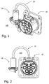
- the figures show in various views an example of a plug-in system 100 according to the invention.
- the connector system may be mounted on any support, such as a Housing, a wall, a device, or a vehicle. Details of this carrier are omitted in the figures for simplicity.
- FIG. 4 b shows in a detailed view of the connection of the coupling element 30 to the actuator 20.
- the coupling element 30 accordingly consists of a cable 32 which is guided axially displaceable in a sleeve 31 in the manner of a Bowden cable.
- the cable 32 is connected at its end to an actuator component 21, which is thereby formed an axially displaceable movable piston.
- an electromechanical mechanism not shown, for example, an electromagnet, the piston 21 in its axial direction (double arrow) can be moved. His movement and power are transferred to the cable 32.
- FIG. 4 a shows the other end of the coupling element 30 which is attached to the connector element 10.
- the cable 32 is connected to a target component of the plug-in device element, which is realized here as an axially displaceable movable pin 11.
- the pin 11 is in a locking position, in which it protrudes into the interior of the plug-in device element 10. If there is a plug plugged in as a complementary plug-in device element (not shown), the pin 11 can engage in a groove or behind a nose of this plug and lock it against inadvertent extract. A withdrawal of the pin 11 from the interior of the plug-in device element 10 in an open position, however, releases the movement of the inserted plug again.
- the described plug-in device system 100 has the advantage that it uses an electromechanical actuator 20 for locking a plug-in device. This makes it possible to automate the locking process and control it very flexibly.
- the plug-in device system 100 uses a flexible coupling element 30 between the actuator 20 and the plug-in device element 10. This has the advantage that the relative arrangement of the plug-in device element and the actuator is variable within wide limits, so that one and the same connector system can be installed in different environments. Furthermore, it is possible to arrange the actuator and the plug device element on different, relative to each other (in dimensions) movable supports. Last but not least, the coupling element 30 can also be produced in virtually any desired length so that the actuator and the plug-in device element can be arranged spatially far apart from one another.
Landscapes
- Engineering & Computer Science (AREA)
- Power Engineering (AREA)
- Transportation (AREA)
- Mechanical Engineering (AREA)
- Details Of Connecting Devices For Male And Female Coupling (AREA)
Description
- Die Erfindung betrifft ein Steckvorrichtungssystem mit einem Steckvorrichtungselement, beispielsweise einer Steckdose, sowie mit einem Aktuator zur Bewegung eines Zielbauteils in dem Steckvorrichtungselement.
- Bei Kraftsteckvorrichtungen (z. B. nach Norm DIN EN 60309) ist es bekannt, einen Stecker in einer Kupplung/Dose zu verriegeln, um ein unbeabsichtigtes Trennen der Steckvorrichtung zu verhindern.
- Aus der
US 5 711 558 ist ein induktives Ladesystem für ein Elektrofahrzeug bekannt, bei dem ein beweglicher Stift in die Ausnehmung eines Steckers eingreift und diesen dadurch verriegelt, wenn der Stecker in der zugehörigen Kupplung eingesteckt ist. Der Stift wird von einem Motor oder einer Spule über ein Kabel und einen Verzögerungsmechanismus betätigt. - Vor diesem Hintergrund war es Aufgabe der vorliegenden Erfindung, eine alternative Konstruktion einer Steckvorrichtung bereitzustellen, die sich insbesondere bei schwierigen bzw. engen Bauverhältnissen einsetzen lässt.
- Diese Aufgabe wird durch ein Steckvorrichtungssystem mit den Merkmalen des Anspruchs 1 sowie durch ein Verfahren mit den Merkmalen des Anspruchs 2 gelöst. Vorteilhafte Ausgestaltungen sind in den Unteransprüchen enthalten.
- Gemäß ihrem ersten Aspekt betrifft die Erfindung demnach ein Steckvorrichtungssystem mit den folgenden Komponenten:
- Einem Steckvorrichtungselement mit (mindestens) einem beweglichen Bauteil, welches im Folgenden als "Zielbauteil" bezeichnet wird. Der Ausdruck "Steckvorrichtungselement" soll dabei eine der komplementären Komponenten einer Steckvorrichtung bezeichnen, z. B. eine Dose bzw. Kupplung oder einen Stecker.
- Einen Aktuator zur aktiven und/oder passiven Bewegung eines zum Aktuator gehörenden Bauteils, welches im Folgenden "Aktuatorbauteil" genannt wird. Unter einer "aktiven Bewegung" wird dabei eine mechanische Bewegung verstanden, die im Aktuator selbst erzeugt wird, beispielsweise durch (elektro-)magnetische Kräfte. Im Gegensatz dazu soll eine "passive Bewegung" des Aktuatorbauteils dann vorliegen, wenn diese von einer Bewegung von Komponenten außerhalb des Aktuators verursacht wird. Letzteres ist beispielsweise bei einem manuell zu betätigenden Aktuator der Fall.
- Ein flexibles Kopplungselement zur Übertragung von Kraft und/oder Bewegung vom Aktuatorbauteil zum Zielbauteil. Die Flexibilität des Kopplungselementes bedeutet dabei, dass dieses (in Grenzen) Formveränderungen erfahren kann, ohne hierdurch in seiner Funktion der Kraft-/Bewegungsübertragung beeinträchtigt zu werden. Vorzugsweise sind die möglichen Formveränderungen so groß, dass sie die wahlweise Anordnung des Aktuatorbauteils an mindestens zwei verschiedenen, nicht überlappenden Positionen erlauben.
- Die Erfindung betrifft ferner ein korrespondierendes Verfahren zur Bewegung eines Zielbauteils in einem Steckvorrichtungselement, welches dadurch gekennzeichnet ist, dass eine Betätigungskraft und/oder eine Bewegung von einem Aktuator über ein flexibles Kopplungselement auf das Zielbauteil übertragen wird.
- Das beschriebene Steckvorrichtungssystem und das zugehörige Verfahren verwenden ein flexibles Kopplungselement, um die an einem ersten Ort (Aktuator) erzeugte Kraft/Bewegung an einen zweiten Ort (Steckvorrichtungselement) zu übertragen. Dies hat den Vorteil, dass der Aktuator und das Steckvorrichtungselement auf verschiedenen Trägern angeordnet sein können, die sich unabhängig voneinander bewegen, beispielsweise relativ zueinander vibrieren können. Derartige Relativbewegungen zwischen den Trägern können nämlich vom flexiblen Kopplungselement aufgefangen werden, ohne die Wirkungsübertragung vom Aktuator zum Zielbauteil zu stören. Ein weiterer Vorteil des Systems ist, dass es in Trägersystemen unterschiedlicher Geometrie eingesetzt werden kann, da das flexible Kopplungselement mehrere Relativpositionen von Aktuator und Steckvorrichtungselement zulässt. Auf diese Weise können die Herstellungskosten gesenkt werden, da dasselbe Steckvorrichtungssystem in unterschiedlichen Geräten, Gehäusen etc. eingesetzt werden kann.
- Im Folgenden werden verschiedene Weiterbildungen der Erfindung beschrieben, welche gleichermaßen für das Steckvorrichtungssystem wie für das zugehörige Verfahren angewendet werden können.
- Das flexible Kopplungselement lässt sich auf unterschiedliche Weisen realisieren. Gemäß einer ersten Ausführungsform kann es beispielsweise einen Seilzug enthalten, d. h. ein langgestrecktes, strangförmiges und flexibles Teil, das gegenüber einer Zugbelastung in seiner Axialrichtung im Wesentlichen starr ist. Typischerweise wird ein derartiger Seilzug mit seinen beiden Enden direkt am Aktuatorbauteil einerseits bzw. Zielbauteil andererseits befestigt, so dass er eine Zugkraft vom Aktuatorbauteil auf das Zielbauteil übertragen kann. Der Seilzug kann beispielsweise aus Kunststoff oder Stahl(seilen) bestehen.
- Der vorstehend genannte Seilzug wird vorteilhafterweise in einer Hülse oder Hülle geführt. Zum einen schützt dies den Seilzug und verhindert dessen Kontakt mit der Umgebung. Zum anderen können die mechanischen Eigenschaften der Hülse so gewählt werden, dass sich die Wirkung des Seilzuges in gewünschter Weise verändert. Wenn die Hülse beispielsweise in ihrer Axialrichtung längenunveränderlich ist, können Zugkräfte mit dem Seilzug auch dann übertragen werden, wenn der Seilzug sich auf gekrümmter Bahn zwischen Zielbauteil und Aktuatorbauteil erstreckt.
- Gemäß einer anderen Weiterbildung des Seilzuges ist dieser so ausgebildet, dass er in seiner Axialrichtung Schubkräfte übertragen kann. Hierzu kann der Seilzug mit einer gewissen Steifheit in Axialrichtung ausgestattet sein und insbesondere in einer Hülse der vorstehend beschriebenen Art geführt sein.
- Gemäß einer anderen Ausgestaltung des Kopplungselementes enthält dieses einen Hydraulikschlauch. Eine Kraftübertragung zwischen dem Aktuatorbauteil und dem Zielbauteil kann dann vermöge der im Schlauch enthaltenen (inkompressiblen) Hydraulikflüssigkeit erfolgen.
- Bei der vorstehend beschriebenen Ausführungsform enthält der Hydraulikschlauch vorzugsweise eine elektrisch nicht leitfähige Hydraulikflüssigkeit, beispielsweise ein Öl. In diesem Falle ist sichergestellt, dass bei einer Leckage des Hydraulikschlauches keine Kurzschlüsse im elektrischen System des Steckvorrichtungselementes oder des Aktuators verursacht werden können.
- Unabhängig von seiner konkreten Ausgestaltung ist das Kopplungselement vorzugsweise (reversibel) lösbar mit dem Aktuator und/oder mit dem Steckvorrichtungselement verbunden, beispielsweise über eine Schraub-, Steck-, oder Bajonettverbindung. Dies erleichtert zum einen die Montage des Steckvorrichtungssystems, da nicht alle seine drei Bestandteile (Steckvorrichtungselement, Kopplungselement, Aktuator) in einem Schritt montiert werden müssen, sondern dies zeitlich versetzt erfolgen kann. Zum anderen ist es auf diese Weise auch möglich, für Reparatur- oder Wartungszwecke die Komponenten des Systems einzeln auszutauschen.
- Der Aktuator kann insbesondere als ein elektromechanischer Aktuator ausgebildet sein, d. h. als ein Gerät, welches elektrische Energie in mechanische Energie (Bewegung) umwandelt. In der Regel wird ein solcher elektromechanischer Aktuator mindestens einen Elektromagneten enthalten, welcher im stromführenden Zustand eine magnetische Anziehungskraft (z. B. auf das Aktuatorbauteil) ausüben kann. Durch Magnetkräfte in einem Motor ist es beispielsweise auch möglich, Rotationsbewegungen zu erzeugen.
- Gemäß einer anderen Ausführungsform der Erfindung ist der Aktuator als ein manuell zu betätigendes Element ausgestaltet. Beispielsweise kann der Aktuator einen Druckknopf, Drehknopf, Hebel oder dergleichen enthalten, welcher von einem Benutzer betätigt (bewegt) werden kann und dessen Bewegung sich dann auf das Aktuatorbauteil überträgt.
- Die Bewegung des Zielbauteils im Steckvorrichtungselement kann unterschiedlichen Zwecken dienen. Beispielsweise könnte das Zielbauteil zu einem elektrischen Schalter gehören, über welchen die Kontakte des Steckvorrichtungselementes stromlos bzw. stromführend geschaltet werden. Gemäß einer bevorzugten Ausführungsform der Erfindung ist das Zielbauteil so ausgestaltet, dass es in einer Verriegelungsposition ein eingestecktes komplementäres Steckvorrichtungselement verriegeln kann und in einer Öffnungsposition die Steckbewegung dieses komplementären Steckvorrichtungselementes freigibt. Mit anderen Worten dient das Zielbauteil dann der wahlweisen Verriegelung einer Steckvorrichtung im zusammengesteckten Zustand.
- Im vorstehenden Ausführungsbeispiel kann das Zielbauteil insbesondere als ein Stift ausgebildet sein, der in der Verriegelungsposition in eine Ausnehmung (beispielsweise in die Nut oder hinter eine Nase) eines eingesteckten komplementären Steckvorrichtungselementes eingreift. Vorzugsweise erfolgt die Bewegung dieses Verriegelungsstiftes dabei in Radialrichtung (bzw. mit einer Komponente in Radialrichtung) in Bezug auf die Steckachse zwischen den betrachteten Steckvorrichtungselementen.
- Das Steckvorrichtungselement kann insbesondere eine Gerätedose sein, d. h. eine Kupplung (mit Kontaktbuchsen), die fest in ein Gerät eingebaut ist. In diesem Falle kann die Flexibilität des Kopplungselementes dazu ausgenutzt werden, das Steckvorrichtungssystem in Geräten unterschiedlicher Geometrien unterzubringen.
- Gemäß einem zweiten Aspekt betrifft die Erfindung ein Steckvorrichtungssystem mit den folgenden Komponenten:
- Einem Steckvorrichtungselement mit einem beweglichen Zielbauteil, das in einer Verriegelungsposition ein eingestecktes komplementäres Steckvorrichtungselement verriegeln kann, während es in einer Öffnungsposition den Steckvorgang freigibt.
- Einen elektromechanischen Aktuator zur aktiven Bewegung des Zielbauteils zwischen der Verriegelungsposition und der Öffnungsposition.
- Das beschriebene Steckvorrichtungssystem kann insbesondere in der oben beschriebenen Weise ausgestaltet sein, also zwischen dem elektromechanischen Aktuator und dem Zielbauteil ein flexibles Kopplungselement aufweisen. Bezüglich der Einzelheiten, Definitionen und Modifikationen kann im Übrigen auch auf die obige Beschreibung verwiesen werden. Das Steckvorrichtungssystem gemäß dem zweiten Aspekt der Erfindung verwendet einen elektromechanischen Aktuator, um eine Verriegelung der Steckvorrichtung im eingesteckten Zustand zu erreichen. Gegenüber rein mechanischen und manuell zu betätigenden Verriegelungen hat dies den Vorteil, dass es eine Automatisierung des Verriegelungsvorganges zulässt. Dies erhöht nicht nur den Komfort, sondern insbesondere auch die Sicherheit, da ein Verriegeln nicht vergessen oder absichtlich unterlassen werden kann. Die elektrische Energie für den elektromechanischen Aktuator kann insbesondere aus den Stromleitungen entnommen werden, die zu dem zu verriegelnden Steckvorrichtungselement führen.
- Im Folgenden wird die Erfindung mit Hilfe der Figuren beispielhaft näher erläutert. Dabei zeigt:
- Fig. 1
- in einer perspektivischen Ansicht ein Steckvorrichtungssystem gemäß einer Ausführungsform der vorliegenden Erfindung;
- Fig. 2
- das Steckvorrichtungssystem in einer Frontansicht;
- Fig. 3
- das Steckvorrichtungssystem in einer Seitenansicht;
- Fig. 4
- (a) das Verriegelungssystem und (b) den Aktuator des Steckvorrichtungssystems in einem Schnitt entlang der Linie IV-IV von
Figur 3 . - Die Figuren zeigen in verschiedenen Ansichten ein Beispiel für ein Steckvorrichtungssystem 100 gemäß der Erfindung. Das Steckvorrichtungssystem kann an einem beliebigen Träger montiert sein kann, beispielsweise einem Gehäuse, einer Wand, einem Gerät, oder einem Fahrzeug. Einzelheiten dieses Trägers sind in den Figuren zur Vereinfachung weggelassen.
- Das Steckvorrichtungssystem 100 umfasst die folgenden drei Hauptkomponenten:
- Ein Steckvorrichtungselement 10, hier in Form einer Kraftsteckvorrichtungsdose mit mehreren Kontakten (Buchsen).
- Einen Aktuator 20.
- Ein flexibles Kopplungselement 30, welches den Aktuator 20 mit dem Steckvorrichtungselement 10 verbindet.
-
Figur 4 b) zeigt in einer Detailansicht die Anbindung des Kopplungselementes 30 an den Aktuator 20. Das Kopplungselement 30 besteht demnach aus einem Seilzug 32, der in einer Hülse 31 nach Art eines Bowdenzuges axial verschiebebeweglich geführt ist. Der Seilzug 32 ist an seinem Ende mit einem Aktuatorbauteil 21 verbunden, das hierdurch einen axial verschiebebeweglichen Kolben gebildet wird. Durch einen nicht näher dargestellten elektromechanischen Mechanismus, beispielsweise einen Elektromagneten, kann der Kolben 21 in seiner Axialrichtung (Doppelpfeil) verschoben werden. Seine Bewegung und Kraft übertragen sich dabei auf den Seilzug 32. -
Figur 4 a) zeigt das andere Ende des Kopplungselementes 30, das am Steckvorrichtungselement 10 angebracht ist. Der Seilzug 32 ist dabei mit einem Zielbauteil des Steckvorrichtungselementes verbunden, das hier als ein axial verschiebebeweglicher Stift 11 realisiert ist. In der Darstellung befindet sich der Stift 11 in einer Verriegelungsposition, in welcher er in das Innere des Steckvorrichtungselementes 10 hineinragt. Wenn dort ein Stecker als komplementäres Steckvorrichtungselement eingesteckt ist (nicht dargestellt), kann der Stift 11 in eine Nut oder hinter eine Nase dieses Steckers eingreifen und ihn so gegen einen unbeabsichtigten Auszug verriegeln. Ein Rückzug des Stiftes 11 aus dem Inneren des Steckvorrichtungselementes 10 in eine Öffnungsposition gibt dagegen die Bewegung des eingesteckten Steckers wieder frei. - Das beschriebene Steckvorrichtungssystem 100 hat den Vorteil, dass es einen elektromechanischen Aktuator 20 zur Verriegelung einer Steckvorrichtung verwendet. Hierdurch lässt sich der Verriegelungsvorgang automatisieren und sehr flexibel steuern. Gemäß einem zweiten, davon unabhängigen Aspekt verwendet das Steckvorrichtungssystem 100 zwischen dem (hier elektromechanisch ausgebildeten) Aktuator 20 und dem Steckvorrichtungselement 10 ein flexibles Kopplungselement 30. Dies hat den Vorteil, dass die relative Anordnung von Steckvorrichtungselement und Aktuator in weiten Grenzen variabel ist, so dass ein und dasselbe Steckvorrichtungssystem in unterschiedlichen Umgebungen verbaut werden kann. Des Weiteren ist es möglich, den Aktuator und das Steckvorrichtungselement auf unterschiedlichen, relativ zueinander (in Maßen) beweglichen Trägern anzuordnen. Nicht zuletzt kann das Kopplungselement 30 auch in nahezu jeder beliebigen Länge hergestellt werden, so dass Aktuator und Steckvorrichtungselement räumlich weit voneinander entfernt angeordnet werden können.
Claims (13)
- Steckvorrichtungssystem (100), umfassend:- ein Steckvorrichtungselement (10) mit einem zugehörigen beweglichen Zielbauteil (11);- einen Aktuator (20) zur aktiven und/oder passiven Bewegung eines Aktuatorbauteils (21);gekennzeichnet durch- ein flexibles Kopplungselement (30) zur Übertragung von Kraft und/oder Bewegung vom Aktuatorbauteil zum Zielbauteil;- die Anordnung von Aktuator (20) und Steckvorrichtungselement (10) auf verschiedenen Trägern, die sich unabhängig voneinander bewegen können.
- Verfahren zur Bewegung eines zu einem Steckvorrichtungselement (10) gehörenden Zielbauteils (11) in dem genannten Steckvorrichtungselement (10),
dadurch gekennzeichnet, dass eine Betätigungskraft und/oder eine Bewegung von einem Aktuator (20) über ein flexibles Kopplungselement (30) auf das Zielbauteil (11) übertragen wird, wobei der Aktuator (20) und das Steckvorrichtungselement (10) auf verschiedenen Trägern angeordnet sind, die sich unabhängig voneinander bewegen können. - Steckvorrichtungssystem (100) nach Anspruch 1,
dadurch gekennzeichnet, dass das Kopplungselement (30) einen Seilzug (32) enthält. - Steckvorrichtungssystem (100) nach Anspruch 3,
dadurch gekennzeichnet, dass der Seilzug (32) in einer Hülse (31) geführt wird. - Steckvorrichtungssystem (100) nach Anspruch 4 oder 5,
dadurch gekennzeichnet, dass der Seilzug (32) in Axialrichtung Schubkräfte übertragen kann. - Steckvorrichtungssystem (100) nach Anspruch 1,
dadurch gekennzeichnet, dass das Kopplungselement (30) einen Hydraulikschlauch enthält. - Steckvorrichtungssystem (100) nach Anspruch 6,
dadurch gekennzeichnet, dass die Hydraulik eine elektrisch nicht leitfähige Flüssigkeit enthält. - Steckvorrichtungssystem (100) nach einem der Ansprüche 1 oder 3-7,
dadurch gekennzeichnet, dass das Kopplungselement (30) lösbar mit den Aktuator (20) und/oder dem Steckvorrichtungselement (10) verbunden ist. - Steckvorrichtungssystem (100) nach einem der Ansprüche 1 oder 3-8,
dadurch gekennzeichnet, dass der Aktuator ein elektromechanischer Aktuator (20) ist. - Steckvorrichtungssystem (100) nach einem der Ansprüche 1 oder 3-8,
dadurch gekennzeichnet, dass der Aktuator ein manuell zu betätigendes Element ist. - Verfahren nach Anspruch 2,
dadurch gekennzeichnet, dass das Zielbauteil (11) in einer Verriegelungsposition ein eingestecktes komplementäres Steckvorrichtungselement verriegeln kann und in einer Öffnungsposition dessen Steckvorgang freigibt. - Steckvorrichtungssystem (100) nach einem der Ansprüche 1 oder 3-10,
dadurch gekennzeichnet, dass das Zielbauteil ein Stift (11) ist, der in einer Verriegelungsposition in die Nut oder hinter eine Nase eines eingesteckten komplementären Steckvorrichtungselementes eingreift. - Steckvorrichtungssystem (100) nach einem der Ansprüche 1, 3-10, oder 12,
dadurch gekennzeichnet, dass das Steckvorrichtungselement (10) eine Gerätedose ist.
Applications Claiming Priority (2)
| Application Number | Priority Date | Filing Date | Title |
|---|---|---|---|
| DE102009043845A DE102009043845A1 (de) | 2009-08-25 | 2009-08-25 | Steckvorrichtungssystem mit Aktuator |
| PCT/EP2010/061366 WO2011023514A1 (de) | 2009-08-25 | 2010-08-04 | Steckvorrichtungssystem mit aktuator |
Publications (2)
| Publication Number | Publication Date |
|---|---|
| EP2471146A1 EP2471146A1 (de) | 2012-07-04 |
| EP2471146B1 true EP2471146B1 (de) | 2016-08-31 |
Family
ID=42982071
Family Applications (1)
| Application Number | Title | Priority Date | Filing Date |
|---|---|---|---|
| EP10742809.6A Active EP2471146B1 (de) | 2009-08-25 | 2010-08-04 | Steckvorrichtungssystem mit aktuator |
Country Status (5)
| Country | Link |
|---|---|
| EP (1) | EP2471146B1 (de) |
| CN (1) | CN102625967B (de) |
| DE (1) | DE102009043845A1 (de) |
| ES (1) | ES2603557T3 (de) |
| WO (1) | WO2011023514A1 (de) |
Cited By (1)
| Publication number | Priority date | Publication date | Assignee | Title |
|---|---|---|---|---|
| US20240001781A1 (en) * | 2020-12-02 | 2024-01-04 | Kiekert Ag | Charging device for a motor vehicle |
Families Citing this family (8)
| Publication number | Priority date | Publication date | Assignee | Title |
|---|---|---|---|---|
| DE102011050536A1 (de) * | 2011-05-20 | 2012-11-22 | Phoenix Contact Gmbh & Co. Kg | Steckverbinder |
| DE102011050938A1 (de) * | 2011-06-08 | 2012-12-13 | Phoenix Contact Gmbh & Co. Kg | Kabelstecker |
| DE102011056130A1 (de) * | 2011-12-07 | 2013-06-13 | Huf Hülsbeck & Fürst Gmbh & Co. Kg | Verriegelungsvorrichtung für einen Ladestecker eines elektrisch betriebenen Kraftfahrzeugs |
| DE112013005072T5 (de) | 2012-10-19 | 2015-07-02 | Lear Corporation | Elektrische Verbinderbaugruppe |
| DE102015108831A1 (de) * | 2015-06-03 | 2016-12-08 | Huf Hülsbeck & Fürst Gmbh & Co. Kg | Verriegelungssystem für einen Ladestecker |
| CN105846246A (zh) * | 2016-05-03 | 2016-08-10 | 深圳市华鸿贤精密技术有限公司 | 一种汽车充电插座 |
| CN107548245A (zh) * | 2016-06-24 | 2018-01-05 | 中兴通讯股份有限公司 | 可拆卸终端及拆卸、安装终端的方法 |
| EP3763558A1 (de) * | 2019-07-09 | 2021-01-13 | Jabil Inc. | Elektromechanischer aktuator zum verriegeln eines ladekabels in einer ladeaufnahme |
Citations (1)
| Publication number | Priority date | Publication date | Assignee | Title |
|---|---|---|---|---|
| US5711558A (en) * | 1996-08-26 | 1998-01-27 | Delco Electronics Corporation | Charger locking mechanism |
Family Cites Families (5)
| Publication number | Priority date | Publication date | Assignee | Title |
|---|---|---|---|---|
| US4063790A (en) * | 1976-10-15 | 1977-12-20 | Dayco Corporation | Fluid conduit assembly |
| JP2916348B2 (ja) * | 1993-07-22 | 1999-07-05 | 住友電装株式会社 | 電気自動車充電用コネクタ |
| US5641298A (en) * | 1995-08-01 | 1997-06-24 | Holloway; Steven E. | Locking device for plug-socket electrical connector |
| US7775801B2 (en) * | 2005-01-05 | 2010-08-17 | Microsoft Corporation | Device interfaces with non-mechanical securement mechanisms |
| CN201061021Y (zh) * | 2007-05-18 | 2008-05-14 | 浙江天台永贵电器有限公司 | 连接器锁紧装置 |
-
2009
- 2009-08-25 DE DE102009043845A patent/DE102009043845A1/de not_active Withdrawn
-
2010
- 2010-08-04 ES ES10742809.6T patent/ES2603557T3/es active Active
- 2010-08-04 WO PCT/EP2010/061366 patent/WO2011023514A1/de not_active Ceased
- 2010-08-04 EP EP10742809.6A patent/EP2471146B1/de active Active
- 2010-08-04 CN CN201080038332.9A patent/CN102625967B/zh active Active
Patent Citations (1)
| Publication number | Priority date | Publication date | Assignee | Title |
|---|---|---|---|---|
| US5711558A (en) * | 1996-08-26 | 1998-01-27 | Delco Electronics Corporation | Charger locking mechanism |
Cited By (1)
| Publication number | Priority date | Publication date | Assignee | Title |
|---|---|---|---|---|
| US20240001781A1 (en) * | 2020-12-02 | 2024-01-04 | Kiekert Ag | Charging device for a motor vehicle |
Also Published As
| Publication number | Publication date |
|---|---|
| EP2471146A1 (de) | 2012-07-04 |
| CN102625967B (zh) | 2016-02-10 |
| HK1172999A1 (zh) | 2013-05-03 |
| ES2603557T3 (es) | 2017-02-28 |
| CN102625967A (zh) | 2012-08-01 |
| DE102009043845A1 (de) | 2011-03-03 |
| WO2011023514A1 (de) | 2011-03-03 |
Similar Documents
| Publication | Publication Date | Title |
|---|---|---|
| EP2471146B1 (de) | Steckvorrichtungssystem mit aktuator | |
| EP3275053B1 (de) | Modularer steckverbinder | |
| DE10230379A1 (de) | Elektrokontaktkupplung | |
| DE102009053674A1 (de) | Steckverbinder mit Sekundärsteckverbinder | |
| DE102009011904A1 (de) | Verbindungsvorrichtung | |
| EP3046800A1 (de) | Elektromechanische verriegelungsvorrichtung | |
| EP2144337B1 (de) | Vorrichtung zur elektrischen Verbindung | |
| DE102021003654A1 (de) | Ladeanschlussvorrichtung für ein elektrisch antreibbares Fahrzeug | |
| DE102011083819B4 (de) | Verriegelungseinrichtung für ein Kraftfahrzeug | |
| DE112007000611B4 (de) | Elektrischer Steckverbinder und elektrische Steckverbindung mit unterschiedlichen Eingriffs- und operativen Rückhaltekraften | |
| EP2449302B1 (de) | Kupplungsanordnung | |
| DE102017001943A1 (de) | Anschlusssystem | |
| EP3078082B1 (de) | Steckverbinder mit steckkraftbegrenzung | |
| EP3427347B1 (de) | Elektrische steckverbindung | |
| WO2021028150A1 (de) | Elektrozugkupplung und zugkupplung mit einer solchen elektrozugkupplung | |
| EP2504890A1 (de) | Leicht zu reinigender steckverbinder | |
| EP3408898B1 (de) | Elektrische steckverbindung | |
| DE102011052213B4 (de) | Kontakteinsetzanordnung | |
| DE102013019798A1 (de) | Steckverbinderanordnung | |
| DE102012101687A1 (de) | Gerätestecker | |
| EP4057450B1 (de) | Elektrogerät mit einer abdeckkappe mit integriertem magnetischem kontaktierungsmittel | |
| DE102015010626A1 (de) | Entriegelungsvorrichtung für eine Fahrzeugtür, Fahrzeugtür und Verfahren zum Betreiben einer Entriegelungsvorrichtung | |
| DE102023112467A1 (de) | Steckverbindung zum Laden eines Elektrofahrzeugs | |
| EP2933810B1 (de) | Schalter | |
| EP2562885A2 (de) | Stecker mit Anpressfedervorrichtung zur elektrischen Direktkontaktierung einer Leiterplatte |
Legal Events
| Date | Code | Title | Description |
|---|---|---|---|
| PUAI | Public reference made under article 153(3) epc to a published international application that has entered the european phase |
Free format text: ORIGINAL CODE: 0009012 |
|
| 17P | Request for examination filed |
Effective date: 20120221 |
|
| AK | Designated contracting states |
Kind code of ref document: A1 Designated state(s): AL AT BE BG CH CY CZ DE DK EE ES FI FR GB GR HR HU IE IS IT LI LT LU LV MC MK MT NL NO PL PT RO SE SI SK SM TR |
|
| DAX | Request for extension of the european patent (deleted) | ||
| 17Q | First examination report despatched |
Effective date: 20151207 |
|
| GRAP | Despatch of communication of intention to grant a patent |
Free format text: ORIGINAL CODE: EPIDOSNIGR1 |
|
| RIC1 | Information provided on ipc code assigned before grant |
Ipc: H01R 13/639 20060101AFI20160217BHEP Ipc: B60L 11/18 20060101ALI20160217BHEP |
|
| INTG | Intention to grant announced |
Effective date: 20160321 |
|
| GRAS | Grant fee paid |
Free format text: ORIGINAL CODE: EPIDOSNIGR3 |
|
| GRAA | (expected) grant |
Free format text: ORIGINAL CODE: 0009210 |
|
| AK | Designated contracting states |
Kind code of ref document: B1 Designated state(s): AL AT BE BG CH CY CZ DE DK EE ES FI FR GB GR HR HU IE IS IT LI LT LU LV MC MK MT NL NO PL PT RO SE SI SK SM TR |
|
| REG | Reference to a national code |
Ref country code: CH Ref legal event code: EP Ref country code: GB Ref legal event code: FG4D Free format text: NOT ENGLISH |
|
| REG | Reference to a national code |
Ref country code: IE Ref legal event code: FG4D Free format text: LANGUAGE OF EP DOCUMENT: GERMAN |
|
| REG | Reference to a national code |
Ref country code: DE Ref legal event code: R096 Ref document number: 502010012312 Country of ref document: DE |
|
| REG | Reference to a national code |
Ref country code: AT Ref legal event code: REF Ref document number: 825704 Country of ref document: AT Kind code of ref document: T Effective date: 20161015 |
|
| REG | Reference to a national code |
Ref country code: SE Ref legal event code: TRGR |
|
| REG | Reference to a national code |
Ref country code: LT Ref legal event code: MG4D |
|
| REG | Reference to a national code |
Ref country code: NL Ref legal event code: MP Effective date: 20160831 |
|
| PG25 | Lapsed in a contracting state [announced via postgrant information from national office to epo] |
Ref country code: HR Free format text: LAPSE BECAUSE OF FAILURE TO SUBMIT A TRANSLATION OF THE DESCRIPTION OR TO PAY THE FEE WITHIN THE PRESCRIBED TIME-LIMIT Effective date: 20160831 Ref country code: NO Free format text: LAPSE BECAUSE OF FAILURE TO SUBMIT A TRANSLATION OF THE DESCRIPTION OR TO PAY THE FEE WITHIN THE PRESCRIBED TIME-LIMIT Effective date: 20161130 Ref country code: LT Free format text: LAPSE BECAUSE OF FAILURE TO SUBMIT A TRANSLATION OF THE DESCRIPTION OR TO PAY THE FEE WITHIN THE PRESCRIBED TIME-LIMIT Effective date: 20160831 Ref country code: FI Free format text: LAPSE BECAUSE OF FAILURE TO SUBMIT A TRANSLATION OF THE DESCRIPTION OR TO PAY THE FEE WITHIN THE PRESCRIBED TIME-LIMIT Effective date: 20160831 |
|
| PG25 | Lapsed in a contracting state [announced via postgrant information from national office to epo] |
Ref country code: GR Free format text: LAPSE BECAUSE OF FAILURE TO SUBMIT A TRANSLATION OF THE DESCRIPTION OR TO PAY THE FEE WITHIN THE PRESCRIBED TIME-LIMIT Effective date: 20161201 Ref country code: LV Free format text: LAPSE BECAUSE OF FAILURE TO SUBMIT A TRANSLATION OF THE DESCRIPTION OR TO PAY THE FEE WITHIN THE PRESCRIBED TIME-LIMIT Effective date: 20160831 Ref country code: NL Free format text: LAPSE BECAUSE OF FAILURE TO SUBMIT A TRANSLATION OF THE DESCRIPTION OR TO PAY THE FEE WITHIN THE PRESCRIBED TIME-LIMIT Effective date: 20160831 |
|
| REG | Reference to a national code |
Ref country code: ES Ref legal event code: FG2A Ref document number: 2603557 Country of ref document: ES Kind code of ref document: T3 Effective date: 20170228 |
|
| PG25 | Lapsed in a contracting state [announced via postgrant information from national office to epo] |
Ref country code: EE Free format text: LAPSE BECAUSE OF FAILURE TO SUBMIT A TRANSLATION OF THE DESCRIPTION OR TO PAY THE FEE WITHIN THE PRESCRIBED TIME-LIMIT Effective date: 20160831 Ref country code: RO Free format text: LAPSE BECAUSE OF FAILURE TO SUBMIT A TRANSLATION OF THE DESCRIPTION OR TO PAY THE FEE WITHIN THE PRESCRIBED TIME-LIMIT Effective date: 20160831 |
|
| PG25 | Lapsed in a contracting state [announced via postgrant information from national office to epo] |
Ref country code: SK Free format text: LAPSE BECAUSE OF FAILURE TO SUBMIT A TRANSLATION OF THE DESCRIPTION OR TO PAY THE FEE WITHIN THE PRESCRIBED TIME-LIMIT Effective date: 20160831 Ref country code: DK Free format text: LAPSE BECAUSE OF FAILURE TO SUBMIT A TRANSLATION OF THE DESCRIPTION OR TO PAY THE FEE WITHIN THE PRESCRIBED TIME-LIMIT Effective date: 20160831 Ref country code: PT Free format text: LAPSE BECAUSE OF FAILURE TO SUBMIT A TRANSLATION OF THE DESCRIPTION OR TO PAY THE FEE WITHIN THE PRESCRIBED TIME-LIMIT Effective date: 20170102 Ref country code: CZ Free format text: LAPSE BECAUSE OF FAILURE TO SUBMIT A TRANSLATION OF THE DESCRIPTION OR TO PAY THE FEE WITHIN THE PRESCRIBED TIME-LIMIT Effective date: 20160831 Ref country code: BG Free format text: LAPSE BECAUSE OF FAILURE TO SUBMIT A TRANSLATION OF THE DESCRIPTION OR TO PAY THE FEE WITHIN THE PRESCRIBED TIME-LIMIT Effective date: 20161130 Ref country code: SM Free format text: LAPSE BECAUSE OF FAILURE TO SUBMIT A TRANSLATION OF THE DESCRIPTION OR TO PAY THE FEE WITHIN THE PRESCRIBED TIME-LIMIT Effective date: 20160831 Ref country code: PL Free format text: LAPSE BECAUSE OF FAILURE TO SUBMIT A TRANSLATION OF THE DESCRIPTION OR TO PAY THE FEE WITHIN THE PRESCRIBED TIME-LIMIT Effective date: 20160831 |
|
| REG | Reference to a national code |
Ref country code: DE Ref legal event code: R097 Ref document number: 502010012312 Country of ref document: DE |
|
| PLBE | No opposition filed within time limit |
Free format text: ORIGINAL CODE: 0009261 |
|
| STAA | Information on the status of an ep patent application or granted ep patent |
Free format text: STATUS: NO OPPOSITION FILED WITHIN TIME LIMIT |
|
| 26N | No opposition filed |
Effective date: 20170601 |
|
| REG | Reference to a national code |
Ref country code: FR Ref legal event code: PLFP Year of fee payment: 8 |
|
| PG25 | Lapsed in a contracting state [announced via postgrant information from national office to epo] |
Ref country code: SI Free format text: LAPSE BECAUSE OF FAILURE TO SUBMIT A TRANSLATION OF THE DESCRIPTION OR TO PAY THE FEE WITHIN THE PRESCRIBED TIME-LIMIT Effective date: 20160831 |
|
| REG | Reference to a national code |
Ref country code: CH Ref legal event code: PL |
|
| PG25 | Lapsed in a contracting state [announced via postgrant information from national office to epo] |
Ref country code: MC Free format text: LAPSE BECAUSE OF FAILURE TO SUBMIT A TRANSLATION OF THE DESCRIPTION OR TO PAY THE FEE WITHIN THE PRESCRIBED TIME-LIMIT Effective date: 20160831 |
|
| GBPC | Gb: european patent ceased through non-payment of renewal fee |
Effective date: 20170804 |
|
| PG25 | Lapsed in a contracting state [announced via postgrant information from national office to epo] |
Ref country code: CH Free format text: LAPSE BECAUSE OF NON-PAYMENT OF DUE FEES Effective date: 20170831 Ref country code: LI Free format text: LAPSE BECAUSE OF NON-PAYMENT OF DUE FEES Effective date: 20170831 |
|
| REG | Reference to a national code |
Ref country code: IE Ref legal event code: MM4A |
|
| REG | Reference to a national code |
Ref country code: BE Ref legal event code: MM Effective date: 20170831 |
|
| PG25 | Lapsed in a contracting state [announced via postgrant information from national office to epo] |
Ref country code: LU Free format text: LAPSE BECAUSE OF NON-PAYMENT OF DUE FEES Effective date: 20170804 |
|
| PG25 | Lapsed in a contracting state [announced via postgrant information from national office to epo] |
Ref country code: GB Free format text: LAPSE BECAUSE OF NON-PAYMENT OF DUE FEES Effective date: 20170804 Ref country code: IE Free format text: LAPSE BECAUSE OF NON-PAYMENT OF DUE FEES Effective date: 20170804 |
|
| REG | Reference to a national code |
Ref country code: FR Ref legal event code: PLFP Year of fee payment: 9 |
|
| PG25 | Lapsed in a contracting state [announced via postgrant information from national office to epo] |
Ref country code: BE Free format text: LAPSE BECAUSE OF NON-PAYMENT OF DUE FEES Effective date: 20170831 |
|
| PG25 | Lapsed in a contracting state [announced via postgrant information from national office to epo] |
Ref country code: MT Free format text: LAPSE BECAUSE OF FAILURE TO SUBMIT A TRANSLATION OF THE DESCRIPTION OR TO PAY THE FEE WITHIN THE PRESCRIBED TIME-LIMIT Effective date: 20160831 |
|
| REG | Reference to a national code |
Ref country code: AT Ref legal event code: MM01 Ref document number: 825704 Country of ref document: AT Kind code of ref document: T Effective date: 20170804 |
|
| PG25 | Lapsed in a contracting state [announced via postgrant information from national office to epo] |
Ref country code: AL Free format text: LAPSE BECAUSE OF FAILURE TO SUBMIT A TRANSLATION OF THE DESCRIPTION OR TO PAY THE FEE WITHIN THE PRESCRIBED TIME-LIMIT Effective date: 20160831 |
|
| PG25 | Lapsed in a contracting state [announced via postgrant information from national office to epo] |
Ref country code: AT Free format text: LAPSE BECAUSE OF NON-PAYMENT OF DUE FEES Effective date: 20170804 |
|
| PG25 | Lapsed in a contracting state [announced via postgrant information from national office to epo] |
Ref country code: HU Free format text: LAPSE BECAUSE OF FAILURE TO SUBMIT A TRANSLATION OF THE DESCRIPTION OR TO PAY THE FEE WITHIN THE PRESCRIBED TIME-LIMIT; INVALID AB INITIO Effective date: 20100804 |
|
| PG25 | Lapsed in a contracting state [announced via postgrant information from national office to epo] |
Ref country code: CY Free format text: LAPSE BECAUSE OF NON-PAYMENT OF DUE FEES Effective date: 20160831 |
|
| PG25 | Lapsed in a contracting state [announced via postgrant information from national office to epo] |
Ref country code: MK Free format text: LAPSE BECAUSE OF FAILURE TO SUBMIT A TRANSLATION OF THE DESCRIPTION OR TO PAY THE FEE WITHIN THE PRESCRIBED TIME-LIMIT Effective date: 20160831 |
|
| PG25 | Lapsed in a contracting state [announced via postgrant information from national office to epo] |
Ref country code: TR Free format text: LAPSE BECAUSE OF FAILURE TO SUBMIT A TRANSLATION OF THE DESCRIPTION OR TO PAY THE FEE WITHIN THE PRESCRIBED TIME-LIMIT Effective date: 20160831 |
|
| PG25 | Lapsed in a contracting state [announced via postgrant information from national office to epo] |
Ref country code: IS Free format text: LAPSE BECAUSE OF FAILURE TO SUBMIT A TRANSLATION OF THE DESCRIPTION OR TO PAY THE FEE WITHIN THE PRESCRIBED TIME-LIMIT Effective date: 20161231 |
|
| PGFP | Annual fee paid to national office [announced via postgrant information from national office to epo] |
Ref country code: DE Payment date: 20240819 Year of fee payment: 15 |
|
| PGFP | Annual fee paid to national office [announced via postgrant information from national office to epo] |
Ref country code: FR Payment date: 20240823 Year of fee payment: 15 |
|
| PGFP | Annual fee paid to national office [announced via postgrant information from national office to epo] |
Ref country code: ES Payment date: 20240918 Year of fee payment: 15 |
|
| PGFP | Annual fee paid to national office [announced via postgrant information from national office to epo] |
Ref country code: IT Payment date: 20240830 Year of fee payment: 15 Ref country code: SE Payment date: 20240821 Year of fee payment: 15 |
|
| REG | Reference to a national code |
Ref country code: DE Ref legal event code: R119 Ref document number: 502010012312 Country of ref document: DE |