EP2471402A1 - Device for regulated coatings and distribution of highly viscous substances - Google Patents
Device for regulated coatings and distribution of highly viscous substances Download PDFInfo
- Publication number
- EP2471402A1 EP2471402A1 EP11189914A EP11189914A EP2471402A1 EP 2471402 A1 EP2471402 A1 EP 2471402A1 EP 11189914 A EP11189914 A EP 11189914A EP 11189914 A EP11189914 A EP 11189914A EP 2471402 A1 EP2471402 A1 EP 2471402A1
- Authority
- EP
- European Patent Office
- Prior art keywords
- cartridge
- extensions
- nozzle
- opening
- substance
- Prior art date
- Legal status (The legal status is an assumption and is not a legal conclusion. Google has not performed a legal analysis and makes no representation as to the accuracy of the status listed.)
- Granted
Links
- 238000009826 distribution Methods 0.000 title claims description 10
- 239000011346 highly viscous material Substances 0.000 title claims description 6
- 238000000576 coating method Methods 0.000 title description 2
- 230000001105 regulatory effect Effects 0.000 title 1
- 239000000463 material Substances 0.000 claims abstract description 11
- 125000006850 spacer group Chemical group 0.000 claims abstract description 4
- 239000000126 substance Substances 0.000 claims description 12
- 239000003925 fat Substances 0.000 claims description 9
- 239000000853 adhesive Substances 0.000 claims description 7
- 230000001070 adhesive effect Effects 0.000 claims description 7
- 239000001993 wax Substances 0.000 claims description 5
- 239000003795 chemical substances by application Substances 0.000 claims description 2
- 239000011345 viscous material Substances 0.000 abstract 1
- 239000004519 grease Substances 0.000 description 21
- 239000000314 lubricant Substances 0.000 description 6
- 239000004033 plastic Substances 0.000 description 4
- 229920003023 plastic Polymers 0.000 description 4
- NIXOWILDQLNWCW-UHFFFAOYSA-N acrylic acid group Chemical group C(C=C)(=O)O NIXOWILDQLNWCW-UHFFFAOYSA-N 0.000 description 2
- 238000011161 development Methods 0.000 description 2
- 230000018109 developmental process Effects 0.000 description 2
- 229920001296 polysiloxane Polymers 0.000 description 2
- 239000004698 Polyethylene Substances 0.000 description 1
- 239000011248 coating agent Substances 0.000 description 1
- 230000006835 compression Effects 0.000 description 1
- 238000007906 compression Methods 0.000 description 1
- 238000010276 construction Methods 0.000 description 1
- 230000001419 dependent effect Effects 0.000 description 1
- 239000004744 fabric Substances 0.000 description 1
- 239000000945 filler Substances 0.000 description 1
- 210000004907 gland Anatomy 0.000 description 1
- 238000005461 lubrication Methods 0.000 description 1
- 238000004519 manufacturing process Methods 0.000 description 1
- 210000002445 nipple Anatomy 0.000 description 1
- 235000011837 pasties Nutrition 0.000 description 1
- -1 polyethylene Polymers 0.000 description 1
- 229920000573 polyethylene Polymers 0.000 description 1
- 238000007789 sealing Methods 0.000 description 1
- 238000003892 spreading Methods 0.000 description 1
- 239000003981 vehicle Substances 0.000 description 1
Images

Classifications
-
- B—PERFORMING OPERATIONS; TRANSPORTING
- B05—SPRAYING OR ATOMISING IN GENERAL; APPLYING FLUENT MATERIALS TO SURFACES, IN GENERAL
- B05C—APPARATUS FOR APPLYING FLUENT MATERIALS TO SURFACES, IN GENERAL
- B05C17/00—Hand tools or apparatus using hand held tools, for applying liquids or other fluent materials to, for spreading applied liquids or other fluent materials on, or for partially removing applied liquids or other fluent materials from, surfaces
- B05C17/005—Hand tools or apparatus using hand held tools, for applying liquids or other fluent materials to, for spreading applied liquids or other fluent materials on, or for partially removing applied liquids or other fluent materials from, surfaces for discharging material from a reservoir or container located in or on the hand tool through an outlet orifice by pressure without using surface contacting members like pads or brushes
- B05C17/00503—Details of the outlet element
- B05C17/00516—Shape or geometry of the outlet orifice or the outlet element
-
- B—PERFORMING OPERATIONS; TRANSPORTING
- B05—SPRAYING OR ATOMISING IN GENERAL; APPLYING FLUENT MATERIALS TO SURFACES, IN GENERAL
- B05C—APPARATUS FOR APPLYING FLUENT MATERIALS TO SURFACES, IN GENERAL
- B05C17/00—Hand tools or apparatus using hand held tools, for applying liquids or other fluent materials to, for spreading applied liquids or other fluent materials on, or for partially removing applied liquids or other fluent materials from, surfaces
- B05C17/005—Hand tools or apparatus using hand held tools, for applying liquids or other fluent materials to, for spreading applied liquids or other fluent materials on, or for partially removing applied liquids or other fluent materials from, surfaces for discharging material from a reservoir or container located in or on the hand tool through an outlet orifice by pressure without using surface contacting members like pads or brushes
- B05C17/01—Hand tools or apparatus using hand held tools, for applying liquids or other fluent materials to, for spreading applied liquids or other fluent materials on, or for partially removing applied liquids or other fluent materials from, surfaces for discharging material from a reservoir or container located in or on the hand tool through an outlet orifice by pressure without using surface contacting members like pads or brushes with manually mechanically or electrically actuated piston or the like
Definitions
- the invention relates to a device for the metered application and distribution of highly viscous substances, such as adhesives, fats, waxes or the like, wherein the substance in a predetermined filling volume cartridge is located or can be introduced into this and the cartridge has an intrinsic stability such that the respective Fabric by means of a stamp or the like means, which is part of the cartridge, can escape via an opening located on the cartridge, according to the preamble of claim 1.
- highly viscous substances such as adhesives, fats, waxes or the like
- From the DE 695 18 307 T2 is a cartridge for receiving and for dispensing pasty products, consisting of a plastic material, previously known.
- Such cartridges usually have a hollow cylindrical body which is closed at one of its ends by a bottom.
- Previously known cartridges are intended for distribution with so-called distributor pistols.
- the entire cartridge is inserted into a tubular cylindrical device, which belongs to the prior art, for example, as a manual lever grease press.
- a spring-loaded stamp penetrates into the interior of the cartridge and leads to a pre-compression of the grease filling.
- a hydraulic Hand lever mechanism builds up pressure, with the result that via a discharge opening with connected nozzle a lubrication point z.
- a motor vehicle can be powered by a grease nipple.
- the prior art also includes grease cartridges for impact presses with a cylindrical grease container and a guided in this, serving as a conclusion of the rear end of the grease container follower piston, wherein a front end of the grease container is provided with at least one Hubbegrenzungsanschlag for the follower piston, according to DE 82 24 610 U1 , Even with such grease cartridges and corresponding impact presses, the above-mentioned disadvantages of the prior art apply.
- a polyethylene pipe body typically, here one end of the tubular body is closed by a plug, the other end being covered by a breakable lid prior to use. Through a kind of trigger ring removal of this cover can be done to then insert the cartridge in a grease gun.
- the cartridge body is in this case very thin-walled and is not suitable for use without a casing tube according to conventional grease presses.
- the prior art also includes stable plastic cartridges, z. B. for closing joints by means of a silicone or acrylic material having a corresponding viscosity.
- Such plastic cartridges are provided on the side with a pierceable screw opening, which in turn receives an elongated, formed in a conical shape nozzle.
- a movable insert which is inserted into the cartridge via a gun-like device for receiving the cartridge, i. is movable to the nozzle-side end that train to train the filling located in the cartridge exits.
- a subtask of the invention is starting from known per se stable and rigid cartridges with integrated plunger to modify these cartridges so that the mentioned special substances can be applied over a large area, evenly and without manual intervention when distributing the corresponding substance on any two-dimensional body.
- the cartridge has an intrinsic stability such that the respective substance can escape via an opening located on the cartridge by means of a punch which is part of the cartridge.
- the opening merges into a nozzle-like structure which has been developed further in comparison with the prior art, wherein the structure on the substance discharge side has the projecting, spaced projections surrounding the actual nozzle outlet opening in order to free the exiting substance on an arbitrary surface to distribute.
- the extensions are made of compliant, brush-like materials.
- the extensions are located on an extension of the nozzle-like structure and again preferably designed as an integral part of the nozzle-like structure.
- the extensions have, in one embodiment of the invention, a lateral distance from the nozzle opening.
- a supplementary idea of the invention is to provide the extensions with a different longitudinal extent and / or to make the extensions in different cross-sectional surface shape.
- the nozzle-like structure can be detachably fastened to the cartridge in order to use different nozzles adapted to the respective application with again specified extensions.
- the extensions can be arranged in a ring or in a circle around the actual outlet opening.
- a development of the invention is characterized in that at least one extension is formed as a spacer when applying the respective high-viscosity substance. This ensures that even with complicated shaped surfaces quite evenly an adhesive, grease or wax layer can be applied.
- FIG. 1 In the presentation after Fig. 1 is assumed by a known hollow cylindrical cartridge 1.
- the cartridge body is made of a sturdy plastic material and is e.g. provided in its interior with a grease filling.
- Such a cartridge is used in a likewise known lever pressure gun (not shown).
- the lever pressure gun acts on a fixed in or on the cartridge bottom, to the inside movable punch and exerts pressure on the filling in such a way that the filler material can be discharged through an outlet opening 2 with downstream nozzle.
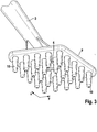
- the advanced nozzle-like structure according to the illustration Fig. 1 or 3 has an outlet opening 4, for example, a circular cross section, an oval cross-section or a slot-shaped cross-section according to the Fig. 2a to 2c can own.
- a first extension 7 is formed in the vicinity of the outlet opening 4 or located there.
- This first extension 7 forms, as it were, a spacer or a guide stop when the cartridge 1 is moved in the direction of the arrow Fig. 1 to the right.
- the second extension 8 which is formed substantially opposite the first extension, has a smaller longitudinal extent.
- the apparent in the figure distance between the lower end of the second extension 8 and the surface of the body 5 forms the maximum thickness of the fat layer 6.
- the order width can be varied and optimized.
- very wide slotted nozzles according to the invention lying, so that in a single application movement a very broad lubricant trace or lubricant layer can be generated.
- At least the second extension 8 may have some flexibility or may have a brush-like construction to enhance the spreading and adherence of the fat layer on the surface of the body 5.
- the body 3 may be formed as an integral part of the cartridge 1, but also designed as a separate, replaceable nozzle, in order then to use a customized, different nozzle for each application, without requiring a new, fat-filled cartridge along with an integral gland is.
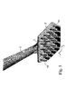
- the outlet opening 4 surrounding a plate-shaped structure 9 is provided, which has on the side with the opening 4 a plurality of frustoconical or truncated pyramid-like projections 10.
- the extensions 10 are arranged in rows in the x and y directions, in particular in rows of 5.
- the extensions 10 are at least in the x-direction offset from one another to be able to distribute uniformly on the surface to be treated from the opening 4 leaking grease.
- the extensions 10 are elastically executable to a certain extent to the distribution of the corresponding amount of grease on in the Fig. 3 optimize surface not shown.
- the structure of plate 9 with extensions 10 may be in the region of the opening 4, e.g. be connected by positive engagement with the body 3. It is also conceivable here, a one-piece production.
Landscapes
- Engineering & Computer Science (AREA)
- Mechanical Engineering (AREA)
- Coating Apparatus (AREA)
- Physics & Mathematics (AREA)
- Geometry (AREA)
Abstract
Description
Die Erfindung betrifft eine Vorrichtung zum dosierten Auftragen und Verteilen von hochviskosen Stoffen, wie Klebemitteln, Fetten, Wachsen oder dergleichen, wobei der Stoff in einer ein vorgegebenes Füllvolumen aufweisenden Kartusche befindlich oder in diese einbringbar ist und die Kartusche eine Eigenstabilität derart aufweist, dass der jeweilige Stoff mittels eines Stempels oder dergleichen Mittel, welches Bestandteil der Kartusche ist, über eine an der Kartusche befindliche Öffnung austreten kann, gemäß Oberbegriff des Anspruches 1.The invention relates to a device for the metered application and distribution of highly viscous substances, such as adhesives, fats, waxes or the like, wherein the substance in a predetermined filling volume cartridge is located or can be introduced into this and the cartridge has an intrinsic stability such that the respective Fabric by means of a stamp or the like means, which is part of the cartridge, can escape via an opening located on the cartridge, according to the preamble of claim 1.
Aus der
Derartige Kartuschen weisen üblicherweise einen hohlzylindrischen Körper auf, der an einem seiner Enden durch einen Boden verschlossen ist. Vorbekannte Kartuschen sind zur Verteilung mit sogenannten Verteilerpistolen bestimmt. Bei Fettkartuschen wird die gesamte Kartusche in eine rohrförmige zylindrische Vorrichtung eingebracht, die z.B. als Handhebelfettpresse zum Stand der Technik gehört. Ein federbelasteter Stempel dringt in das Innere der Kartusche ein und führt zu einer Vorkomprimierung der Fettfüllung. Ein hydraulischer Handhebelmechanismus baut Druck auf mit der Folge, dass über eine Austrittsöffnung mit angeschlossener Düse eine Schmierstelle z. B. eines Kraftfahrzeuges über einen Schmiernippel versorgt werden kann.Such cartridges usually have a hollow cylindrical body which is closed at one of its ends by a bottom. Previously known cartridges are intended for distribution with so-called distributor pistols. In grease cartridges, the entire cartridge is inserted into a tubular cylindrical device, which belongs to the prior art, for example, as a manual lever grease press. A spring-loaded stamp penetrates into the interior of the cartridge and leads to a pre-compression of the grease filling. A hydraulic Hand lever mechanism builds up pressure, with the result that via a discharge opening with connected nozzle a lubrication point z. B. a motor vehicle can be powered by a grease nipple.
Problematisch ist jedoch bei derartigen hydraulischen oder pneumatischen Fettpressen ein gewünschtes großflächiges Auftragen einer Fettschicht, z. B. bei der Versorgung eines Gleitlagers bei einer Blattfederanordnung. Hier ist der Einsatz händischer Hilfsmittel zum Verteilen eines aufgebrachten Schmierstoffes erforderlich.However, the problem with such hydraulic or pneumatic grease presses is a desired large-area application of a grease layer, eg. B. in the supply of a sliding bearing in a leaf spring assembly. Here, the use of manual tools for distributing an applied lubricant is required.
Zum Stand der Technik gehören darüber hinaus Fettkartuschen für Stoßpressen mit einem zylindrischen Fettbehälter und einem in diesem geführten, als Abschluss des hinteren Endes des Fettbehälters dienenden Folgekolbens, wobei ein vorderes Ende des Fettbehälters mit mindestens einem Hubbegrenzungsanschlag für den Folgekolben versehen ist, gemäß
Bei der Kartusche gemäß
Dieselbe Problematik tritt bei der Kartusche nach
Zum Stand der Technik gehören aber auch stabile Kunststoffkartuschen, z. B. zum Schließen von Fugen mittels eines Silikon- oder Acrylmaterials, das eine entsprechende Viskosität aufweist.However, the prior art also includes stable plastic cartridges, z. B. for closing joints by means of a silicone or acrylic material having a corresponding viscosity.
Derartige Kunststoffkartuschen sind seitig mit einer durchstoßbaren Schrauböffnung versehen, die wiederum eine längliche, in konischer Form ausgebildete Düse aufnimmt.Such plastic cartridges are provided on the side with a pierceable screw opening, which in turn receives an elongated, formed in a conical shape nozzle.
Im Bodenteil befindet sich ein beweglicher Einsatz, der über eine pistolenartige Vorrichtung zur Aufnahme der Kartusche so in die Kartusche hinein, d.h. zum düsenseitigen Ende bewegbar ist, dass Zug um Zug die in der Kartusche befindliche Füllung austritt.In the bottom part there is a movable insert which is inserted into the cartridge via a gun-like device for receiving the cartridge, i. is movable to the nozzle-side end that train to train the filling located in the cartridge exits.
Mit derartigen bekannten starren und stabilen Kartuschenkörpern wurden jedoch bisher lediglich die erwähnte Acryl- oder Silikonmaterialien zum Schließen von Fugen oder zu ähnlichen Abdichtzwecken angeboten.With such known rigid and stable cartridge bodies, however, only the mentioned acrylic or silicone materials have hitherto been offered for closing joints or for similar sealing purposes.
Es besteht jedoch ein Bedarf hingehend, auch übliche Fett-, Schmier- und Gleitmittel, aber auch z.B. Klebstoffe auf unterschiedlich geformte Körper aufzubringen, ohne dass ein unmittelbarer Kontakt z.B. der menschlichen Hand mit dem aufzutragenden Mittel stattfindet, wobei hierfür auf das Prinzip einer Kartusche mit integriertem beweglichem Druckstempel zurückgegriffen werden soll.However, there is a need for it, including conventional lubricants, lubricants and lubricants, but also e.g. Apply adhesives to differently shaped bodies without direct contact e.g. the human hand with the agent to be applied takes place, for which purpose the principle of a cartridge with integrated movable plunger should be used.
Aus dem Vorgenannten ist es daher Aufgabe der Erfindung, eine weiterentwickelte Vorrichtung zum dosierten Auftragen und Verteilen von hochviskosen Stoffen wie Klebemitteln, Fetten, Wachsen oder dergleichen anzugeben, wobei der Stoff in einer ein vorgegebenes Füllvolumen aufweisenden Kartusche befindlich oder in diese einbringbar ist. Eine Teilaufgabe der Erfindung besteht darin, ausgehend von an sich bekannten stabilen und starren Kartuschen mit integriertem Druckstempel diese Kartuschen so zu modifizieren, dass die erwähnten besonderen Stoffe auch großflächig, gleichmäßig und ohne händisches Zutun beim Verteilen des entsprechenden Stoffes auf beliebige flächige Körper aufbringbar sind.From the foregoing, it is therefore an object of the invention to provide a further developed device for the metered application and distribution of highly viscous substances such as adhesives, fats, waxes or the like, wherein the substance is located in a predetermined filling volume having a cartridge or can be introduced into this. A subtask of the invention is starting from known per se stable and rigid cartridges with integrated plunger to modify these cartridges so that the mentioned special substances can be applied over a large area, evenly and without manual intervention when distributing the corresponding substance on any two-dimensional body.
Die Lösung der Aufgabe der Erfindung erfolgt durch die Vorrichtung gemäß Anspruch 1, wobei die Unteransprüche mindestens zweckmäßige Ausgestaltungen und Weiterbildungen umfassen.The object of the invention is achieved by the device according to claim 1, wherein the dependent claims comprise at least expedient refinements and developments.
Es wird demnach von einer Vorrichtung zum dosierten Auftragen und Verteilen von hochviskosen Stoffen, wie Klebemitteln, Fetten, Wachsen oder dergleichen ausgegangen, wobei der Stoff in einer ein vorgegebenes Füllvolumen aufweisende Kartusche befindlich ist oder in diese eingebracht werden kann. Die Kartusche weist eine Eigenstabilität derart auf, dass der jeweilige Stoff mittels eines Stempels, welcher Bestandteil der Kartusche ist, über eine an der Kartusche befindliche Öffnung austreten kann.It is therefore of a device for the metered application and distribution of highly viscous substances, such as adhesives, fats, waxes or the like, wherein the substance is located in a predetermined filling volume having a cartridge or can be introduced into this. The cartridge has an intrinsic stability such that the respective substance can escape via an opening located on the cartridge by means of a punch which is part of the cartridge.
Erfindungsgemäß geht die Öffnung in ein im Vergleich zum Stand der Technik weiterentwickeltes düsenartiges Gebilde über oder ist mit einem solchen Gebilde verbindbar, wobei stoffaustragsseitig das Gebilde die eigentliche Düsen-Austrittsöffnung umgebende, beabstandete Fortsätze besitzt, um den austretenden Stoff hilfsmittelfrei auf einer an sich beliebigen Fläche zu verteilen.According to the invention, the opening merges into a nozzle-like structure which has been developed further in comparison with the prior art, wherein the structure on the substance discharge side has the projecting, spaced projections surrounding the actual nozzle outlet opening in order to free the exiting substance on an arbitrary surface to distribute.
Bei einer bevorzugten Ausführungsform der Erfindung bestehen die Fortsätze aus nachgiebigen, bürstenartigen Materialien.In a preferred embodiment of the invention, the extensions are made of compliant, brush-like materials.
Bevorzugt sind die Fortsätze an einer Erweiterung des düsenartigen Gebildes befindlich und wiederum bevorzugt als integraler Bestandteil des düsenartigen Gebildes ausgeführt.Preferably, the extensions are located on an extension of the nozzle-like structure and again preferably designed as an integral part of the nozzle-like structure.
Die Fortsätze weisen bei einer Ausführungsform der Erfindung einen seitlichen Abstand von der Düsenöffnung auf.The extensions have, in one embodiment of the invention, a lateral distance from the nozzle opening.
Ein Ergänzungsgedanke der Erfindung besteht darin, die Fortsätze mit einer unterschiedlichen Längsausdehnung zu versehen und/oder die Fortsätze in unterschiedlicher Querschnittsflächenform zu gestalten.A supplementary idea of the invention is to provide the extensions with a different longitudinal extent and / or to make the extensions in different cross-sectional surface shape.
Das düsenartige Gebilde kann lösbar an der Kartusche befestigt werden, um für den jeweiligen Applikationsfall angepasste unterschiedliche Düsen mit wiederum spezifizierten Fortsätzen zu verwenden.The nozzle-like structure can be detachably fastened to the cartridge in order to use different nozzles adapted to the respective application with again specified extensions.
Die Fortsätze können ring- oder kreisförmig um die eigentliche Austrittsöffnung angeordnet werden.The extensions can be arranged in a ring or in a circle around the actual outlet opening.
Eine Weiterbildung der Erfindung ist dadurch gekennzeichnet, dass mindestens ein Fortsatz als Abstandshalter beim Auftragen des jeweiligen hochviskosen Stoffes ausgebildet ist. Hierdurch ist sichergestellt, dass auch bei kompliziert geformten Oberflächen recht gleichmäßig eine Klebstoff-, Fett- oder Wachsschicht aufbringbar ist.A development of the invention is characterized in that at least one extension is formed as a spacer when applying the respective high-viscosity substance. This ensures that even with complicated shaped surfaces quite evenly an adhesive, grease or wax layer can be applied.
Die Erfindung soll nachstehend anhand eines Ausführungsbeispiels sowie unter Zuhilfenahme von Figuren näher erläutert werden.The invention will be explained below with reference to an embodiment and with the aid of figures.
Hierbei zeigen:
- Fig. 1
- eine Seitenansicht der erfindungsgemäßen Vorrichtung zum dosierten Auftragen und Verteilen von hochviskosen Stoffen;
- Fig. 2a bis 2c
- eine Draufsicht auf die Unterseite des düsenartigen Gebildes mit verschieden geformten Austrittsöffnungen und
- Fig. 3
- eine pespektivische Darstellung einer weiteren Ausführungsform der Erfindung.
- Fig. 1
- a side view of the device according to the invention for the metered application and distribution of highly viscous substances;
- Fig. 2a to 2c
- a plan view of the underside of the nozzle-like structure with differently shaped outlet openings and
- Fig. 3
- a perspective view of another embodiment of the invention.
Bei der Darstellung nach
Der Kartuschenkörper besteht aus einem stabilen Kunststoffmaterial und ist z.B. in seinem Inneren mit einer Fettfüllung versehen.The cartridge body is made of a sturdy plastic material and is e.g. provided in its interior with a grease filling.
Eine solche Kartusche wird in eine ebenfalls bekannte Hebel-Druckpistole (nicht gezeigt) eingesetzt. Die Hebel-Druckpistole wirkt auf einen im bzw. am Kartuschenboden fixierten, zur Innenseite hin beweglichen Stempel ein und übt Druck auf die Füllung derart aus, dass das Füllmaterial über eine Austrittsöffnung 2 mit nachgeordneter Düse ausgebracht werden kann.Such a cartridge is used in a likewise known lever pressure gun (not shown). The lever pressure gun acts on a fixed in or on the cartridge bottom, to the inside movable punch and exerts pressure on the filling in such a way that the filler material can be discharged through an outlet opening 2 with downstream nozzle.
Das weiterentwickelte düsenartige Gebilde gemäß der Darstellung nach
Zum Beschichten der Oberfläche eines Körpers 5, z.B. eines Gleitlagers, gilt es nun, eine definierte Fettschicht 6 aufzutragen, und zwar ohne dass z.B. mit einem Finger, einem Holzspat oder einem ähnlichen Mittel ein Fettklumpen verteilt wird.For coating the surface of a body 5, for example a sliding bearing, it is now necessary to apply a defined layer of
Hierfür wird die vorgestellte Lösung genutzt.For this purpose, the presented solution is used.
Gemäß der Seitenansicht nach
Der zweite Fortsatz 8, der im Wesentlichen dem ersten Fortsatz gegenüberliegend ausgebildet ist, weist eine geringere Längsausdehnung auf. Der in der Figur ersichtliche Abstand zwischen dem unteren Ende des zweiten Fortsatzes 8 und der Oberfläche des Körpers 5 bildet die maximale Dicke der Fettschicht 6. Beim Bewegen der Kartusche 1 in Pfeilrichtung und gleichzeitiger Druckausübung auf die Fettfüllung tritt eine entsprechende Fettmenge aus und kann in der gewünschten Schichtstärke auf den Körper 5 verbracht werden.The
Über die Varianz der Austrittsöffnungen gemäß den
Mindestens der zweite Fortsatz 8 kann eine gewisse Flexibilität besitzen oder einen bürstenartigen Aufbau aufweisen, um das Verteilen und Anhaften der Fettschicht auf der Oberfläche des Körpers 5 zu verbessern.At least the
Der Körper 3 kann als integraler Bestandteil der Kartusche 1 ausgebildet sein, aber auch als separate, auswechselbare Düse gestaltet werden, um dann für den jeweiligen Applikationsfall eine angepasste, unterschiedliche Düse einsetzen zu können, ohne dass jeweils eine neue, fettgefüllte Kartusche nebst integraler Drüse erforderlich ist.The
Für das Verbinden des düsenartigen Gebildes 3 mit der Kartusche 1 sind Schraubgewinde, bajonettartige Verschlüsse oder aber auch ein Verschluss über eine konische Flächenpressung denkbar.For the connection of the nozzle-
Obwohl beim vorgestellten Ausführungsbeispiel unter Rückgriff auf die Figuren von einer Fettfüllung der Kartusche ausgegangen wird, sind auch andere Materialien und deren Verteilung, z.B. die Verteilung von Klebstoffen gemäß Erfindungsidee einsetzbar.Although it is assumed in the presented embodiment, with reference to the figures of a grease filling of the cartridge, other materials and their distribution, e.g. the distribution of adhesives according to the invention idea can be used.
Bei der Ausführungsform gemäß
Beim gezeigten Beispiel nach
Dabei sind die Fortsätze 10 mindestens in x-Richtung versetzt zueinander ausgeführt, um aus der Öffnung 4 austretendes Fett gleichmäßig auf der zu behandelnden Oberfläche verteilen zu können.In this case, the
Die Fortsätze 10 sind in einem gewissen Maße elastisch ausführbar, um die Verteilung der entsprechenden Fettmenge auf die in der
Das Gebilde aus Platte 9 mit Fortsätzen 10 kann im Bereich der Öffnung 4 z.B. durch Formschluss mit dem Körper 3 verbunden werden. Denkbar ist aber auch hier eine einstückige Fertigung.The structure of plate 9 with
Claims (8)
dadurch gekennzeichnet, dass
die Öffnung in ein düsenartiges Gebilde übergeht oder mit einem solchen Gebilde verbindbar ist, wobei stoffaustrittsseitig das Gebilde die eigentliche Austrittsöffnung umgebende, beabstandete Fortsätze besitzt, um den austretenden Stoff hilfsmittelfrei auf einer Fläche zu verteilen.Device for the metered application and distribution of highly viscous substances, such as adhesives, fats, waxes or the like, wherein the substance is located in a predetermined filling volume cartridge having or can be introduced into this and the cartridge has an intrinsic stability such that the respective substance by means of a punch , which is part of the cartridge, can escape via an opening located on the cartridge,
characterized in that
the opening merges into a nozzle-like structure or can be connected to such a structure, wherein the material outlet side, the structure has the actual outlet opening surrounding, spaced extensions to distribute the exiting agent tool-free on a surface.
dadurch gekennzeichnet, dass
die Fortsätze aus einem nachgiebigen, bürstenartigen Material bestehen.Device according to claim 1,
characterized in that
the extensions consist of a resilient, brush-like material.
dadurch gekennzeichnet, dass
die Fortsätze an einer Erweiterung des düsenartigen Gebildes befindlich, bevorzugt als integraler Bestandteil ausgeführt sind.Apparatus according to claim 1 or 2,
characterized in that
the extensions are located on an extension of the nozzle-like structure, preferably designed as an integral part.
dadurch gekennzeichnet, dass
die Fortsätze in einem seitlichen Abstand von der Düsenöffnung befindlich sind.Device according to one of the preceding claims,
characterized in that
the projections are located at a lateral distance from the nozzle opening.
dadurch gekennzeichnet, dass
die Fortsätze eine unterschiedliche Längenausdehnung und/oder eine unterschiedliche Querschnittsfläche besitzen.Device according to one of the preceding claims,
characterized in that
the extensions have a different longitudinal extent and / or a different cross-sectional area.
dadurch gekennzeichnet, dass
das düsenartige Gebilde lösbar an der Kartusche befestigt ist, um für den jeweiligen Applikationsfall angepasste unterschiedliche Düsen einsetzen zu können.Device according to one of the preceding claims,
characterized in that
the nozzle-like structure is releasably attached to the cartridge in order to use adapted for the particular application case different nozzles can.
dadurch gekennzeichnet, dass
die Fortsätze ring- oder kreisförmig um die eigentliche Austrittsöffnung angeordnet sind.Device according to one of the preceding claims,
characterized in that
the extensions ring or are arranged in a circle around the actual outlet opening.
dadurch gekennzeichnet, dass
mindestens ein Fortsatz als Abstandshalter für das Auftragen des jeweiligen hochviskosen Stoffes ausgebildet ist.Device according to one of the preceding claims,
characterized in that
at least one extension is formed as a spacer for the application of the respective high-viscosity substance.
Applications Claiming Priority (1)
| Application Number | Priority Date | Filing Date | Title |
|---|---|---|---|
| DE202010015980U DE202010015980U1 (en) | 2010-11-29 | 2010-11-29 | Device for the metered application and distribution of highly viscous substances |
Publications (2)
| Publication Number | Publication Date |
|---|---|
| EP2471402A1 true EP2471402A1 (en) | 2012-07-04 |
| EP2471402B1 EP2471402B1 (en) | 2013-09-18 |
Family
ID=43706030
Family Applications (1)
| Application Number | Title | Priority Date | Filing Date |
|---|---|---|---|
| EP11189914.2A Not-in-force EP2471402B1 (en) | 2010-11-29 | 2011-11-21 | Device for regulated coatings and distribution of highly viscous substances |
Country Status (2)
| Country | Link |
|---|---|
| EP (1) | EP2471402B1 (en) |
| DE (1) | DE202010015980U1 (en) |
Families Citing this family (2)
| Publication number | Priority date | Publication date | Assignee | Title |
|---|---|---|---|---|
| ITPR20120038A1 (en) * | 2012-06-18 | 2013-12-19 | Velo Karameto | DEVICE FOR SPREADING SAUCES ON HAMS, SHOULDERS OR OTHER CURED MEATS |
| DE102015121449A1 (en) | 2015-12-09 | 2017-06-14 | Ba Assembly & Turnkey Systems Gmbh | Verstreicheinheit |
Citations (8)
| Publication number | Priority date | Publication date | Assignee | Title |
|---|---|---|---|---|
| DE8224610U1 (en) | 1982-08-27 | 1982-12-09 | Hallbauer Metallwarenfabrik GmbH, 6806 Viernheim | Grease cartridge |
| EP0530121A1 (en) * | 1991-07-30 | 1993-03-03 | Laboratoires Asepta | Combined liquid applicator and massage device |
| EP0945368A1 (en) * | 1998-03-24 | 1999-09-29 | L'oreal | Dispensing and applying head for a product, particularly a haircare product and packaging unit provided with such a head |
| WO2000010423A1 (en) * | 1998-08-18 | 2000-03-02 | Arich Inc. | Applicator and dispensing device using same |
| DE69518307T2 (en) | 1995-03-16 | 2001-06-13 | Manufacture Bourguignonne De Plastiques, Sennecey Les Dijon | Cartridge with a breakable base for pasty products |
| JP2001322688A (en) * | 2000-05-15 | 2001-11-20 | Maruichi Valve Co Ltd | Aerosol container nozzle pressing structure |
| DE60104656T2 (en) | 2000-02-09 | 2005-08-25 | Manufacture Bourguignonne De Plastiques | SHAPED TUBULAR CARTRIDGE WITH CONTROLLED CANCELABLE OPENING |
| DE19818455B4 (en) | 1998-04-24 | 2008-02-14 | Helser, Klaus D. | cartridge |
-
2010
- 2010-11-29 DE DE202010015980U patent/DE202010015980U1/en not_active Expired - Lifetime
-
2011
- 2011-11-21 EP EP11189914.2A patent/EP2471402B1/en not_active Not-in-force
Patent Citations (8)
| Publication number | Priority date | Publication date | Assignee | Title |
|---|---|---|---|---|
| DE8224610U1 (en) | 1982-08-27 | 1982-12-09 | Hallbauer Metallwarenfabrik GmbH, 6806 Viernheim | Grease cartridge |
| EP0530121A1 (en) * | 1991-07-30 | 1993-03-03 | Laboratoires Asepta | Combined liquid applicator and massage device |
| DE69518307T2 (en) | 1995-03-16 | 2001-06-13 | Manufacture Bourguignonne De Plastiques, Sennecey Les Dijon | Cartridge with a breakable base for pasty products |
| EP0945368A1 (en) * | 1998-03-24 | 1999-09-29 | L'oreal | Dispensing and applying head for a product, particularly a haircare product and packaging unit provided with such a head |
| DE19818455B4 (en) | 1998-04-24 | 2008-02-14 | Helser, Klaus D. | cartridge |
| WO2000010423A1 (en) * | 1998-08-18 | 2000-03-02 | Arich Inc. | Applicator and dispensing device using same |
| DE60104656T2 (en) | 2000-02-09 | 2005-08-25 | Manufacture Bourguignonne De Plastiques | SHAPED TUBULAR CARTRIDGE WITH CONTROLLED CANCELABLE OPENING |
| JP2001322688A (en) * | 2000-05-15 | 2001-11-20 | Maruichi Valve Co Ltd | Aerosol container nozzle pressing structure |
Also Published As
| Publication number | Publication date |
|---|---|
| DE202010015980U1 (en) | 2011-03-03 |
| EP2471402B1 (en) | 2013-09-18 |
Similar Documents
| Publication | Publication Date | Title |
|---|---|---|
| DE69807038T2 (en) | Packaging and application unit for a powdery, liquid or pasty product, which has a piston | |
| EP2470341B1 (en) | Method and device for applying a sealing compound to a surface | |
| DE102009034774A1 (en) | Application nozzle for viscous adhesives | |
| EP1782856B1 (en) | Dispenser for a liquid product | |
| WO2013135238A2 (en) | Set for processing a light-curing material | |
| DE102012109124A1 (en) | Dosing system, dosing process and manufacturing process | |
| DE102022103257A1 (en) | Integration of ejection needles with fluid ejection valve and method therefor | |
| EP2471402B1 (en) | Device for regulated coatings and distribution of highly viscous substances | |
| DE60127108T2 (en) | METHOD AND DEVICE FOR APPLYING VISCOSIVE OR PASTIVE MATERIAL TO A SUBSTRATE | |
| DE202005006547U1 (en) | Applicator for two or more components | |
| EP0139855A1 (en) | Device for intra-anal application of medicaments in liquid or pasty form | |
| DE102014202339B4 (en) | Spray head for applying and distributing liquids in minimal quantities | |
| DE1084469B (en) | Machine for applying adhesives, glues or the like to veneers, boards, paper, cardboard or the like. | |
| DE10000505C1 (en) | Silicone coating application on the inside of hollow cylinders using an inkjet printer head | |
| EP3037177A1 (en) | Device for the application of flowable material and multi-component cartridge | |
| DE19532920A1 (en) | Paper coating machine with simple means for precise breadthways dosing | |
| EP2443045B1 (en) | Multiple component cartridge with ventilation device | |
| EP0199925A2 (en) | Device for applying a primer to a profile or the like of plastic material | |
| DE3319197C2 (en) | Device in the manner of a marker pen, in particular for applying a viscous adhesive | |
| DE10258243B4 (en) | Device for applying a product to a support | |
| EP2734144B1 (en) | Application device for dental compositions | |
| DE102020000311B4 (en) | Device for storing and applying a free-flowing substance, in particular a cosmetic substance | |
| WO2023110569A1 (en) | Scraper and coating device | |
| DE20107072U1 (en) | Lower punch spray device for tabletting machines | |
| DE202023001075U1 (en) | Device for applying a technical fluid to a drive chain |
Legal Events
| Date | Code | Title | Description |
|---|---|---|---|
| AK | Designated contracting states |
Kind code of ref document: A1 Designated state(s): AL AT BE BG CH CY CZ DE DK EE ES FI FR GB GR HR HU IE IS IT LI LT LU LV MC MK MT NL NO PL PT RO RS SE SI SK SM TR |
|
| AX | Request for extension of the european patent |
Extension state: BA ME |
|
| PUAI | Public reference made under article 153(3) epc to a published international application that has entered the european phase |
Free format text: ORIGINAL CODE: 0009012 |
|
| 17P | Request for examination filed |
Effective date: 20120727 |
|
| RIC1 | Information provided on ipc code assigned before grant |
Ipc: B05C 17/005 20060101ALN20130306BHEP Ipc: B65D 83/28 20060101ALI20130306BHEP Ipc: A45D 24/22 20060101AFI20130306BHEP Ipc: A45D 40/26 20060101ALI20130306BHEP Ipc: B05C 17/01 20060101ALN20130306BHEP |
|
| GRAP | Despatch of communication of intention to grant a patent |
Free format text: ORIGINAL CODE: EPIDOSNIGR1 |
|
| RIC1 | Information provided on ipc code assigned before grant |
Ipc: A45D 24/22 20060101AFI20130314BHEP Ipc: B05C 17/01 20060101ALN20130314BHEP Ipc: B65D 83/28 20060101ALI20130314BHEP Ipc: A45D 40/26 20060101ALI20130314BHEP Ipc: B05C 17/005 20060101ALN20130314BHEP |
|
| RIC1 | Information provided on ipc code assigned before grant |
Ipc: A45D 40/26 20060101ALI20130403BHEP Ipc: A45D 24/22 20060101AFI20130403BHEP Ipc: B05C 17/005 20060101ALN20130403BHEP Ipc: B05C 17/01 20060101ALN20130403BHEP Ipc: B65D 83/28 20060101ALI20130403BHEP |
|
| INTG | Intention to grant announced |
Effective date: 20130418 |
|
| GRAS | Grant fee paid |
Free format text: ORIGINAL CODE: EPIDOSNIGR3 |
|
| GRAA | (expected) grant |
Free format text: ORIGINAL CODE: 0009210 |
|
| AK | Designated contracting states |
Kind code of ref document: B1 Designated state(s): AL AT BE BG CH CY CZ DE DK EE ES FI FR GB GR HR HU IE IS IT LI LT LU LV MC MK MT NL NO PL PT RO RS SE SI SK SM TR |
|
| REG | Reference to a national code |
Ref country code: GB Ref legal event code: FG4D Free format text: NOT ENGLISH |
|
| REG | Reference to a national code |
Ref country code: CH Ref legal event code: EP |
|
| REG | Reference to a national code |
Ref country code: IE Ref legal event code: FG4D Free format text: LANGUAGE OF EP DOCUMENT: GERMAN |
|
| REG | Reference to a national code |
Ref country code: AT Ref legal event code: REF Ref document number: 632273 Country of ref document: AT Kind code of ref document: T Effective date: 20131015 |
|
| REG | Reference to a national code |
Ref country code: DE Ref legal event code: R096 Ref document number: 502011001365 Country of ref document: DE Effective date: 20131107 |
|
| PG25 | Lapsed in a contracting state [announced via postgrant information from national office to epo] |
Ref country code: HR Free format text: LAPSE BECAUSE OF FAILURE TO SUBMIT A TRANSLATION OF THE DESCRIPTION OR TO PAY THE FEE WITHIN THE PRESCRIBED TIME-LIMIT Effective date: 20130918 Ref country code: NO Free format text: LAPSE BECAUSE OF FAILURE TO SUBMIT A TRANSLATION OF THE DESCRIPTION OR TO PAY THE FEE WITHIN THE PRESCRIBED TIME-LIMIT Effective date: 20131218 Ref country code: SE Free format text: LAPSE BECAUSE OF FAILURE TO SUBMIT A TRANSLATION OF THE DESCRIPTION OR TO PAY THE FEE WITHIN THE PRESCRIBED TIME-LIMIT Effective date: 20130918 Ref country code: CY Free format text: LAPSE BECAUSE OF FAILURE TO SUBMIT A TRANSLATION OF THE DESCRIPTION OR TO PAY THE FEE WITHIN THE PRESCRIBED TIME-LIMIT Effective date: 20130904 Ref country code: LT Free format text: LAPSE BECAUSE OF FAILURE TO SUBMIT A TRANSLATION OF THE DESCRIPTION OR TO PAY THE FEE WITHIN THE PRESCRIBED TIME-LIMIT Effective date: 20130918 |
|
| REG | Reference to a national code |
Ref country code: NL Ref legal event code: VDEP Effective date: 20130918 |
|
| REG | Reference to a national code |
Ref country code: LT Ref legal event code: MG4D |
|
| PG25 | Lapsed in a contracting state [announced via postgrant information from national office to epo] |
Ref country code: RS Free format text: LAPSE BECAUSE OF FAILURE TO SUBMIT A TRANSLATION OF THE DESCRIPTION OR TO PAY THE FEE WITHIN THE PRESCRIBED TIME-LIMIT Effective date: 20130918 Ref country code: GR Free format text: LAPSE BECAUSE OF FAILURE TO SUBMIT A TRANSLATION OF THE DESCRIPTION OR TO PAY THE FEE WITHIN THE PRESCRIBED TIME-LIMIT Effective date: 20131219 Ref country code: SI Free format text: LAPSE BECAUSE OF FAILURE TO SUBMIT A TRANSLATION OF THE DESCRIPTION OR TO PAY THE FEE WITHIN THE PRESCRIBED TIME-LIMIT Effective date: 20130918 Ref country code: FI Free format text: LAPSE BECAUSE OF FAILURE TO SUBMIT A TRANSLATION OF THE DESCRIPTION OR TO PAY THE FEE WITHIN THE PRESCRIBED TIME-LIMIT Effective date: 20130918 Ref country code: LV Free format text: LAPSE BECAUSE OF FAILURE TO SUBMIT A TRANSLATION OF THE DESCRIPTION OR TO PAY THE FEE WITHIN THE PRESCRIBED TIME-LIMIT Effective date: 20130918 |
|
| PG25 | Lapsed in a contracting state [announced via postgrant information from national office to epo] |
Ref country code: CY Free format text: LAPSE BECAUSE OF FAILURE TO SUBMIT A TRANSLATION OF THE DESCRIPTION OR TO PAY THE FEE WITHIN THE PRESCRIBED TIME-LIMIT Effective date: 20130918 |
|
| PG25 | Lapsed in a contracting state [announced via postgrant information from national office to epo] |
Ref country code: EE Free format text: LAPSE BECAUSE OF FAILURE TO SUBMIT A TRANSLATION OF THE DESCRIPTION OR TO PAY THE FEE WITHIN THE PRESCRIBED TIME-LIMIT Effective date: 20130918 Ref country code: CZ Free format text: LAPSE BECAUSE OF FAILURE TO SUBMIT A TRANSLATION OF THE DESCRIPTION OR TO PAY THE FEE WITHIN THE PRESCRIBED TIME-LIMIT Effective date: 20130918 Ref country code: NL Free format text: LAPSE BECAUSE OF FAILURE TO SUBMIT A TRANSLATION OF THE DESCRIPTION OR TO PAY THE FEE WITHIN THE PRESCRIBED TIME-LIMIT Effective date: 20130918 Ref country code: SK Free format text: LAPSE BECAUSE OF FAILURE TO SUBMIT A TRANSLATION OF THE DESCRIPTION OR TO PAY THE FEE WITHIN THE PRESCRIBED TIME-LIMIT Effective date: 20130918 Ref country code: IS Free format text: LAPSE BECAUSE OF FAILURE TO SUBMIT A TRANSLATION OF THE DESCRIPTION OR TO PAY THE FEE WITHIN THE PRESCRIBED TIME-LIMIT Effective date: 20140118 |
|
| PG25 | Lapsed in a contracting state [announced via postgrant information from national office to epo] |
Ref country code: ES Free format text: LAPSE BECAUSE OF FAILURE TO SUBMIT A TRANSLATION OF THE DESCRIPTION OR TO PAY THE FEE WITHIN THE PRESCRIBED TIME-LIMIT Effective date: 20130918 Ref country code: PL Free format text: LAPSE BECAUSE OF FAILURE TO SUBMIT A TRANSLATION OF THE DESCRIPTION OR TO PAY THE FEE WITHIN THE PRESCRIBED TIME-LIMIT Effective date: 20130918 |
|
| BERE | Be: lapsed |
Owner name: KONIG, CHRISTIAN Effective date: 20131130 |
|
| REG | Reference to a national code |
Ref country code: DE Ref legal event code: R097 Ref document number: 502011001365 Country of ref document: DE |
|
| PG25 | Lapsed in a contracting state [announced via postgrant information from national office to epo] |
Ref country code: PT Free format text: LAPSE BECAUSE OF FAILURE TO SUBMIT A TRANSLATION OF THE DESCRIPTION OR TO PAY THE FEE WITHIN THE PRESCRIBED TIME-LIMIT Effective date: 20140120 |
|
| PLBE | No opposition filed within time limit |
Free format text: ORIGINAL CODE: 0009261 |
|
| STAA | Information on the status of an ep patent application or granted ep patent |
Free format text: STATUS: NO OPPOSITION FILED WITHIN TIME LIMIT |
|
| PG25 | Lapsed in a contracting state [announced via postgrant information from national office to epo] |
Ref country code: MC Free format text: LAPSE BECAUSE OF FAILURE TO SUBMIT A TRANSLATION OF THE DESCRIPTION OR TO PAY THE FEE WITHIN THE PRESCRIBED TIME-LIMIT Effective date: 20130918 |
|
| REG | Reference to a national code |
Ref country code: FR Ref legal event code: ST Effective date: 20140731 |
|
| 26N | No opposition filed |
Effective date: 20140619 |
|
| REG | Reference to a national code |
Ref country code: IE Ref legal event code: MM4A |
|
| PG25 | Lapsed in a contracting state [announced via postgrant information from national office to epo] |
Ref country code: IT Free format text: LAPSE BECAUSE OF FAILURE TO SUBMIT A TRANSLATION OF THE DESCRIPTION OR TO PAY THE FEE WITHIN THE PRESCRIBED TIME-LIMIT Effective date: 20130918 |
|
| PG25 | Lapsed in a contracting state [announced via postgrant information from national office to epo] |
Ref country code: DK Free format text: LAPSE BECAUSE OF FAILURE TO SUBMIT A TRANSLATION OF THE DESCRIPTION OR TO PAY THE FEE WITHIN THE PRESCRIBED TIME-LIMIT Effective date: 20130918 Ref country code: BE Free format text: LAPSE BECAUSE OF NON-PAYMENT OF DUE FEES Effective date: 20131130 |
|
| REG | Reference to a national code |
Ref country code: DE Ref legal event code: R097 Ref document number: 502011001365 Country of ref document: DE Effective date: 20140619 |
|
| PG25 | Lapsed in a contracting state [announced via postgrant information from national office to epo] |
Ref country code: IE Free format text: LAPSE BECAUSE OF NON-PAYMENT OF DUE FEES Effective date: 20131121 |
|
| PG25 | Lapsed in a contracting state [announced via postgrant information from national office to epo] |
Ref country code: FR Free format text: LAPSE BECAUSE OF NON-PAYMENT OF DUE FEES Effective date: 20131202 |
|
| PG25 | Lapsed in a contracting state [announced via postgrant information from national office to epo] |
Ref country code: RO Free format text: LAPSE BECAUSE OF FAILURE TO SUBMIT A TRANSLATION OF THE DESCRIPTION OR TO PAY THE FEE WITHIN THE PRESCRIBED TIME-LIMIT Effective date: 20130918 |
|
| PG25 | Lapsed in a contracting state [announced via postgrant information from national office to epo] |
Ref country code: SM Free format text: LAPSE BECAUSE OF FAILURE TO SUBMIT A TRANSLATION OF THE DESCRIPTION OR TO PAY THE FEE WITHIN THE PRESCRIBED TIME-LIMIT Effective date: 20130918 |
|
| REG | Reference to a national code |
Ref country code: CH Ref legal event code: PL |
|
| PG25 | Lapsed in a contracting state [announced via postgrant information from national office to epo] |
Ref country code: HU Free format text: LAPSE BECAUSE OF FAILURE TO SUBMIT A TRANSLATION OF THE DESCRIPTION OR TO PAY THE FEE WITHIN THE PRESCRIBED TIME-LIMIT; INVALID AB INITIO Effective date: 20111121 Ref country code: LU Free format text: LAPSE BECAUSE OF NON-PAYMENT OF DUE FEES Effective date: 20131121 Ref country code: LI Free format text: LAPSE BECAUSE OF NON-PAYMENT OF DUE FEES Effective date: 20141130 Ref country code: MK Free format text: LAPSE BECAUSE OF FAILURE TO SUBMIT A TRANSLATION OF THE DESCRIPTION OR TO PAY THE FEE WITHIN THE PRESCRIBED TIME-LIMIT Effective date: 20130918 Ref country code: BG Free format text: LAPSE BECAUSE OF FAILURE TO SUBMIT A TRANSLATION OF THE DESCRIPTION OR TO PAY THE FEE WITHIN THE PRESCRIBED TIME-LIMIT Effective date: 20130918 Ref country code: CH Free format text: LAPSE BECAUSE OF NON-PAYMENT OF DUE FEES Effective date: 20141130 |
|
| PG25 | Lapsed in a contracting state [announced via postgrant information from national office to epo] |
Ref country code: MT Free format text: LAPSE BECAUSE OF FAILURE TO SUBMIT A TRANSLATION OF THE DESCRIPTION OR TO PAY THE FEE WITHIN THE PRESCRIBED TIME-LIMIT Effective date: 20130918 |
|
| PGFP | Annual fee paid to national office [announced via postgrant information from national office to epo] |
Ref country code: DE Payment date: 20151229 Year of fee payment: 5 |
|
| GBPC | Gb: european patent ceased through non-payment of renewal fee |
Effective date: 20151121 |
|
| PG25 | Lapsed in a contracting state [announced via postgrant information from national office to epo] |
Ref country code: TR Free format text: LAPSE BECAUSE OF FAILURE TO SUBMIT A TRANSLATION OF THE DESCRIPTION OR TO PAY THE FEE WITHIN THE PRESCRIBED TIME-LIMIT Effective date: 20130918 |
|
| PG25 | Lapsed in a contracting state [announced via postgrant information from national office to epo] |
Ref country code: GB Free format text: LAPSE BECAUSE OF NON-PAYMENT OF DUE FEES Effective date: 20151121 |
|
| REG | Reference to a national code |
Ref country code: DE Ref legal event code: R119 Ref document number: 502011001365 Country of ref document: DE |
|
| PG25 | Lapsed in a contracting state [announced via postgrant information from national office to epo] |
Ref country code: DE Free format text: LAPSE BECAUSE OF NON-PAYMENT OF DUE FEES Effective date: 20170601 |
|
| REG | Reference to a national code |
Ref country code: AT Ref legal event code: MM01 Ref document number: 632273 Country of ref document: AT Kind code of ref document: T Effective date: 20161121 |
|
| PG25 | Lapsed in a contracting state [announced via postgrant information from national office to epo] |
Ref country code: AT Free format text: LAPSE BECAUSE OF NON-PAYMENT OF DUE FEES Effective date: 20161121 |
|
| PG25 | Lapsed in a contracting state [announced via postgrant information from national office to epo] |
Ref country code: AL Free format text: LAPSE BECAUSE OF FAILURE TO SUBMIT A TRANSLATION OF THE DESCRIPTION OR TO PAY THE FEE WITHIN THE PRESCRIBED TIME-LIMIT Effective date: 20130918 |