EP2471473A1 - Vorrichtung für laparoskopische Chirurgie - Google Patents
Vorrichtung für laparoskopische Chirurgie Download PDFInfo
- Publication number
- EP2471473A1 EP2471473A1 EP10382362A EP10382362A EP2471473A1 EP 2471473 A1 EP2471473 A1 EP 2471473A1 EP 10382362 A EP10382362 A EP 10382362A EP 10382362 A EP10382362 A EP 10382362A EP 2471473 A1 EP2471473 A1 EP 2471473A1
- Authority
- EP
- European Patent Office
- Prior art keywords
- pin
- trigger
- control
- ball joint
- rotation
- Prior art date
- Legal status (The legal status is an assumption and is not a legal conclusion. Google has not performed a legal analysis and makes no representation as to the accuracy of the status listed.)
- Withdrawn
Links
- 238000002357 laparoscopic surgery Methods 0.000 title claims abstract description 12
- 238000006073 displacement reaction Methods 0.000 claims description 17
- 230000005540 biological transmission Effects 0.000 claims description 12
- 238000000926 separation method Methods 0.000 claims 2
- 238000004873 anchoring Methods 0.000 claims 1
- 238000001356 surgical procedure Methods 0.000 abstract description 4
- 230000000694 effects Effects 0.000 abstract description 2
- 238000000034 method Methods 0.000 description 6
- 210000003811 finger Anatomy 0.000 description 5
- 206010049565 Muscle fatigue Diseases 0.000 description 3
- 230000008901 benefit Effects 0.000 description 3
- 238000002324 minimally invasive surgery Methods 0.000 description 3
- 230000036544 posture Effects 0.000 description 3
- 230000000284 resting effect Effects 0.000 description 3
- 210000001364 upper extremity Anatomy 0.000 description 3
- 230000009471 action Effects 0.000 description 2
- 230000001419 dependent effect Effects 0.000 description 2
- 230000007246 mechanism Effects 0.000 description 2
- 208000035824 paresthesia Diseases 0.000 description 2
- 230000002035 prolonged effect Effects 0.000 description 2
- 230000003068 static effect Effects 0.000 description 2
- 238000011477 surgical intervention Methods 0.000 description 2
- 230000007704 transition Effects 0.000 description 2
- 208000019914 Mental Fatigue Diseases 0.000 description 1
- 206010053156 Musculoskeletal discomfort Diseases 0.000 description 1
- 230000015271 coagulation Effects 0.000 description 1
- 238000005345 coagulation Methods 0.000 description 1
- 238000005056 compaction Methods 0.000 description 1
- 230000007812 deficiency Effects 0.000 description 1
- 230000010354 integration Effects 0.000 description 1
- 230000002262 irrigation Effects 0.000 description 1
- 238000003973 irrigation Methods 0.000 description 1
- 210000001503 joint Anatomy 0.000 description 1
- 210000003041 ligament Anatomy 0.000 description 1
- 210000003205 muscle Anatomy 0.000 description 1
- 230000002980 postoperative effect Effects 0.000 description 1
- 230000001144 postural effect Effects 0.000 description 1
- 238000011084 recovery Methods 0.000 description 1
- 230000003252 repetitive effect Effects 0.000 description 1
- 210000003813 thumb Anatomy 0.000 description 1
- 210000001519 tissue Anatomy 0.000 description 1
Images
Classifications
-
- A—HUMAN NECESSITIES
- A61—MEDICAL OR VETERINARY SCIENCE; HYGIENE
- A61B—DIAGNOSIS; SURGERY; IDENTIFICATION
- A61B17/00—Surgical instruments, devices or methods
- A61B17/28—Surgical forceps
- A61B17/29—Forceps for use in minimally invasive surgery
- A61B17/2909—Handles
-
- A—HUMAN NECESSITIES
- A61—MEDICAL OR VETERINARY SCIENCE; HYGIENE
- A61B—DIAGNOSIS; SURGERY; IDENTIFICATION
- A61B17/00—Surgical instruments, devices or methods
- A61B2017/0042—Surgical instruments, devices or methods with special provisions for gripping
- A61B2017/00424—Surgical instruments, devices or methods with special provisions for gripping ergonomic, e.g. fitting in fist
-
- A—HUMAN NECESSITIES
- A61—MEDICAL OR VETERINARY SCIENCE; HYGIENE
- A61B—DIAGNOSIS; SURGERY; IDENTIFICATION
- A61B17/00—Surgical instruments, devices or methods
- A61B17/28—Surgical forceps
- A61B17/29—Forceps for use in minimally invasive surgery
- A61B17/2909—Handles
- A61B2017/2912—Handles transmission of forces to actuating rod or piston
- A61B2017/2919—Handles transmission of forces to actuating rod or piston details of linkages or pivot points
- A61B2017/292—Handles transmission of forces to actuating rod or piston details of linkages or pivot points connection of actuating rod to handle, e.g. ball end in recess
-
- A—HUMAN NECESSITIES
- A61—MEDICAL OR VETERINARY SCIENCE; HYGIENE
- A61B—DIAGNOSIS; SURGERY; IDENTIFICATION
- A61B17/00—Surgical instruments, devices or methods
- A61B17/28—Surgical forceps
- A61B17/29—Forceps for use in minimally invasive surgery
- A61B17/2909—Handles
- A61B2017/2925—Pistol grips
-
- A—HUMAN NECESSITIES
- A61—MEDICAL OR VETERINARY SCIENCE; HYGIENE
- A61B—DIAGNOSIS; SURGERY; IDENTIFICATION
- A61B17/00—Surgical instruments, devices or methods
- A61B17/28—Surgical forceps
- A61B17/29—Forceps for use in minimally invasive surgery
- A61B2017/2926—Details of heads or jaws
- A61B2017/2927—Details of heads or jaws the angular position of the head being adjustable with respect to the shaft
- A61B2017/2929—Details of heads or jaws the angular position of the head being adjustable with respect to the shaft with a head rotatable about the longitudinal axis of the shaft
Definitions
- the present invention relates to an opening and closing surgical apparatus for laparoscopic surgery with ergonomic technical features which provide important improvements in the activity of surgeons performing this surgical technique minimally invasive.
- This ergonomic capacity is due to a particular form of actuating the opening and closing end tool.
- MIS Minimally invasive surgery
- the instruments differ not only in the function that they carry out but in the handle, length and design of the tip.
- Laparoscopic techniques and procedures, as well as the varieties of instruments have evolved in recent years, the appearance and operation thereof however continue to be similar to the initial designs.
- a common problem in the use of laparoscopic instruments is the size of the handle. Since surgical interventions are performed by surgeons of both sexes with different physical complexions and therefore with different hand sizes, the instruments require being able to be adapted to this characteristic of each professional.
- the size of the surgical glove helps to know the relationship between hand size and the grip of the handles. Larger sizes are common in men while smaller sizes are common in women. As a consequence, the women participating in the studies have more difficulties using laparoscopic instruments.
- PCT application number W02006/071121 discloses a mechanism formed by three linkages which transform the partial rotational movement of the trigger into a linear movement of the pin of the working shaft which opens and closes the distal tool. The latter remains open in the resting state due to the action of a spring.
- the present invention establishes an alternative pull mode, with minimal friction parts resulting in a very precise movement control and a much higher degree of compaction.
- the present invention is an apparatus for laparoscopic surgery which allows acting on an actuation tool.
- This actuation tool has rotating capacity and at least two degrees of opening. It is typical for it to incorporate a notched opening that can be opened up to a determined point and further maintain control over its angular position.
- the apparatus of the present invention comprises:
- an axial transmission part which in turn comprises a ball joint and a bar element, where the bar element is fixed angularly to the control with rotating capacity and the ball joint is fixed both angularly and axially to the end of the pin opposite the actuation tool; and, wherein the trigger comprises a head with a housing for the ball joint such that the pull of the trigger on the pin is exerted through the ball joint .
- axial transmission part which in turn comprises the following parts: a ball joint and a bar, is used.
- the axial transmission part is joined to the pin and acts on it, transmitting thereto two types of forces, torsional force to cause rotation and pull force to cause axial displacement.
- the attachment with the latter is such that it does not prevent the rotation imparted by the control.
- the control in turn acts on the bar such that the link between the bar and the control is such that the relative rotation therebetween is limited.
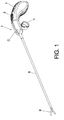
- Figure 1 shows an embodiment of the device (1) according to a perspective view which allows observing the outer elements.
- the device (1) has an actuation tool (9) at one end which serves to carry out the different actions inside the body to be operated on by means of laparoscopy.
- This actuation tool (9) according to this embodiment is a clamp with two degrees of freedom: rotation and opening and closing.
- the actuation tool (9) is located at the end of a tubular body (8) such that it has rotating capacity with respect to this tubular body (8).
- the base of the actuation tool (9) is integral with a pin (7) arranged inside the tubular body (8) and the pin is not seen in this figure.
- the rotation of the actuation tool (9) is achieved by means of the rotational movement of the pin (7); and, the opening or closing of the clamp is produced by the axial displacement of the pin (7) with respect to the tubular body (8) in which it is housed.
- the other end of the tubular body (8) is integral with the main body (C) of the device (1) where the main components allowing the actuation and control of the actuation tool (9) are located.
- the trigger (4) which opens and closes the actuation tool (9) which is actuated by means of the index finger of the user is located in the inner part of the main body (C).
- the same main body (C) is continuously prolonged in its rear part, becoming thicker until configuring the handle (2).
- a mainly conical and slightly dished sector of surface corresponding to the control (3) is observed in the transition between the main body (C) and the handle (2).
- This configuration and position of the control (3) allows exerting force with the thumb to either side, achieving its rotation and therefore also the rotation of the actuation tool (9). Since the surface in this transition between the main body (C) and the handle (2) has a curvature coinciding to a great extent with the curvature of the surface of the control (3) the degree of integration between both bodies is very high and allows very comfortable and effective handling.
- Figures 2 and 3 show a section of the main body (C) and the handle (2) to allow observing the parts contained therein, being shown with the trigger (4) in the resting position (in Figure 2 ) and with the trigger (4) actuated (in Figure 3 ).
- Both figures show how the pin (7) which is housed in the tubular body (8) is prolonged until reaching the inside of the main body (C).
- the pin (7) is aligned with the axis of rotation of the control (3), except for small deviations due to the operating mode.
- the rotation of the control (3) will cause the rotation of the pin (7) which in turn causes the rotation of the actuation tool (9).
- This movement is independent of the axial movement of the pin (7) which is responsible for opening and closing the actuation tool (9).
- the trigger (4) and the head (10) are two independent parts linked by a dovetail joint (4.1).
- This joint is secured by means of a clamp (6) entering holes (10.2) of the head (10) which communicate with other holes (4.1.1) in the dovetail (4.1) of the trigger (4).
- the head (10) has in the upper part two pivots (10.1) which, housed in respective slots of the main body (C), allow the rotation of the trigger (4) and the head (10), which move as a single body.
- the trigger (4) is interchangeable increases the range of possibilities of working triggers (4) which can be used with the same device not only for the index finger, but also for being able to work with one or more fingers positioned on said trigger (4).
- These interchangeable triggers (4) for example ring-shaped triggers, can be removed by the surgeon from the main body (C) at will according to his preferences.
- the head (10) is located below (the lower position is considered as below according to the orientation shown in the figure) the axis of rotation which the pivots (10.1) define. In this manner, upon pulling the trigger (4) towards the handle (2) by applying force with the index finger, the head (10) is also displaced backwards.
- the inside of the head (10) is partially hollow with two cylindrical surfaces (10.5) which allow housing a spherical body.
- This spherical body can be vertically displaced (also according to the position shown in this figure) sliding along the two cylindrical surfaces (10.5).
- a first groove (10.3) for the passage of the pin (7) is shown in the front part of the head (10).There is a second groove (10.4) for the passage of the part referred to as axial transmission part (5) in the rear part, in opposition to this first groove (10.3).
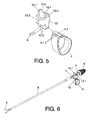
- the axial transmission part (5) can be observed in detail in Figure 7 where a ball joint (5.1) and a bar element (5.2) integral with one another are identified.
- the ball joint (5.1) is the spherical body which enters the housing of the head (10) formed between the cylindrical surfaces (10.5).
- Figure 7 also allows observing how the axial transmission part (5) in this embodiment is in turn made up of and formed by two halves trapping the end (7.1) of the pin (7).
- the end (7.1) of the pin (7) is curved and enters an internal housing (5.1.1) of one of the halves of the axial transmission part (5).
- This attachment makes two parts, the pin (7) and the axial transmission part (5), integral with one another. The rotation of one part causes the rotation of the other and the axial displacement of one part causes the axial displacement of the other.
- the bar element (5.2) has an outer polyhedral shape or any other shape which prevents the relative rotation with the control (3) which houses the end of the bar element (5.2).
- the section is a square section.
- the seat in the form of a cylindrical surface (10.5) and the spherical shape of the ball joint (5.1) allow transmitting the rotation imparted by the control (3) on the bar element (5.2) to the pin (7) completely independent of the axial position.
Landscapes
- Health & Medical Sciences (AREA)
- Surgery (AREA)
- Life Sciences & Earth Sciences (AREA)
- Biomedical Technology (AREA)
- Nuclear Medicine, Radiotherapy & Molecular Imaging (AREA)
- Engineering & Computer Science (AREA)
- Ophthalmology & Optometry (AREA)
- Heart & Thoracic Surgery (AREA)
- Medical Informatics (AREA)
- Molecular Biology (AREA)
- Animal Behavior & Ethology (AREA)
- General Health & Medical Sciences (AREA)
- Public Health (AREA)
- Veterinary Medicine (AREA)
- Surgical Instruments (AREA)
Priority Applications (1)
| Application Number | Priority Date | Filing Date | Title |
|---|---|---|---|
| EP10382362A EP2471473A1 (de) | 2010-12-29 | 2010-12-29 | Vorrichtung für laparoskopische Chirurgie |
Applications Claiming Priority (1)
| Application Number | Priority Date | Filing Date | Title |
|---|---|---|---|
| EP10382362A EP2471473A1 (de) | 2010-12-29 | 2010-12-29 | Vorrichtung für laparoskopische Chirurgie |
Publications (1)
| Publication Number | Publication Date |
|---|---|
| EP2471473A1 true EP2471473A1 (de) | 2012-07-04 |
Family
ID=44012339
Family Applications (1)
| Application Number | Title | Priority Date | Filing Date |
|---|---|---|---|
| EP10382362A Withdrawn EP2471473A1 (de) | 2010-12-29 | 2010-12-29 | Vorrichtung für laparoskopische Chirurgie |
Country Status (1)
| Country | Link |
|---|---|
| EP (1) | EP2471473A1 (de) |
Citations (8)
| Publication number | Priority date | Publication date | Assignee | Title |
|---|---|---|---|---|
| WO1995029641A1 (en) * | 1994-05-02 | 1995-11-09 | Baxter International Inc. | Laparoscopic surgical instrument |
| US5718714A (en) * | 1994-10-11 | 1998-02-17 | Circon Corporation | Surgical instrument with removable shaft assembly |
| US5810879A (en) * | 1997-02-27 | 1998-09-22 | Microline, Inc. | Laparoscopic instrument |
| WO1999003405A2 (en) * | 1997-07-16 | 1999-01-28 | Olympus Optical Co., Ltd. | Treatment tool for operation |
| US6595984B1 (en) * | 2000-03-28 | 2003-07-22 | Microline, Inc. | Laparoscopic instrument with a detachable tip |
| WO2006071120A1 (en) | 2004-12-29 | 2006-07-06 | Surgitech Norway As | An instrument, particularly for use in laparoscopic surgery |
| WO2006071121A1 (en) | 2004-12-29 | 2006-07-06 | Surgitech Norway As | An apparatus, particularly for use in laparoscopic surgery |
| EP2044893A2 (de) * | 2007-10-02 | 2009-04-08 | Tyco Healthcare Group LP | Chirurgisches Gelenk-Instrument |
-
2010
- 2010-12-29 EP EP10382362A patent/EP2471473A1/de not_active Withdrawn
Patent Citations (8)
| Publication number | Priority date | Publication date | Assignee | Title |
|---|---|---|---|---|
| WO1995029641A1 (en) * | 1994-05-02 | 1995-11-09 | Baxter International Inc. | Laparoscopic surgical instrument |
| US5718714A (en) * | 1994-10-11 | 1998-02-17 | Circon Corporation | Surgical instrument with removable shaft assembly |
| US5810879A (en) * | 1997-02-27 | 1998-09-22 | Microline, Inc. | Laparoscopic instrument |
| WO1999003405A2 (en) * | 1997-07-16 | 1999-01-28 | Olympus Optical Co., Ltd. | Treatment tool for operation |
| US6595984B1 (en) * | 2000-03-28 | 2003-07-22 | Microline, Inc. | Laparoscopic instrument with a detachable tip |
| WO2006071120A1 (en) | 2004-12-29 | 2006-07-06 | Surgitech Norway As | An instrument, particularly for use in laparoscopic surgery |
| WO2006071121A1 (en) | 2004-12-29 | 2006-07-06 | Surgitech Norway As | An apparatus, particularly for use in laparoscopic surgery |
| EP2044893A2 (de) * | 2007-10-02 | 2009-04-08 | Tyco Healthcare Group LP | Chirurgisches Gelenk-Instrument |
Similar Documents
| Publication | Publication Date | Title |
|---|---|---|
| US5893873A (en) | Surgical instrument having a handle with a removable, rotatable tip | |
| US8585734B2 (en) | Ergonomic handle and articulating laparoscopic tool | |
| US7648519B2 (en) | Surgical instrument | |
| US9968342B2 (en) | Handle for surgical instruments | |
| US20080255420A1 (en) | Surgical instrument | |
| EP3638136B1 (de) | Laparoskopische vorrichtungen | |
| WO2011024200A1 (en) | Laparoscopic apparatus | |
| KR20100110801A (ko) | 수술 기구 | |
| US20100004677A1 (en) | Shafted surgical instruments for remote access surgical procedures | |
| US11925344B2 (en) | Rotational driver | |
| EP3821832A1 (de) | Chirurgischer greifer | |
| US5827263A (en) | Surgical instrument handle | |
| US8683896B2 (en) | Ergonomic surgical instrument handle | |
| US10357268B2 (en) | Rotable and pivotable medical instrument | |
| EP2471473A1 (de) | Vorrichtung für laparoskopische Chirurgie | |
| US20120253364A1 (en) | Surgical Instrument Handle and Grip | |
| US11369397B2 (en) | Laparoscopic devices and methods of using | |
| CN219289602U (zh) | 仿生手术器械 | |
| CN217566218U (zh) | 仿生手术器械 | |
| WO2010002904A1 (en) | Shafted surgical instruments for remote access surgical procedures | |
| JP3922955B2 (ja) | 外科用処置具 | |
| JP7160377B2 (ja) | 鉗子 | |
| US5849021A (en) | Elongated thumb loop for surgical instrument | |
| JP2017176582A (ja) | 医療用鉗子 | |
| RU63207U1 (ru) | Хирургический инструмент |
Legal Events
| Date | Code | Title | Description |
|---|---|---|---|
| AK | Designated contracting states |
Kind code of ref document: A1 Designated state(s): AL AT BE BG CH CY CZ DE DK EE ES FI FR GB GR HR HU IE IS IT LI LT LU LV MC MK MT NL NO PL PT RO RS SE SI SK SM TR |
|
| AX | Request for extension of the european patent |
Extension state: BA ME |
|
| PUAI | Public reference made under article 153(3) epc to a published international application that has entered the european phase |
Free format text: ORIGINAL CODE: 0009012 |
|
| STAA | Information on the status of an ep patent application or granted ep patent |
Free format text: STATUS: THE APPLICATION IS DEEMED TO BE WITHDRAWN |
|
| 18D | Application deemed to be withdrawn |
Effective date: 20130105 |