EP2471626A2 - Verfahren und Vorrichtung zum Laserschweißen von Metallpfostenschäften - Google Patents
Verfahren und Vorrichtung zum Laserschweißen von Metallpfostenschäften Download PDFInfo
- Publication number
- EP2471626A2 EP2471626A2 EP11460040A EP11460040A EP2471626A2 EP 2471626 A2 EP2471626 A2 EP 2471626A2 EP 11460040 A EP11460040 A EP 11460040A EP 11460040 A EP11460040 A EP 11460040A EP 2471626 A2 EP2471626 A2 EP 2471626A2
- Authority
- EP
- European Patent Office
- Prior art keywords
- slit
- semi
- welding
- finished
- clamping
- Prior art date
- Legal status (The legal status is an assumption and is not a legal conclusion. Google has not performed a legal analysis and makes no representation as to the accuracy of the status listed.)
- Withdrawn
Links
Images



Classifications
-
- B—PERFORMING OPERATIONS; TRANSPORTING
- B23—MACHINE TOOLS; METAL-WORKING NOT OTHERWISE PROVIDED FOR
- B23K—SOLDERING OR UNSOLDERING; WELDING; CLADDING OR PLATING BY SOLDERING OR WELDING; CUTTING BY APPLYING HEAT LOCALLY, e.g. FLAME CUTTING; WORKING BY LASER BEAM
- B23K26/00—Working by laser beam, e.g. welding, cutting or boring
- B23K26/08—Devices involving relative movement between laser beam and workpiece
- B23K26/0869—Devices involving movement of the laser head in at least one axial direction
-
- B—PERFORMING OPERATIONS; TRANSPORTING
- B21—MECHANICAL METAL-WORKING WITHOUT ESSENTIALLY REMOVING MATERIAL; PUNCHING METAL
- B21C—MANUFACTURE OF METAL SHEETS, WIRE, RODS, TUBES, PROFILES OR LIKE SEMI-MANUFACTURED PRODUCTS OTHERWISE THAN BY ROLLING; AUXILIARY OPERATIONS USED IN CONNECTION WITH METAL-WORKING WITHOUT ESSENTIALLY REMOVING MATERIAL
- B21C37/00—Manufacture of metal sheets, rods, wire, tubes, profiles or like semi-manufactured products, not otherwise provided for; Manufacture of tubes of special shape
- B21C37/06—Manufacture of metal sheets, rods, wire, tubes, profiles or like semi-manufactured products, not otherwise provided for; Manufacture of tubes of special shape of tubes or metal hoses; Combined procedures for making tubes, e.g. for making multi-wall tubes
- B21C37/08—Making tubes with welded or soldered seams
- B21C37/0803—Making tubes with welded or soldered seams the tubes having a special shape, e.g. polygonal tubes
-
- B—PERFORMING OPERATIONS; TRANSPORTING
- B21—MECHANICAL METAL-WORKING WITHOUT ESSENTIALLY REMOVING MATERIAL; PUNCHING METAL
- B21C—MANUFACTURE OF METAL SHEETS, WIRE, RODS, TUBES, PROFILES OR LIKE SEMI-MANUFACTURED PRODUCTS OTHERWISE THAN BY ROLLING; AUXILIARY OPERATIONS USED IN CONNECTION WITH METAL-WORKING WITHOUT ESSENTIALLY REMOVING MATERIAL
- B21C37/00—Manufacture of metal sheets, rods, wire, tubes, profiles or like semi-manufactured products, not otherwise provided for; Manufacture of tubes of special shape
- B21C37/06—Manufacture of metal sheets, rods, wire, tubes, profiles or like semi-manufactured products, not otherwise provided for; Manufacture of tubes of special shape of tubes or metal hoses; Combined procedures for making tubes, e.g. for making multi-wall tubes
- B21C37/15—Making tubes of special shape; Making tube fittings
- B21C37/16—Making tubes with varying diameter in longitudinal direction
- B21C37/18—Making tubes with varying diameter in longitudinal direction conical tubes
-
- B—PERFORMING OPERATIONS; TRANSPORTING
- B23—MACHINE TOOLS; METAL-WORKING NOT OTHERWISE PROVIDED FOR
- B23K—SOLDERING OR UNSOLDERING; WELDING; CLADDING OR PLATING BY SOLDERING OR WELDING; CUTTING BY APPLYING HEAT LOCALLY, e.g. FLAME CUTTING; WORKING BY LASER BEAM
- B23K26/00—Working by laser beam, e.g. welding, cutting or boring
- B23K26/08—Devices involving relative movement between laser beam and workpiece
- B23K26/083—Devices involving movement of the workpiece in at least one axial direction
-
- B—PERFORMING OPERATIONS; TRANSPORTING
- B23—MACHINE TOOLS; METAL-WORKING NOT OTHERWISE PROVIDED FOR
- B23K—SOLDERING OR UNSOLDERING; WELDING; CLADDING OR PLATING BY SOLDERING OR WELDING; CUTTING BY APPLYING HEAT LOCALLY, e.g. FLAME CUTTING; WORKING BY LASER BEAM
- B23K26/00—Working by laser beam, e.g. welding, cutting or boring
- B23K26/20—Bonding
- B23K26/21—Bonding by welding
- B23K26/24—Seam welding
- B23K26/26—Seam welding of rectilinear seams
- B23K26/262—Seam welding of rectilinear seams of longitudinal seams of tubes
-
- B—PERFORMING OPERATIONS; TRANSPORTING
- B23—MACHINE TOOLS; METAL-WORKING NOT OTHERWISE PROVIDED FOR
- B23K—SOLDERING OR UNSOLDERING; WELDING; CLADDING OR PLATING BY SOLDERING OR WELDING; CUTTING BY APPLYING HEAT LOCALLY, e.g. FLAME CUTTING; WORKING BY LASER BEAM
- B23K37/00—Auxiliary devices or processes, not specially adapted for a procedure covered by only one of the other main groups of this subclass
- B23K37/02—Carriages for supporting the welding or cutting element
- B23K37/0211—Carriages for supporting the welding or cutting element travelling on a guide member, e.g. rail, track
- B23K37/0235—Carriages for supporting the welding or cutting element travelling on a guide member, e.g. rail, track the guide member forming part of a portal
-
- B—PERFORMING OPERATIONS; TRANSPORTING
- B23—MACHINE TOOLS; METAL-WORKING NOT OTHERWISE PROVIDED FOR
- B23K—SOLDERING OR UNSOLDERING; WELDING; CLADDING OR PLATING BY SOLDERING OR WELDING; CUTTING BY APPLYING HEAT LOCALLY, e.g. FLAME CUTTING; WORKING BY LASER BEAM
- B23K37/00—Auxiliary devices or processes, not specially adapted for a procedure covered by only one of the other main groups of this subclass
- B23K37/04—Auxiliary devices or processes, not specially adapted for a procedure covered by only one of the other main groups of this subclass for holding or positioning work
- B23K37/047—Auxiliary devices or processes, not specially adapted for a procedure covered by only one of the other main groups of this subclass for holding or positioning work moving work to adjust its position between soldering, welding or cutting steps
-
- B—PERFORMING OPERATIONS; TRANSPORTING
- B23—MACHINE TOOLS; METAL-WORKING NOT OTHERWISE PROVIDED FOR
- B23K—SOLDERING OR UNSOLDERING; WELDING; CLADDING OR PLATING BY SOLDERING OR WELDING; CUTTING BY APPLYING HEAT LOCALLY, e.g. FLAME CUTTING; WORKING BY LASER BEAM
- B23K2101/00—Articles made by soldering, welding or cutting
- B23K2101/04—Tubular or hollow articles
- B23K2101/06—Tubes
Definitions
- the subject of the invention is a method and a device for laser welding of metal post shafts constituting semi-finished products in the form of truncated cone or truncated polygonal pyramid with a slit existing along the whole length of the structures between edges of semi-finished product and created in the course of profiling them from sheet metal.
- Pole shafts welded this way are used for fabrication of lamp-posts, lighting and antenna masts, supporting structures for electric power transmission lines, and other structures for similar applications.
- Patent description from Polish patent application No. P-387779 reveals a method of fabrication of tapered cylindrical post by means of laser welding consisting in that the semi-finished post prepared earlier in the form of rounded off and not fully closed longitudinal element is subject to laser welding in the course of continuous process, within the whole thickness of the material, while the slit between joined edges of the semi-finished post is preferably kept in horizontal position, and the edges of the semi-finished product to be joined are pressed against each other by means of clamping elements distributed on both sides in the vicinity of the slit as well as on its opposite side.
- the slit welding device revealed in the above-quoted description is equipped with a welding laser acting on the slit situated in top horizontal position and clamping elements provided with rollers a part of which is situated on the opposite side of the welded slit and the other part is located in the vicinity of the slit and on both sides of it, where rollers of said clamping elements are connected to and co-operate with appropriate belt conveyors transporting the semi-finished post while its slit is being welded.
- trapezoid elements cut out from steel plate sheets representing shaft surface development have straight sides joined by means of laser welding method.
- a CO 2 laser head with power of 4-5 kW is used with continuous power control within 0,2-5 kW range, at wavelength of 10,6 nm and with pulse duration of 10 ⁇ s.
- the purpose of the present invention consists in provision of a method of laser welding of slits in semi-finished metal posts allowing to reduce significantly the cost of the process with simultaneous increase of productivity and possibility to obtain virtually uniform weld along the whole of its length. Further purpose of this invention consists in providing a simple and compact design of a device for laser welding allowing to level the slit to be welded very precisely thus improving significantly the quality of the produced welds. Unexpectedly, it was found in the course of tests and research work carried out in connection with this invention that one of its purposes consisting in increased productivity of welding process, improved weld parameters, failure-free operation and significantly reduced welding cost can be achieved by replacing CO 2 laser used previously for laser welding with fibre laser, main part of which is the active optical fibre in which laser radiation is generated.
- the principle of the metal post shaft welding method according to this invention consists in that after positioning the semi-finished product on rotating rollers of adjustable support beam of the welding machine, the pole shaft slit is levelled by means of said beam and blocked in this position by means of a side stop assembly, and then the semi-finished product is bilaterally and axially clamped in the horizontal plane from both sides by means of rack clamping assemblies, while at the same time the contacting edges are pressed by means of a hold-down roller moving over the slit in pace with the fibre laser head following the roller and welding together the slit edges along the whole length of semi-finished post shaft.
- the semi-finished product is kept in unchanged position, while the fibre laser head together with the clamping roller move along the welded slit with synchronised linear velocity, and positioning of the contacting edges creating the slit of semi-finished post shaft is achieved by means of forces acting in two mutually perpendicular planes.
- the contacting edges of the slit of semi-finished post shaft are pressed against each other by means of multiple pairs of clamping elements, preferably semicircular, situated opposite each other in horizontal axis of the semi-finished product, and by means of a sliding hold-down element, preferably of roller type, remaining in contact with the welded slit.
- the central idea of design of the device for welding slits in semi-finished metal post shafts with the use of fibre laser consists in that the body of the device represents a cuboidal frame supporting structure made of steel sections, upper part of which is equipped in horizontally located longitudinal beam, joined movably and slidably with a mobile clamping assembly, while both longitudinal and horizontally situated beams topping upper ends of lower vertical beams of the supporting structure are connected separably with rack-and-pinion clamping assemblies, clamping elements of which are situated opposite each other, in line with horizontal axis of the welded semi-finished post shaft and perpendicularly to vertical axis of the semi-finished product and the clamping roller, and moreover, opposite the upper beam and under the rack-and-pinion clamping assemblies, in line with their vertical symmetry axes, a support beam is situated horizontally and longitudinally, upper part of which is provided with support rollers connected rotationally with the beam, while both ends of the beam are equipped with two mechanisms fixing its horizontal position, and next to the body, on running rails
- Lower surface of the longitudinal beam is preferably provided with rolling guides in which the mobile clamping assembly is slidably mounted, with an outrigger terminated preferably with a revolving hold-down roller and equipped with a driving pneumatic actuator, while the support beam is equipped with revolving concave barrel-shaped support rollers distributed preferably along the whole of its length, and the mechanism supporting both ends of said beam represent supporting elements into which ends of bolts provided in knobs are screwed in with the other ends screwed into threaded holes provided in both ends of the beam.
- the rack-and-pinion clamping assemblies distributed preferably along the beam have identical construction and consists of a housing, covers of which are joined by means of screw bolts with profiled traction rollers mounted on them, and in axial seats of said covers there are two ball bearings mounted on axles with a pinion between them engaging two racks, profiled back sides of which constituting guides of the racks are in contact with angled lugs situated opposite each other, and racks of the rack-and-pinion clamping assemblies are provided with pneumatic actuators driving them. Ends of both lugs clamping the semi-finished post shaft along its horizontal axis of symmetry are preferably rounded.
- the welding device By equipping the welding device with a longitudinal beam connected rotationally with rotating rollers on which the welded semi-finished metal post shaft rests, with side mechanisms used for adjustment and precise levelling of the welded slit, and a side stop assembly blocking the shaft and thus also the levelled slit in the required position, it is possible to maintain control on levelling at different pole shaft convergence angles and diameters, thus ensuring perfect linearity in the course of the process of laser welding of the slits. Further, providing the device with a roller holding down edges of the slit eliminated entirely the possibility of relative displacement between edges of the welded slit.
- FIG. 1 presents schematically the device for welding metal post shafts, in the front view
- Fig. 2 the same device in the top view defined by direction of arrow "S”
- Fig. 3 the same device, in the side view
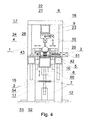
- Fig. 4 the same device, in vertical cross-section along line A-A of Fig. 1
- Fig. 5 the device's rack-and-pinion clamping assembly, in the side view
- Fig. 6 the same clamping assembly, in cross-section along line B-B
- Fig. 7 the same clamping assembly, in the side view defined by direction of arrow "W" of Fig. 5 ;
- Fig. 1 presents schematically the device for welding metal post shafts, in the front view
- Fig. 2 the same device in the top view defined by direction of arrow "S"
- Fig. 3 the same device, in the side view
- Fig. 4 the same device, in vertical cross-section along line A-A of Fig. 1
- Fig. 5 the device's rack-and-pinion
- FIG. 8 a simplified diagram of the device's rack-and-pinion clamping assemblies shown in Fig. 5 presenting the principle of its operation in the course of clamping of a semi-finished post shaft eliminating the slit remaining after the sheet metal forming process;
- Fig. 9 a fragment of the device with semi-finished post shaft positioned on rollers with the slit to be welded levelled, in the top view;
- Fig. 10 enlarged fragment "T" of the semi-finished product with a partial cross-section of its front face with tip of the stop assembly located in it.
- the device for laser welding of metal post shafts is composed of cuboidal frame supporting structure (1), lower part (2) of which is connected with rack-and-pinion clamping assemblies (3) of the welded post shaft (4), laying on concave barrel-shaped support rollers (5) attached rotationally to the assembly of support beam (6) situated longitudinally in line with symmetry axis of the supporting structure (1), while both ends of the beam are supported by means of mechanisms (7) attached to them and controlling horizontal position of welded slit of the post shaft (4), while the upper portion (8) of the supporting structure (1) is provided with immobile and horizontally situated beam (9), to which the mobile clamping assembly (10) is slidably attached, the beam (9) being situated coaxially with the supporting beam (6).
- the lower part (2) of the device's supporting structure (1) consists of four vertically situated supporting beams (11), (12), (13) and (14), of which upper ends of vertical beams (11) and (13) as well as beams (12) and (14) are topped with horizontal beams, the front (15) and the rear one (16), while the upper part (8) of the structure consists of another four vertical beams (17), (18), (19) and (20), situated on ends of horizontal beams (15) and (16), of which upper ends of beams (17 and 18) and (19 and 20) are topped with beams (21) and (22) situated transversally and horizontally, respectively, to which, at their half lengths, a longitudinally and horizontally situated beam (9) is welded on with mobile clamping assembly (10) mounted slidably to it.
- beam (9) is provided with two rolling guides (23) on its lower side, in which the mobile clamping assembly (10) is slidably mounted and provided with outrigger (24) terminated with a revolving hold-down roller (25) driven by means of pneumatic actuator (26) connected mechanically with said assembly and followed closely by the fibre laser header (27) of the welding device (28) mounted on rails (56) and equipped with a robot extension arm (57) of said laser head, longitudinal motion of which along the welded slit (29) in post shaft (4) is synchronised with translation motion of clamping roller (25) pressed against said slit.
- the lower part (2) of the device's supporting structure (1) is connected with the side stop assembly (32) equipped with a cylindrical-conical mandrel (33) positioning and maintaining in horizontal position the slit (29) of the pole shaft (4) by being located in the conical seat (58) of front wall (59) of said shaft before activation of the device's clamping assemblies (3).
- Each of the clamping assemblies (3) attached transversally to longitudinal beams (15) and (16) situated opposite each other and between rollers (5) supporting the pole shaft (4) has identical construction and consists of cuboidal housing (34) with two covers (35 and 36) joined by means of screw bolts (37).
- an axle (39) is mounted on which two ball bearings (38) are fastened as well as pinion (40), engaging two racks (41) and (42) situated opposite each other, back sides (43) of which, quasi-conical in shape, constituting guides for these racks, adhere to the two outermost profiled traction rollers (44) mounted on cylindrical portions (45) of screw bolts (37) and covered with side flat bars (46), attached to covers (35 and 36) of the housing (34).
- each of mechanisms (7) connected movably with ends of support beam (6) consists of a threaded support element (52), into which one end of bolt (53) is screwed, said bolt having knob (54) at its half length and the other end being screwed into a threaded hole (55) provided in offset (60) provided at the end of beam (6).
- the fundamental principle of the laser welding device consists in that a semi-finished post shaft (4) shaped from 2-6 mm thick sheet metal and 3-12 m long depending on what for it is intended, with a longitudinal slit (29) 5-10 mm wide depending on the shaft's diameter, is put, by means of a conveyor, onto rotating rollers (5) of the slit welding device.
- the semi-finished pole shaft (4) levelled and stabilised in this position is bilaterally clamped in horizontal plane and in its symmetry axis by means of many pairs of lugs (47) and (48) of clamping assemblies (3) distributed symmetrically between support rollers (5), resulting in pressing both edges (30 and 31) creating slit (29) against each other; then said edges, after elimination of said slit, are forced down from above by hold-down roller (25) of the mobile clamping assembly (10) situated perpendicularly to horizontal plane of clamping lugs (47 and 48).
- the pneumatic actuator (26) provides drive to the mobile clamping assembly (10), while the fibre laser head (27) mounted on the extension arm (57) of welding robot (28) located on rails (56) situated next to the device's supporting structure (1) follows said assembly in pace thus welding both edges (30 and 31) of the pole shaft (4) together.
Landscapes
- Engineering & Computer Science (AREA)
- Physics & Mathematics (AREA)
- Optics & Photonics (AREA)
- Mechanical Engineering (AREA)
- Plasma & Fusion (AREA)
- Laser Beam Processing (AREA)
Applications Claiming Priority (1)
| Application Number | Priority Date | Filing Date | Title |
|---|---|---|---|
| PL393489A PL216935B1 (pl) | 2010-12-30 | 2010-12-30 | Sposób i urządzenie do spawania laserowego trzonów słupów metalowych |
Publications (2)
| Publication Number | Publication Date |
|---|---|
| EP2471626A2 true EP2471626A2 (de) | 2012-07-04 |
| EP2471626A3 EP2471626A3 (de) | 2016-11-09 |
Family
ID=45558475
Family Applications (1)
| Application Number | Title | Priority Date | Filing Date |
|---|---|---|---|
| EP11460040.6A Withdrawn EP2471626A3 (de) | 2010-12-30 | 2011-07-28 | Verfahren und Vorrichtung zum Laserschweißen von Metallpfostenschäften |
Country Status (2)
| Country | Link |
|---|---|
| EP (1) | EP2471626A3 (de) |
| PL (1) | PL216935B1 (de) |
Cited By (13)
| Publication number | Priority date | Publication date | Assignee | Title |
|---|---|---|---|---|
| CN104588950A (zh) * | 2014-12-17 | 2015-05-06 | 常熟市华星精密铸件有限公司 | 一种焊接工装夹具 |
| CN107350807A (zh) * | 2017-07-06 | 2017-11-17 | 安徽悦众车身装备有限公司 | 汽车轮毂壳体焊接抛光喷漆装置 |
| CN108555517A (zh) * | 2018-07-18 | 2018-09-21 | 成都云奥智能科技有限公司 | 一种可双层定位夹紧的焊接撑涨夹具 |
| CN109128621A (zh) * | 2018-09-12 | 2019-01-04 | 刘道灵 | 一种基于灯具的智能制造设备 |
| CN112338393A (zh) * | 2020-10-27 | 2021-02-09 | 马鞍山市求是仪表厂 | 一种汽车仪表盘加工用焊接装置 |
| CN113523702A (zh) * | 2021-08-12 | 2021-10-22 | 杭州职业技术学院 | 一种金属异形件加工用的焊接夹具 |
| DE112017006843B4 (de) | 2017-01-16 | 2023-03-02 | Publichnoe Aktsionernoe Obshchestvo "Chelyabinskiy Truboprokatnyi Zavod" (Pao "Chtpz") | Fertigungs- und Schweißwerk zur Herstellung von Rohren |
| CN118455731A (zh) * | 2024-05-16 | 2024-08-09 | 江西艾芬达暖通科技股份有限公司 | 一种自动焊接机及用于毛巾架的焊接方法 |
| CN118699635A (zh) * | 2024-08-29 | 2024-09-27 | 江苏瀚彩光电科技有限公司 | 一种发光二极管生产用焊接装置 |
| CN119566541A (zh) * | 2024-12-19 | 2025-03-07 | 苏州思萃声光微纳技术研究所有限公司 | 一种用于金属表面的激光毛化处理装置 |
| CN119703572A (zh) * | 2025-01-20 | 2025-03-28 | 山东梁山华宇集团汽车制造有限公司 | 一种半挂车车厢生产加工用焊接装置 |
| CN119794716A (zh) * | 2025-02-21 | 2025-04-11 | 河北两山能源环保科技有限公司 | 一种钢管加工用焊接装置 |
| CN120791128A (zh) * | 2025-07-04 | 2025-10-17 | 江苏呈泰智慧科技有限公司 | 一种电路板激光焊接机 |
Families Citing this family (9)
| Publication number | Priority date | Publication date | Assignee | Title |
|---|---|---|---|---|
| CN108237302A (zh) * | 2018-01-31 | 2018-07-03 | 中国电子科技集团公司第三十八研究所 | 一种天线阵子的机器人点焊工装及方法 |
| CN108502481A (zh) * | 2018-05-25 | 2018-09-07 | 无锡市光彩机械制造有限公司 | 一种集成型钢模块用夹送机构 |
| CN108857229A (zh) * | 2018-08-02 | 2018-11-23 | 江苏安居模块化建筑有限公司 | 一种打包箱角柱组焊工装 |
| CN110369871A (zh) * | 2019-08-12 | 2019-10-25 | 湖南城市学院 | 一种管道加工用激光焊接装置 |
| CN110434486B (zh) * | 2019-08-21 | 2024-01-23 | 济南金威刻激光科技股份有限公司 | 一种带材多工位激光切割装置 |
| CN112780168B (zh) * | 2021-02-25 | 2022-11-25 | 新疆新铝铝业有限公司 | 一种铝合金防盗窗制作加工方法 |
| CN114043141B (zh) * | 2021-12-24 | 2024-06-21 | 福建骏鹏通信科技有限公司 | 一种用于储能柜高效全自动焊接工装 |
| CN114799699B (zh) * | 2022-05-26 | 2024-06-18 | 宜宾长盈精密技术有限公司 | 电池盖板极柱焊接工装 |
| CN115194384B (zh) * | 2022-07-29 | 2024-09-06 | 浙江中南绿建科技集团有限公司 | 一种波形钢板高质量拼接方法 |
Family Cites Families (2)
| Publication number | Priority date | Publication date | Assignee | Title |
|---|---|---|---|---|
| JPH06170588A (ja) * | 1992-11-30 | 1994-06-21 | Shinko Electric Co Ltd | テーパ管電弧熔接用治具 |
| WO2010111794A1 (de) * | 2009-04-03 | 2010-10-07 | Soutec Soudronic Ag | Verfahren und vorrichtung zur herstellung von rohrförmigen konischen metallteilen |
-
2010
- 2010-12-30 PL PL393489A patent/PL216935B1/pl unknown
-
2011
- 2011-07-28 EP EP11460040.6A patent/EP2471626A3/de not_active Withdrawn
Non-Patent Citations (1)
| Title |
|---|
| None |
Cited By (15)
| Publication number | Priority date | Publication date | Assignee | Title |
|---|---|---|---|---|
| CN104588950A (zh) * | 2014-12-17 | 2015-05-06 | 常熟市华星精密铸件有限公司 | 一种焊接工装夹具 |
| DE112017006843B4 (de) | 2017-01-16 | 2023-03-02 | Publichnoe Aktsionernoe Obshchestvo "Chelyabinskiy Truboprokatnyi Zavod" (Pao "Chtpz") | Fertigungs- und Schweißwerk zur Herstellung von Rohren |
| CN107350807A (zh) * | 2017-07-06 | 2017-11-17 | 安徽悦众车身装备有限公司 | 汽车轮毂壳体焊接抛光喷漆装置 |
| CN108555517A (zh) * | 2018-07-18 | 2018-09-21 | 成都云奥智能科技有限公司 | 一种可双层定位夹紧的焊接撑涨夹具 |
| CN108555517B (zh) * | 2018-07-18 | 2024-03-08 | 成都云奥智能科技有限公司 | 一种可双层定位夹紧的焊接撑涨夹具 |
| CN109128621A (zh) * | 2018-09-12 | 2019-01-04 | 刘道灵 | 一种基于灯具的智能制造设备 |
| CN112338393A (zh) * | 2020-10-27 | 2021-02-09 | 马鞍山市求是仪表厂 | 一种汽车仪表盘加工用焊接装置 |
| CN113523702B (zh) * | 2021-08-12 | 2022-12-06 | 杭州职业技术学院 | 一种金属异形件加工用的焊接夹具 |
| CN113523702A (zh) * | 2021-08-12 | 2021-10-22 | 杭州职业技术学院 | 一种金属异形件加工用的焊接夹具 |
| CN118455731A (zh) * | 2024-05-16 | 2024-08-09 | 江西艾芬达暖通科技股份有限公司 | 一种自动焊接机及用于毛巾架的焊接方法 |
| CN118699635A (zh) * | 2024-08-29 | 2024-09-27 | 江苏瀚彩光电科技有限公司 | 一种发光二极管生产用焊接装置 |
| CN119566541A (zh) * | 2024-12-19 | 2025-03-07 | 苏州思萃声光微纳技术研究所有限公司 | 一种用于金属表面的激光毛化处理装置 |
| CN119703572A (zh) * | 2025-01-20 | 2025-03-28 | 山东梁山华宇集团汽车制造有限公司 | 一种半挂车车厢生产加工用焊接装置 |
| CN119794716A (zh) * | 2025-02-21 | 2025-04-11 | 河北两山能源环保科技有限公司 | 一种钢管加工用焊接装置 |
| CN120791128A (zh) * | 2025-07-04 | 2025-10-17 | 江苏呈泰智慧科技有限公司 | 一种电路板激光焊接机 |
Also Published As
| Publication number | Publication date |
|---|---|
| PL393489A1 (pl) | 2012-07-02 |
| EP2471626A3 (de) | 2016-11-09 |
| PL216935B1 (pl) | 2014-05-30 |
Similar Documents
| Publication | Publication Date | Title |
|---|---|---|
| EP2471626A2 (de) | Verfahren und Vorrichtung zum Laserschweißen von Metallpfostenschäften | |
| JP2894761B2 (ja) | 木製構造体及びその製造用ローラープレス装置 | |
| DE10336032A1 (de) | Vorrichtung zum Schneiden oder Schweißen von rohrförmigen Werkstücken od. dgl. | |
| KR101712807B1 (ko) | 스테인레스 빔 제조장치 | |
| CN111890057A (zh) | 一种工字钢焊接加工系统 | |
| JP2020506804A (ja) | パイプの製造のための組み立て溶接ミル | |
| CN116038186B (zh) | 一种焊接生产线 | |
| CN209919127U (zh) | 导向装置 | |
| CN119703802A (zh) | 一种绿色建筑支撑梁焊接装置及其焊接方法 | |
| CN105215618A (zh) | 一种组对装置及利用该装置焊接的方法 | |
| US7378051B2 (en) | Method and apparatus for slitting steel slabs | |
| CN215509718U (zh) | 一种拼合辅助固定装置 | |
| CN115971773A (zh) | 一种锅炉钢结构板梁筋板焊接定位装置 | |
| CN118989685B (zh) | 一种多角度激光切割设备 | |
| CN213224498U (zh) | 轨道式板材切割机 | |
| JP5814943B2 (ja) | バンドを互いにそれらの縦縁に沿って接合するように案内するための装置及び方法 | |
| CN220636686U (zh) | 一种激光切割用夹具 | |
| DE3837911C2 (de) | ||
| CN207615854U (zh) | 用于生产弧形网片的焊网机 | |
| CN118081217A (zh) | 一种不锈钢件旋焊机 | |
| CN114799493B (zh) | 一种超快激光加工设备的自动对焦装置 | |
| CN214558260U (zh) | 激光连续焊接h型钢生产装置 | |
| CN214921725U (zh) | 一种用于焊接格栅钢架的装置 | |
| CN113210859A (zh) | 激光连续焊接h型钢生产装置 | |
| CN109277749B (zh) | 一种高精度激光对焊机的定位装置 |
Legal Events
| Date | Code | Title | Description |
|---|---|---|---|
| AK | Designated contracting states |
Kind code of ref document: A2 Designated state(s): AL AT BE BG CH CY CZ DE DK EE ES FI FR GB GR HR HU IE IS IT LI LT LU LV MC MK MT NL NO PL PT RO RS SE SI SK SM TR |
|
| AX | Request for extension of the european patent |
Extension state: BA ME |
|
| PUAI | Public reference made under article 153(3) epc to a published international application that has entered the european phase |
Free format text: ORIGINAL CODE: 0009012 |
|
| 17P | Request for examination filed |
Effective date: 20121207 |
|
| PUAL | Search report despatched |
Free format text: ORIGINAL CODE: 0009013 |
|
| AK | Designated contracting states |
Kind code of ref document: A3 Designated state(s): AL AT BE BG CH CY CZ DE DK EE ES FI FR GB GR HR HU IE IS IT LI LT LU LV MC MK MT NL NO PL PT RO RS SE SI SK SM TR |
|
| AX | Request for extension of the european patent |
Extension state: BA ME |
|
| RIC1 | Information provided on ipc code assigned before grant |
Ipc: B23K 37/047 20060101ALI20161004BHEP Ipc: B23K 101/06 20060101ALN20161004BHEP Ipc: B21C 37/08 20060101ALI20161004BHEP Ipc: B23K 37/02 20060101ALI20161004BHEP Ipc: B23K 26/26 20140101AFI20161004BHEP Ipc: B23K 26/08 20060101ALI20161004BHEP |
|
| RIC1 | Information provided on ipc code assigned before grant |
Ipc: B23K 37/047 20060101ALI20170505BHEP Ipc: B23K 37/02 20060101ALI20170505BHEP Ipc: B23K 26/08 20140101ALI20170505BHEP Ipc: B23K 101/06 20060101ALN20170505BHEP Ipc: B23K 26/26 20140101AFI20170505BHEP Ipc: B21C 37/08 20060101ALI20170505BHEP |
|
| RIC1 | Information provided on ipc code assigned before grant |
Ipc: B23K 37/02 20060101ALI20170515BHEP Ipc: B23K 37/047 20060101ALI20170515BHEP Ipc: B23K 26/26 20140101AFI20170515BHEP Ipc: B23K 101/06 20060101ALN20170515BHEP Ipc: B23K 26/08 20140101ALI20170515BHEP Ipc: B21C 37/08 20060101ALI20170515BHEP |
|
| GRAP | Despatch of communication of intention to grant a patent |
Free format text: ORIGINAL CODE: EPIDOSNIGR1 |
|
| RAP1 | Party data changed (applicant data changed or rights of an application transferred) |
Owner name: ELELEKTORMONTAZ RZESZOW |
|
| INTG | Intention to grant announced |
Effective date: 20170627 |
|
| STAA | Information on the status of an ep patent application or granted ep patent |
Free format text: STATUS: THE APPLICATION IS DEEMED TO BE WITHDRAWN |
|
| 18D | Application deemed to be withdrawn |
Effective date: 20171108 |