EP2471711A2 - Wasserrücklaufsystem - Google Patents
Wasserrücklaufsystem Download PDFInfo
- Publication number
- EP2471711A2 EP2471711A2 EP20120162457 EP12162457A EP2471711A2 EP 2471711 A2 EP2471711 A2 EP 2471711A2 EP 20120162457 EP20120162457 EP 20120162457 EP 12162457 A EP12162457 A EP 12162457A EP 2471711 A2 EP2471711 A2 EP 2471711A2
- Authority
- EP
- European Patent Office
- Prior art keywords
- water
- pump
- tank
- aircraft
- fuel
- Prior art date
- Legal status (The legal status is an assumption and is not a legal conclusion. Google has not performed a legal analysis and makes no representation as to the accuracy of the status listed.)
- Granted
Links
- XLYOFNOQVPJJNP-UHFFFAOYSA-N water Substances O XLYOFNOQVPJJNP-UHFFFAOYSA-N 0.000 title claims abstract description 126
- 230000002000 scavenging effect Effects 0.000 title claims abstract description 38
- 239000002828 fuel tank Substances 0.000 claims abstract description 48
- 238000000034 method Methods 0.000 claims abstract description 16
- 239000000446 fuel Substances 0.000 claims description 70
- 230000008878 coupling Effects 0.000 claims description 4
- 238000010168 coupling process Methods 0.000 claims description 4
- 238000005859 coupling reaction Methods 0.000 claims description 4
- 230000006698 induction Effects 0.000 description 5
- 238000005086 pumping Methods 0.000 description 4
- 238000010276 construction Methods 0.000 description 3
- 230000000694 effects Effects 0.000 description 3
- 238000011144 upstream manufacturing Methods 0.000 description 3
- 230000005484 gravity Effects 0.000 description 2
- 239000011295 pitch Substances 0.000 description 2
- 230000006835 compression Effects 0.000 description 1
- 238000007906 compression Methods 0.000 description 1
- 238000010586 diagram Methods 0.000 description 1
- 230000008014 freezing Effects 0.000 description 1
- 238000007710 freezing Methods 0.000 description 1
- 230000007257 malfunction Effects 0.000 description 1
- 238000012986 modification Methods 0.000 description 1
- 230000004048 modification Effects 0.000 description 1
Images


Classifications
-
- B—PERFORMING OPERATIONS; TRANSPORTING
- B64—AIRCRAFT; AVIATION; COSMONAUTICS
- B64D—EQUIPMENT FOR FITTING IN OR TO AIRCRAFT; FLIGHT SUITS; PARACHUTES; ARRANGEMENT OR MOUNTING OF POWER PLANTS OR PROPULSION TRANSMISSIONS IN AIRCRAFT
- B64D37/00—Arrangements in connection with fuel supply for power plant
- B64D37/34—Conditioning fuel, e.g. heating
-
- Y—GENERAL TAGGING OF NEW TECHNOLOGICAL DEVELOPMENTS; GENERAL TAGGING OF CROSS-SECTIONAL TECHNOLOGIES SPANNING OVER SEVERAL SECTIONS OF THE IPC; TECHNICAL SUBJECTS COVERED BY FORMER USPC CROSS-REFERENCE ART COLLECTIONS [XRACs] AND DIGESTS
- Y10—TECHNICAL SUBJECTS COVERED BY FORMER USPC
- Y10T—TECHNICAL SUBJECTS COVERED BY FORMER US CLASSIFICATION
- Y10T137/00—Fluid handling
- Y10T137/0318—Processes
- Y10T137/0324—With control of flow by a condition or characteristic of a fluid
- Y10T137/0329—Mixing of plural fluids of diverse characteristics or conditions
Definitions
- the present invention relates to a method and apparatus for removing water from a fuel tank.
- US4809934 describes a system for on-board disposal of water in aircraft fuel tanks. Water is drawn into a jet pump and dispersed into a fuel tank for consumption by the aircraft engines. A problem with the arrangement of US4809934 is that the water will only be fully removed when the fuel tank is empty. Also, the water dispersed in the fuel tank may create "snow" or cause icing in the tank at lower temperatures. Also, only a single fuel pump is provided, so there is no redundancy in the event of failure of the pump.
- a first aspect of the invention provides a fuel pumping and water scavenging system comprising: first and second fuel pumps each arranged to collect fuel from the same fuel tank and pump it towards an engine; and a water scavenging line coupling a water inlet in the fuel tank to the first pump, wherein the first pump is arranged to pump fuel towards the engine at a higher rate than the second pump, unless the first pump fails.
- a second aspect of the invention provides a method of removing water from a fuel tank using the system of the first aspect, the method comprising feeding water into the first pump with the water scavenging line; pumping fuel towards the engine with the first pump at a higher rate than the second pump; and pumping fuel towards the engine with the second pump at a higher rate than the first pump on failure of the first pump.
- the second pump provides an element of redundancy in the event of failure of the first pump. Arranging the first pump to pump fuel towards the engine at a higher rate than the second pump ensures that the second pump does not interfere with the water scavenging function of the first pump.
- first fuel pump further comprises a re-circulating outlet with a valve which closes at a first pressure
- second fuel pump further comprises a re-circulating outlet with a valve which closes at a second pressure which is lower than the first pressure
- the pumps have respective output lines which are coupled in parallel with each other, and the first fuel pump has a higher outlet pressure than the second fuel pump. Other techniques for achieving a similar result may be envisaged.
- the water may be injected into the first pump by an electrically powered pump.
- an electrically powered pump introduces the problem of routing electrical power cables into the fuel tank. Therefore preferably the water is injected into the first pump by means of a jet pump.
- the use of a j et pump (instead of an electrically powered pump) means that no additional electrical power is required, with attendant cables, control and safety aspects.
- the jet pump may be provided in a pump input line which couples a fuel inlet to the first pump, or in a re-circulating line which re-circulates fuel from an outlet of the first pump to an inlet of the first pump.
- a pump input line which couples a fuel inlet to the first pump
- a re-circulating line which re-circulates fuel from an outlet of the first pump to an inlet of the first pump.
- the rate of flow of water is proportional to the rate of flow of fuel in the pump input line, and as a result the concentration of water in the pump input line remains relatively constant regardless of the fuel flow rate.
- the latter case may be preferred in some cases since no constriction is required in the pump input line, and no additional construction is required in the pump input line.
- the jet pump may comprise a venturi constriction with the outlet of the water scavenging line positioned adjacent to the venturi constriction.
- the jet pump may comprise an induction tube.
- the first fuel pump may comprise a re-circulating output, and a re-circulating line coupling the re-circulating outlet to an inlet of the first pump.
- the re-circulating output can be used to "de-rate” the pump, and instead of opening into the fuel tank, the re-circulating output uses a re-circulating line to couple the flow back into the pump inlet. This ensures that water injected into the pump is not re-distributed into the fuel tank.
- the re-circulating output may also be used to provide the motive force for a jet pump, as described above.
- the method and system of the first and second aspect of the invention may be useful in an aircraft fuel tank, or any other kind of fuel tank in which water is prone to collect.
- the water scavenging line is arranged to collect water from one or more water inlets, the fuel tank has a region at the bottom of the tank where water pools during take off or climb, and at least one of the water inlets is located adjacent to the region so as to collect water during take off or climb.
- a third aspect of the invention provides a water scavenging system installed in an aircraft fuel tank and arranged to collect water from one or more water inlets and feed it into an engine of the aircraft, the fuel tank having a first region at the bottom of the tank where water pools during take off or climb, wherein at least one of the water inlets is located adjacent to the first region so as to collect water during take off or climb.
- a fourth aspect of the invention provides a method of removing water from an aircraft fuel tank, the method comprising collecting water from a pool at the bottom of the fuel tank during take off or climb and feeding the water to an engine of the aircraft.
- the fuel tank has a second region at the bottom of the tank where water pools when the aircraft is on the ground, and the system has no water inlets located adjacent to the second region.
- the first region is offset towards the rear of the fuel tank relative to the direction of travel of the aircraft.
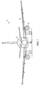
- an aircraft 1 comprises a fuselage 2 carrying a pair of wings, the left wing being labelled 3.
- Each wing carries an engine, the left hand engine being labelled 4 in Figure 1 .
- the engine includes a high pressure fuel pump (not shown) which requires a minimum inlet pressure, typically of the order of 5-10 psig.
- Fuel for each engine is stored in a centre tank and one or more wing tanks.
- a centre tank and one or more wing tanks.
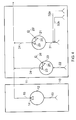
- Figure 2 is a schematic diagram showing the centre tank 10 and a wing tank 11 for the left hand wing 3.
- the centre tank 10 has an electrically driven fuel pump 12 with an input line 13 for collecting fuel from the tank 10, and an outlet 14 that incorporates a non return valve to prevent flow back into the pump, coupled in series to a fuel line 15 which leads to the engine 4.
- the wing tank 11 comprises a pair of electrically driven fuel pumps 20, 21 which are similar in construction (and are also similar to the fuel pump 12) so the same reference numerals will be used for equivalent parts.
- Each fuel pump 20, 21 comprises an input line 22,31 for collecting fuel from the tank, and a main outlet 23 which incorporates a non return valve to prevent flow back into the pump.
- the main outlet 23 is coupled in series to an output line 24.
- the output lines 24 are coupled in turn to the fuel line 15 in parallel with each other, and in parallel with the pump 12 in the centre tank 10.
- Each pump 20, 21 also has a re-circulating outlet 25 which is coupled to the inlet line 22,31 in parallel with the main outlet and non-return valve 23.
- the re-circulating outlet 25 leads to a pressure relief valve 26 that opens when the fuel pressure exceeds 24 psig.
- the valve 26 comprises a spring-loaded member which engages a valve seat and opens against the spring force when the pressure exceeds 24 psig.
- the pressure point at which the valve opens can be adjusted by adjusting the degree of compression of the spring.
- the valve 26 attached to the second pump 20 opens into the fuel tank, but the valve 26 attached to the first (water scavenging) pump 21 leads to a recirculation line 30 which re-circulates the flow back into the input line 31.
- the tanks are operated in sequence as follows.
- a problem with the re-circulating pump 20 is that any water fed into the pump will be atomised and redistributed into the wing tank 11 creating "snow" or causing icing in the tank at lower temperatures seen at altitude. Once the aircraft is at cruise altitude the external temperature is very low and the tank temperature will cool to less than the freezing point of water in approximately 30 minutes. After the water has frozen it is not possible to remove it from the tank until the aircraft thaws.
- a water scavenging line 32 shown in Figure 2 collects water from the sump of the wing tank 11 and injects it into the input line 31 of the pump 21.
- a recirculation duct 30 prevents this water being re-circulated into the wing tank 11, and potentially causing the "snow" or icing problems described above.
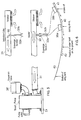
- the water scavenging system is shown in further detail in Figure 3 .
- the input line 31 has a fuel inlet 36 (incorporating a strainer) in the body of the fuel tank, and a jet pump comprising a venturi 33 which extends around the circumference of the pump input line.
- the venturi 33 is positioned upstream of the Y-connector junction 34 where the recirculation line 30 meets the inlet line 31.
- the water scavenging line 32 has an water inlet 35 at the sump of the fuel tank, and an outlet hole in the throat of the venturi 33. The low pressure at the throat of the venturi 33 sucks water from the water inlet 35 into the pump input line 31 and injects it into the main flow.
- the system By injecting the water into the pump input line 31 at a junction (that is, the outlet in the throat of the venturi 33) downstream of the fuel inlet 36, the system ensures that the water is delivered directly to the pump 21.
- the use of the venturi effect ensures that water is delivered at a rate proportional to the fuel flow through the pump input line.
- the venturi 33 is designed to only suck a significant amount of water at the high flows during take off and climb. As a result the water concentration is automatically limited to a level acceptable to the engine.
- the re-circulation line 30 prevents any water that is sucked up from being distributed back into the tank 11. Because the junction 34 is downstream of the venturi 33, the recirculation line 30 also limits the flow through the venturi 33 to the pump flow that leaves the wing tank. During take off and climb this is predominantly engine flow.
- the water scavenging system shown in Figures 3 is entirely automatic and powered by the hydraulic action of fuel in the inlet line 31. As a result no electrical power or data lines need to be routed into the fuel tank for the water scavenging system.
- the fuel system shown in Figures 4-6 address these problems.
- the fuel system shown in Figures 4-6 is similar to that shown in Figure 2 , and similar features are given the same reference numerals.
- the recirculation line 30 is omitted, and the sequence valve 26' on the first pump 21 re-circulates the fuel into the tank (similar to the sequence valve 26 on the second pump 20).
- the water scavenging system employs a pair of scavenging lines 32a,32b which are positioned side-by-side at the throat of the jet pump venturi 33 as shown in Figure 5 .
- the inlet 35a of the scavenging line 32a is positioned adjacent to the region 40, and the inlet 35b of the scavenging line 32b is positioned adjacent to the region 41. This ensures that water is only picked up during take off and climb, when the sequence valve 26' is closed. When the aircraft is on the ground, the sequence valve 26' is open (because the centre tank pump is delivering higher pressure fuel) but no water will be picked up and re-circulated into the tank. This is because there is no scavenging inlet adjacent to the region 42 where water tends to collect when the aircraft is on the ground.
- the pressure setting of the sequence valve 26' attached to the water scavenging pump 21 is set above that of the sequence valve 26 on the pump 20. This ensures that only the pump 21 will deliver fuel during take off and climb, unless that pump fails, in which case the pump 20 will take over.
- the sequence valves 26 in the system of Figure 2 also have such a differential pressure setting.
- the amount of water delivered to the engine is maximised. This is because the majority (between 70% and 95%) of the flow picked up by the pump 21 will be delivered to the engine, and only a small amount (between 5% and 30%) will be re-circulated into the tank. In contrast if both sequence valves 26,26' were open during take off and climb, then a smaller amount (between 35% and 46%) of the flow picked up by the pump 21 would be delivered to the engine, and the remainder (between 54% and 65%) would be re-circulated into the tank.
- FIG. 6 A variant of the jet pump interface between the water scavenging lines and the pump input line is shown in Figure 6 .
- the walls of the pump input line 31 are parallel (that is, there is no venturi) and the scavenging lines 32a,32b feed into an induction tube 50 which passes through the wall of the pump input line 31 and bends by 90° in the direction of flow.
- the induction tube 50 creates a constriction in the line 31 which results in a reduced pressure at the outlet of the tube 50. This reduced pressure draws the water from the induction tube 50 into the centre of the line 31 by the venturi effect.
- the centre tank 10 may have a water-scavenging system (not shown) of the kind described in US4809934 or of the kind described above with reference to Figures 4-6 (but without the re-circulation outlet).
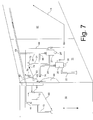
- Figure 7 is a plan view with the X-direction (that is, the direction of travel) of the aircraft pointing vertically down, in contrast to Figure 6 which is a side view with the X-direction (not shown) pointing horizontally to the left.
- a fuel scavenging system for the centre tank 10 is shown.
- the fuel scavenging system comprises a set of three scavenging inlets connected to a jet pump 61.
- the motive flow for the jet pump 61 is provided by a line 60 which branches out from the fuel line 15 and feeds the fuel back into the input line 13.
- the output lines 24 from the pumps 20,21 are coupled with each other in parallel at a junction 68 upstream of the junction 69 with the main fuel line.
- the lowest region when the aircraft is on the ground is indicated at 64 in Figure 7 .
- the aircraft pitches upwards at a steep angle so the pool of water moves back to a different region 65 which is offset towards the rear of the water tank 11 relative to the direction of travel X of the aircraft. This ensures that water is only picked up during take off and climb, when the sequence valve 26' is closed.
- the sequence valve 26' is open but no water will be picked up and re-circulated into the tank. This is because there is no scavenging inlet adjacent to the region 64 where water tends to collect when the aircraft is on the ground.
- a separate jet pump 70 is used with its motive flow being provided by a re-circulating line 66 which re-circulates fuel back into the input line 31. This means that no construction is required in the fuel input line 31.
- the outlet 74 of the re-circulating line 66 is in the fuel tank upstream of the fuel inlet 72, but is sufficiently adjacent to the fuel inlet 72 (and directed towards the fuel inlet 72) so that the majority of the flow from the re-circulating line 66 is picked up by the fuel inlet 72.
- the output of the re-circulating line 66 may be in the input line 31 downstream of the fuel inlet 72.
- a line 73 feeds fuel from both of the pumps 20,21 to an outer wing tank in order to provide motive flow for further fuel scavenging lines (not shown).
- a gravity feed line 74 feeds fuel towards the engine by the action of gravity in the event that both pumps 20 and 21 fail.
- the pumps 20, 21 are identical and have the same outlet pressure.
- the first pump 21 is configured to pump fuel towards the engine at a higher rate than the second pump 20 by setting its sequence valve with a higher pressure.
- the sequence valves 26,26' may be omitted completely, and the first pump 21 in this case is a larger pump with a higher outlet pressure than the second pump 20. This difference in outlet pressure has a similar effect to the differentially set sequence valves: that is, it ensures that little or no fuel will be fed towards the engine by the second pump 20, unless the first pump 21 fails.
Landscapes
- Engineering & Computer Science (AREA)
- Aviation & Aerospace Engineering (AREA)
- Cooling, Air Intake And Gas Exhaust, And Fuel Tank Arrangements In Propulsion Units (AREA)
- Structures Of Non-Positive Displacement Pumps (AREA)
- Jet Pumps And Other Pumps (AREA)
- Production Of Liquid Hydrocarbon Mixture For Refining Petroleum (AREA)
Applications Claiming Priority (2)
| Application Number | Priority Date | Filing Date | Title |
|---|---|---|---|
| GB0622564A GB0622564D0 (en) | 2006-11-13 | 2006-11-13 | Water scavenging system |
| EP20070824898 EP2086835B1 (de) | 2006-11-13 | 2007-11-12 | Wasserspülsystem |
Related Parent Applications (2)
| Application Number | Title | Priority Date | Filing Date |
|---|---|---|---|
| EP20070824898 Division EP2086835B1 (de) | 2006-11-13 | 2007-11-12 | Wasserspülsystem |
| EP07824898.6 Division | 2007-11-12 |
Publications (3)
| Publication Number | Publication Date |
|---|---|
| EP2471711A2 true EP2471711A2 (de) | 2012-07-04 |
| EP2471711A3 EP2471711A3 (de) | 2012-08-01 |
| EP2471711B1 EP2471711B1 (de) | 2014-09-17 |
Family
ID=37594802
Family Applications (2)
| Application Number | Title | Priority Date | Filing Date |
|---|---|---|---|
| EP20070824898 Not-in-force EP2086835B1 (de) | 2006-11-13 | 2007-11-12 | Wasserspülsystem |
| EP20120162457 Not-in-force EP2471711B1 (de) | 2006-11-13 | 2007-11-12 | Wasserrücklaufsystem |
Family Applications Before (1)
| Application Number | Title | Priority Date | Filing Date |
|---|---|---|---|
| EP20070824898 Not-in-force EP2086835B1 (de) | 2006-11-13 | 2007-11-12 | Wasserspülsystem |
Country Status (9)
| Country | Link |
|---|---|
| US (1) | US8840069B2 (de) |
| EP (2) | EP2086835B1 (de) |
| JP (2) | JP5184544B2 (de) |
| CN (1) | CN101535130B (de) |
| BR (1) | BRPI0718462A2 (de) |
| CA (1) | CA2667730C (de) |
| GB (1) | GB0622564D0 (de) |
| RU (1) | RU2446995C2 (de) |
| WO (1) | WO2008059288A1 (de) |
Families Citing this family (11)
| Publication number | Priority date | Publication date | Assignee | Title |
|---|---|---|---|---|
| GB0904171D0 (en) | 2009-03-11 | 2009-04-22 | Airbus Uk Ltd | Cyclonic separator |
| CN101870365B (zh) * | 2010-05-13 | 2013-04-10 | 哈尔滨飞机工业集团有限责任公司 | 飞机压力加油先导控制溢流系统 |
| CA2882491C (en) | 2012-08-22 | 2021-03-09 | Franklin Fueling Systems, Inc. | Method and apparatus for limiting acidic corrosion in fuel delivery systems |
| FR3056557B1 (fr) * | 2016-09-27 | 2018-12-07 | Airbus Operations Sas | Systeme d'alimentation en carburant pour un aeronef |
| US11365113B2 (en) | 2017-03-07 | 2022-06-21 | Franklin Fueling Systems, Llc | Method and apparatus for limiting acidic corrosion and contamination in fuel delivery systems |
| US11352248B2 (en) | 2017-03-07 | 2022-06-07 | Franklin Fueling Systems, Llc | Method and apparatus for limiting acidic corrosion and contamination in fuel delivery systems |
| WO2019094293A1 (en) | 2017-11-07 | 2019-05-16 | Cummins Filtration Ip, Inc. | Water drain mechanism for filter assemblies |
| FR3084056B1 (fr) * | 2018-07-17 | 2020-10-09 | Dassault Aviat | Ensemble de production d'energie et procede de purge de l'eau contenue dans un reservoir d'aeronef associe |
| FR3084055B1 (fr) * | 2018-07-17 | 2020-10-02 | Dassault Aviat | Systeme et necessaire de purge d'un reservoir et procedes de purge et de montage associes |
| US11485513B2 (en) * | 2018-10-05 | 2022-11-01 | Parker-Hannifin Corporation | Fuel pump override control method |
| FR3161609A1 (fr) * | 2024-04-30 | 2025-10-31 | Safran Aerosystems | Dispositif amélioré de récupération d’eau de réservoir de carburant d’aéronef |
Citations (1)
| Publication number | Priority date | Publication date | Assignee | Title |
|---|---|---|---|---|
| US4809934A (en) | 1987-02-12 | 1989-03-07 | British Aerospace Public Limited Company | On-board disposal of water in aircraft fuel tanks |
Family Cites Families (10)
| Publication number | Priority date | Publication date | Assignee | Title |
|---|---|---|---|---|
| GB8409999D0 (en) * | 1984-04-17 | 1984-05-31 | Plessey Co Plc | Fuel supply system |
| JPH0544177Y2 (de) * | 1987-04-27 | 1993-11-09 | ||
| DE4006216A1 (de) * | 1990-02-28 | 1991-09-05 | Mtu Friedrichshafen Gmbh | Vorrichtung zum ableiten von sich im behaelter eines wasserabscheiders einer brennkraftmaschine ansammelnden wassers |
| SU1839922A1 (ru) * | 1990-06-14 | 2006-06-20 | Открытое акционерное общество "Авиационный научно-технический комплекс им.А.Н.Туполева" | Система контроля газовой среды в топливных баках летательного аппарата |
| JP2678128B2 (ja) * | 1993-04-12 | 1997-11-17 | 松下精工株式会社 | 換気装置 |
| DE19646581A1 (de) * | 1996-11-12 | 1998-05-14 | Bosch Gmbh Robert | Kraftstoffeinspritzsystem |
| US6170470B1 (en) * | 1999-07-09 | 2001-01-09 | Brunswick Corporation | Fuel supply system for an internal combustion engine |
| GB0214273D0 (en) * | 2002-06-20 | 2002-07-31 | Boc Group Plc | Apparatus for controlling the pressure in a process chamber and method of operating same |
| US7114490B2 (en) * | 2004-09-24 | 2006-10-03 | Millennium Industries | Multiple pump fuel delivery system |
| US7234451B2 (en) * | 2005-07-27 | 2007-06-26 | Gm Global Technology Operations, Inc. | Dual fuel pump configuration for saddle fuel tanks |
-
2006
- 2006-11-13 GB GB0622564A patent/GB0622564D0/en not_active Ceased
-
2007
- 2007-11-12 EP EP20070824898 patent/EP2086835B1/de not_active Not-in-force
- 2007-11-12 RU RU2009119388/11A patent/RU2446995C2/ru not_active IP Right Cessation
- 2007-11-12 JP JP2009535818A patent/JP5184544B2/ja not_active Expired - Fee Related
- 2007-11-12 WO PCT/GB2007/050686 patent/WO2008059288A1/en not_active Ceased
- 2007-11-12 EP EP20120162457 patent/EP2471711B1/de not_active Not-in-force
- 2007-11-12 CA CA 2667730 patent/CA2667730C/en not_active Expired - Fee Related
- 2007-11-12 CN CN2007800420453A patent/CN101535130B/zh not_active Expired - Fee Related
- 2007-11-12 US US12/513,044 patent/US8840069B2/en not_active Expired - Fee Related
- 2007-11-12 BR BRPI0718462-0A2A patent/BRPI0718462A2/pt not_active IP Right Cessation
-
2013
- 2013-01-15 JP JP2013004805A patent/JP2013116737A/ja active Pending
Patent Citations (1)
| Publication number | Priority date | Publication date | Assignee | Title |
|---|---|---|---|---|
| US4809934A (en) | 1987-02-12 | 1989-03-07 | British Aerospace Public Limited Company | On-board disposal of water in aircraft fuel tanks |
Also Published As
| Publication number | Publication date |
|---|---|
| CA2667730C (en) | 2015-02-10 |
| CA2667730A1 (en) | 2008-05-22 |
| CN101535130A (zh) | 2009-09-16 |
| CN101535130B (zh) | 2013-03-13 |
| JP2010510421A (ja) | 2010-04-02 |
| EP2086835A1 (de) | 2009-08-12 |
| JP5184544B2 (ja) | 2013-04-17 |
| US20100071774A1 (en) | 2010-03-25 |
| US8840069B2 (en) | 2014-09-23 |
| EP2086835B1 (de) | 2012-06-27 |
| WO2008059288A1 (en) | 2008-05-22 |
| RU2009119388A (ru) | 2010-12-20 |
| GB0622564D0 (en) | 2006-12-20 |
| RU2446995C2 (ru) | 2012-04-10 |
| JP2013116737A (ja) | 2013-06-13 |
| EP2471711A3 (de) | 2012-08-01 |
| BRPI0718462A2 (pt) | 2013-12-03 |
| EP2471711B1 (de) | 2014-09-17 |
Similar Documents
| Publication | Publication Date | Title |
|---|---|---|
| CA2667730C (en) | Water scavenging system | |
| EP2099677B1 (de) | Wasserabfangsystem | |
| EP3412577B1 (de) | Kraftstoffzuführsystem | |
| EP3165466B1 (de) | Flugzeugkraftstoffsystem | |
| EP3077290B1 (de) | Blasenkollektor für ein kraftstoffansaugsystem | |
| US7588017B2 (en) | Low pressure jet by-pass system for fuel pump | |
| CN114954966B (zh) | 飞机供油和燃油转输系统及其方法 | |
| CN107128496A (zh) | 一种四发涡桨飞机供输油系统 | |
| CN120171777A (zh) | 飞机燃油应急放油系统 | |
| US3387644A (en) | Fuel vapor and air eductor system | |
| EP2117934B1 (de) | Wasserspülsystem | |
| EP3636477B1 (de) | Pumpeneinrichtung mit pumpe, verbrennungsmotor zum antrieb der pumpe und kraftstofftank | |
| JP2003226295A (ja) | 飛行機の燃料供給装置 | |
| CN116331499A (zh) | 一种无人机高可靠性输油系统 | |
| WO2001028853A1 (en) | An aircraft fuel system | |
| CN101580130A (zh) | 一种适应高空低温环境的飞机防冰燃油系统 | |
| CN120793183A (zh) | 一种飞行器空中供放油系统及方法 | |
| JP2004144076A (ja) | ディーゼルエンジンの燃料供給装置 |
Legal Events
| Date | Code | Title | Description |
|---|---|---|---|
| PUAL | Search report despatched |
Free format text: ORIGINAL CODE: 0009013 |
|
| AC | Divisional application: reference to earlier application |
Ref document number: 2086835 Country of ref document: EP Kind code of ref document: P |
|
| AK | Designated contracting states |
Kind code of ref document: A2 Designated state(s): AT BE BG CH CY CZ DE DK EE ES FI FR GB GR HU IE IS IT LI LT LU LV MC MT NL PL PT RO SE SI SK TR |
|
| PUAI | Public reference made under article 153(3) epc to a published international application that has entered the european phase |
Free format text: ORIGINAL CODE: 0009012 |
|
| AK | Designated contracting states |
Kind code of ref document: A3 Designated state(s): AT BE BG CH CY CZ DE DK EE ES FI FR GB GR HU IE IS IT LI LT LU LV MC MT NL PL PT RO SE SI SK TR |
|
| RIC1 | Information provided on ipc code assigned before grant |
Ipc: B64D 37/34 20060101AFI20120627BHEP |
|
| 17P | Request for examination filed |
Effective date: 20130129 |
|
| 17Q | First examination report despatched |
Effective date: 20130311 |
|
| GRAP | Despatch of communication of intention to grant a patent |
Free format text: ORIGINAL CODE: EPIDOSNIGR1 |
|
| INTG | Intention to grant announced |
Effective date: 20140410 |
|
| RIN1 | Information on inventor provided before grant (corrected) |
Inventor name: MINTY, ANDREW |
|
| GRAS | Grant fee paid |
Free format text: ORIGINAL CODE: EPIDOSNIGR3 |
|
| GRAA | (expected) grant |
Free format text: ORIGINAL CODE: 0009210 |
|
| AC | Divisional application: reference to earlier application |
Ref document number: 2086835 Country of ref document: EP Kind code of ref document: P |
|
| AK | Designated contracting states |
Kind code of ref document: B1 Designated state(s): AT BE BG CH CY CZ DE DK EE ES FI FR GB GR HU IE IS IT LI LT LU LV MC MT NL PL PT RO SE SI SK TR |
|
| REG | Reference to a national code |
Ref country code: GB Ref legal event code: FG4D |
|
| REG | Reference to a national code |
Ref country code: CH Ref legal event code: EP |
|
| REG | Reference to a national code |
Ref country code: IE Ref legal event code: FG4D |
|
| REG | Reference to a national code |
Ref country code: AT Ref legal event code: REF Ref document number: 687561 Country of ref document: AT Kind code of ref document: T Effective date: 20141015 |
|
| REG | Reference to a national code |
Ref country code: DE Ref legal event code: R096 Ref document number: 602007038633 Country of ref document: DE Effective date: 20141030 |
|
| PG25 | Lapsed in a contracting state [announced via postgrant information from national office to epo] |
Ref country code: SE Free format text: LAPSE BECAUSE OF FAILURE TO SUBMIT A TRANSLATION OF THE DESCRIPTION OR TO PAY THE FEE WITHIN THE PRESCRIBED TIME-LIMIT Effective date: 20140917 Ref country code: LT Free format text: LAPSE BECAUSE OF FAILURE TO SUBMIT A TRANSLATION OF THE DESCRIPTION OR TO PAY THE FEE WITHIN THE PRESCRIBED TIME-LIMIT Effective date: 20140917 Ref country code: FI Free format text: LAPSE BECAUSE OF FAILURE TO SUBMIT A TRANSLATION OF THE DESCRIPTION OR TO PAY THE FEE WITHIN THE PRESCRIBED TIME-LIMIT Effective date: 20140917 Ref country code: GR Free format text: LAPSE BECAUSE OF FAILURE TO SUBMIT A TRANSLATION OF THE DESCRIPTION OR TO PAY THE FEE WITHIN THE PRESCRIBED TIME-LIMIT Effective date: 20141218 |
|
| REG | Reference to a national code |
Ref country code: NL Ref legal event code: VDEP Effective date: 20140917 |
|
| REG | Reference to a national code |
Ref country code: LT Ref legal event code: MG4D |
|
| PG25 | Lapsed in a contracting state [announced via postgrant information from national office to epo] |
Ref country code: CY Free format text: LAPSE BECAUSE OF FAILURE TO SUBMIT A TRANSLATION OF THE DESCRIPTION OR TO PAY THE FEE WITHIN THE PRESCRIBED TIME-LIMIT Effective date: 20140917 Ref country code: LV Free format text: LAPSE BECAUSE OF FAILURE TO SUBMIT A TRANSLATION OF THE DESCRIPTION OR TO PAY THE FEE WITHIN THE PRESCRIBED TIME-LIMIT Effective date: 20140917 |
|
| REG | Reference to a national code |
Ref country code: AT Ref legal event code: MK05 Ref document number: 687561 Country of ref document: AT Kind code of ref document: T Effective date: 20140917 |
|
| PG25 | Lapsed in a contracting state [announced via postgrant information from national office to epo] |
Ref country code: NL Free format text: LAPSE BECAUSE OF FAILURE TO SUBMIT A TRANSLATION OF THE DESCRIPTION OR TO PAY THE FEE WITHIN THE PRESCRIBED TIME-LIMIT Effective date: 20140917 |
|
| PG25 | Lapsed in a contracting state [announced via postgrant information from national office to epo] |
Ref country code: SK Free format text: LAPSE BECAUSE OF FAILURE TO SUBMIT A TRANSLATION OF THE DESCRIPTION OR TO PAY THE FEE WITHIN THE PRESCRIBED TIME-LIMIT Effective date: 20140917 Ref country code: ES Free format text: LAPSE BECAUSE OF FAILURE TO SUBMIT A TRANSLATION OF THE DESCRIPTION OR TO PAY THE FEE WITHIN THE PRESCRIBED TIME-LIMIT Effective date: 20140917 Ref country code: CZ Free format text: LAPSE BECAUSE OF FAILURE TO SUBMIT A TRANSLATION OF THE DESCRIPTION OR TO PAY THE FEE WITHIN THE PRESCRIBED TIME-LIMIT Effective date: 20140917 Ref country code: PT Free format text: LAPSE BECAUSE OF FAILURE TO SUBMIT A TRANSLATION OF THE DESCRIPTION OR TO PAY THE FEE WITHIN THE PRESCRIBED TIME-LIMIT Effective date: 20150119 Ref country code: EE Free format text: LAPSE BECAUSE OF FAILURE TO SUBMIT A TRANSLATION OF THE DESCRIPTION OR TO PAY THE FEE WITHIN THE PRESCRIBED TIME-LIMIT Effective date: 20140917 Ref country code: IS Free format text: LAPSE BECAUSE OF FAILURE TO SUBMIT A TRANSLATION OF THE DESCRIPTION OR TO PAY THE FEE WITHIN THE PRESCRIBED TIME-LIMIT Effective date: 20150117 Ref country code: RO Free format text: LAPSE BECAUSE OF FAILURE TO SUBMIT A TRANSLATION OF THE DESCRIPTION OR TO PAY THE FEE WITHIN THE PRESCRIBED TIME-LIMIT Effective date: 20140917 |
|
| PG25 | Lapsed in a contracting state [announced via postgrant information from national office to epo] |
Ref country code: AT Free format text: LAPSE BECAUSE OF FAILURE TO SUBMIT A TRANSLATION OF THE DESCRIPTION OR TO PAY THE FEE WITHIN THE PRESCRIBED TIME-LIMIT Effective date: 20140917 Ref country code: PL Free format text: LAPSE BECAUSE OF FAILURE TO SUBMIT A TRANSLATION OF THE DESCRIPTION OR TO PAY THE FEE WITHIN THE PRESCRIBED TIME-LIMIT Effective date: 20140917 |
|
| REG | Reference to a national code |
Ref country code: DE Ref legal event code: R097 Ref document number: 602007038633 Country of ref document: DE |
|
| PG25 | Lapsed in a contracting state [announced via postgrant information from national office to epo] |
Ref country code: MC Free format text: LAPSE BECAUSE OF FAILURE TO SUBMIT A TRANSLATION OF THE DESCRIPTION OR TO PAY THE FEE WITHIN THE PRESCRIBED TIME-LIMIT Effective date: 20140917 Ref country code: BE Free format text: LAPSE BECAUSE OF NON-PAYMENT OF DUE FEES Effective date: 20141130 Ref country code: LU Free format text: LAPSE BECAUSE OF FAILURE TO SUBMIT A TRANSLATION OF THE DESCRIPTION OR TO PAY THE FEE WITHIN THE PRESCRIBED TIME-LIMIT Effective date: 20141112 |
|
| REG | Reference to a national code |
Ref country code: CH Ref legal event code: PL |
|
| PLBE | No opposition filed within time limit |
Free format text: ORIGINAL CODE: 0009261 |
|
| STAA | Information on the status of an ep patent application or granted ep patent |
Free format text: STATUS: NO OPPOSITION FILED WITHIN TIME LIMIT |
|
| PG25 | Lapsed in a contracting state [announced via postgrant information from national office to epo] |
Ref country code: LI Free format text: LAPSE BECAUSE OF NON-PAYMENT OF DUE FEES Effective date: 20141130 Ref country code: DK Free format text: LAPSE BECAUSE OF FAILURE TO SUBMIT A TRANSLATION OF THE DESCRIPTION OR TO PAY THE FEE WITHIN THE PRESCRIBED TIME-LIMIT Effective date: 20140917 Ref country code: CH Free format text: LAPSE BECAUSE OF NON-PAYMENT OF DUE FEES Effective date: 20141130 |
|
| 26N | No opposition filed |
Effective date: 20150618 |
|
| REG | Reference to a national code |
Ref country code: IE Ref legal event code: MM4A |
|
| PG25 | Lapsed in a contracting state [announced via postgrant information from national office to epo] |
Ref country code: IE Free format text: LAPSE BECAUSE OF NON-PAYMENT OF DUE FEES Effective date: 20141112 |
|
| REG | Reference to a national code |
Ref country code: FR Ref legal event code: PLFP Year of fee payment: 9 |
|
| PG25 | Lapsed in a contracting state [announced via postgrant information from national office to epo] |
Ref country code: SI Free format text: LAPSE BECAUSE OF FAILURE TO SUBMIT A TRANSLATION OF THE DESCRIPTION OR TO PAY THE FEE WITHIN THE PRESCRIBED TIME-LIMIT Effective date: 20140917 |
|
| PGFP | Annual fee paid to national office [announced via postgrant information from national office to epo] |
Ref country code: IT Payment date: 20151124 Year of fee payment: 9 |
|
| PG25 | Lapsed in a contracting state [announced via postgrant information from national office to epo] |
Ref country code: BG Free format text: LAPSE BECAUSE OF FAILURE TO SUBMIT A TRANSLATION OF THE DESCRIPTION OR TO PAY THE FEE WITHIN THE PRESCRIBED TIME-LIMIT Effective date: 20140917 |
|
| PG25 | Lapsed in a contracting state [announced via postgrant information from national office to epo] |
Ref country code: MT Free format text: LAPSE BECAUSE OF FAILURE TO SUBMIT A TRANSLATION OF THE DESCRIPTION OR TO PAY THE FEE WITHIN THE PRESCRIBED TIME-LIMIT Effective date: 20140917 Ref country code: TR Free format text: LAPSE BECAUSE OF FAILURE TO SUBMIT A TRANSLATION OF THE DESCRIPTION OR TO PAY THE FEE WITHIN THE PRESCRIBED TIME-LIMIT Effective date: 20140917 Ref country code: HU Free format text: LAPSE BECAUSE OF FAILURE TO SUBMIT A TRANSLATION OF THE DESCRIPTION OR TO PAY THE FEE WITHIN THE PRESCRIBED TIME-LIMIT; INVALID AB INITIO Effective date: 20071112 |
|
| REG | Reference to a national code |
Ref country code: FR Ref legal event code: PLFP Year of fee payment: 10 |
|
| PG25 | Lapsed in a contracting state [announced via postgrant information from national office to epo] |
Ref country code: IT Free format text: LAPSE BECAUSE OF NON-PAYMENT OF DUE FEES Effective date: 20161112 |
|
| REG | Reference to a national code |
Ref country code: FR Ref legal event code: PLFP Year of fee payment: 11 |
|
| PGFP | Annual fee paid to national office [announced via postgrant information from national office to epo] |
Ref country code: DE Payment date: 20191121 Year of fee payment: 13 |
|
| PGFP | Annual fee paid to national office [announced via postgrant information from national office to epo] |
Ref country code: FR Payment date: 20191120 Year of fee payment: 13 |
|
| PGFP | Annual fee paid to national office [announced via postgrant information from national office to epo] |
Ref country code: GB Payment date: 20191120 Year of fee payment: 13 |
|
| REG | Reference to a national code |
Ref country code: DE Ref legal event code: R119 Ref document number: 602007038633 Country of ref document: DE |
|
| GBPC | Gb: european patent ceased through non-payment of renewal fee |
Effective date: 20201112 |
|
| PG25 | Lapsed in a contracting state [announced via postgrant information from national office to epo] |
Ref country code: FR Free format text: LAPSE BECAUSE OF NON-PAYMENT OF DUE FEES Effective date: 20201130 |
|
| PG25 | Lapsed in a contracting state [announced via postgrant information from national office to epo] |
Ref country code: DE Free format text: LAPSE BECAUSE OF NON-PAYMENT OF DUE FEES Effective date: 20210601 Ref country code: GB Free format text: LAPSE BECAUSE OF NON-PAYMENT OF DUE FEES Effective date: 20201112 |