EP2471990B1 - Machine à laver - Google Patents
Machine à laver Download PDFInfo
- Publication number
- EP2471990B1 EP2471990B1 EP11195729.6A EP11195729A EP2471990B1 EP 2471990 B1 EP2471990 B1 EP 2471990B1 EP 11195729 A EP11195729 A EP 11195729A EP 2471990 B1 EP2471990 B1 EP 2471990B1
- Authority
- EP
- European Patent Office
- Prior art keywords
- circuit board
- board housing
- washing machine
- housing
- control unit
- Prior art date
- Legal status (The legal status is an assumption and is not a legal conclusion. Google has not performed a legal analysis and makes no representation as to the accuracy of the status listed.)
- Active
Links
Images


Classifications
-
- D—TEXTILES; PAPER
- D06—TREATMENT OF TEXTILES OR THE LIKE; LAUNDERING; FLEXIBLE MATERIALS NOT OTHERWISE PROVIDED FOR
- D06F—LAUNDERING, DRYING, IRONING, PRESSING OR FOLDING TEXTILE ARTICLES
- D06F34/00—Details of control systems for washing machines, washer-dryers or laundry dryers
- D06F34/28—Arrangements for program selection, e.g. control panels therefor; Arrangements for indicating program parameters, e.g. the selected program or its progress
- D06F34/34—Arrangements for program selection, e.g. control panels therefor; Arrangements for indicating program parameters, e.g. the selected program or its progress characterised by mounting or attachment features, e.g. detachable control panels or detachable display panels
-
- D—TEXTILES; PAPER
- D06—TREATMENT OF TEXTILES OR THE LIKE; LAUNDERING; FLEXIBLE MATERIALS NOT OTHERWISE PROVIDED FOR
- D06F—LAUNDERING, DRYING, IRONING, PRESSING OR FOLDING TEXTILE ARTICLES
- D06F34/00—Details of control systems for washing machines, washer-dryers or laundry dryers
- D06F34/28—Arrangements for program selection, e.g. control panels therefor; Arrangements for indicating program parameters, e.g. the selected program or its progress
- D06F34/32—Arrangements for program selection, e.g. control panels therefor; Arrangements for indicating program parameters, e.g. the selected program or its progress characterised by graphical features, e.g. touchscreens
-
- D—TEXTILES; PAPER
- D06—TREATMENT OF TEXTILES OR THE LIKE; LAUNDERING; FLEXIBLE MATERIALS NOT OTHERWISE PROVIDED FOR
- D06F—LAUNDERING, DRYING, IRONING, PRESSING OR FOLDING TEXTILE ARTICLES
- D06F33/00—Control of operations performed in washing machines or washer-dryers
- D06F33/30—Control of washing machines characterised by the purpose or target of the control
-
- D—TEXTILES; PAPER
- D06—TREATMENT OF TEXTILES OR THE LIKE; LAUNDERING; FLEXIBLE MATERIALS NOT OTHERWISE PROVIDED FOR
- D06F—LAUNDERING, DRYING, IRONING, PRESSING OR FOLDING TEXTILE ARTICLES
- D06F34/00—Details of control systems for washing machines, washer-dryers or laundry dryers
- D06F34/08—Control circuits or arrangements thereof
-
- D—TEXTILES; PAPER
- D06—TREATMENT OF TEXTILES OR THE LIKE; LAUNDERING; FLEXIBLE MATERIALS NOT OTHERWISE PROVIDED FOR
- D06F—LAUNDERING, DRYING, IRONING, PRESSING OR FOLDING TEXTILE ARTICLES
- D06F34/00—Details of control systems for washing machines, washer-dryers or laundry dryers
- D06F34/28—Arrangements for program selection, e.g. control panels therefor; Arrangements for indicating program parameters, e.g. the selected program or its progress
- D06F34/30—Arrangements for program selection, e.g. control panels therefor; Arrangements for indicating program parameters, e.g. the selected program or its progress characterised by mechanical features, e.g. buttons or rotary dials
-
- D—TEXTILES; PAPER
- D06—TREATMENT OF TEXTILES OR THE LIKE; LAUNDERING; FLEXIBLE MATERIALS NOT OTHERWISE PROVIDED FOR
- D06F—LAUNDERING, DRYING, IRONING, PRESSING OR FOLDING TEXTILE ARTICLES
- D06F37/00—Details specific to washing machines covered by groups D06F21/00 - D06F25/00
- D06F37/02—Rotary receptacles, e.g. drums
- D06F37/04—Rotary receptacles, e.g. drums adapted for rotation or oscillation about a horizontal or inclined axis
-
- H—ELECTRICITY
- H05—ELECTRIC TECHNIQUES NOT OTHERWISE PROVIDED FOR
- H05K—PRINTED CIRCUITS; CASINGS OR CONSTRUCTIONAL DETAILS OF ELECTRIC APPARATUS; MANUFACTURE OF ASSEMBLAGES OF ELECTRICAL COMPONENTS
- H05K5/00—Casings, cabinets or drawers for electric apparatus
- H05K5/0017—Casings, cabinets or drawers for electric apparatus with operator interface units
-
- D—TEXTILES; PAPER
- D06—TREATMENT OF TEXTILES OR THE LIKE; LAUNDERING; FLEXIBLE MATERIALS NOT OTHERWISE PROVIDED FOR
- D06F—LAUNDERING, DRYING, IRONING, PRESSING OR FOLDING TEXTILE ARTICLES
- D06F2101/00—User input for the control of domestic laundry washing machines, washer-dryers or laundry dryers
- D06F2101/20—Operation modes, e.g. delicate laundry washing programs, service modes or refreshment cycles
-
- D—TEXTILES; PAPER
- D06—TREATMENT OF TEXTILES OR THE LIKE; LAUNDERING; FLEXIBLE MATERIALS NOT OTHERWISE PROVIDED FOR
- D06F—LAUNDERING, DRYING, IRONING, PRESSING OR FOLDING TEXTILE ARTICLES
- D06F2105/00—Systems or parameters controlled or affected by the control systems of washing machines, washer-dryers or laundry dryers
- D06F2105/58—Indications or alarms to the control system or to the user
-
- D—TEXTILES; PAPER
- D06—TREATMENT OF TEXTILES OR THE LIKE; LAUNDERING; FLEXIBLE MATERIALS NOT OTHERWISE PROVIDED FOR
- D06F—LAUNDERING, DRYING, IRONING, PRESSING OR FOLDING TEXTILE ARTICLES
- D06F2105/00—Systems or parameters controlled or affected by the control systems of washing machines, washer-dryers or laundry dryers
- D06F2105/58—Indications or alarms to the control system or to the user
- D06F2105/60—Audible signals
-
- H—ELECTRICITY
- H05—ELECTRIC TECHNIQUES NOT OTHERWISE PROVIDED FOR
- H05K—PRINTED CIRCUITS; CASINGS OR CONSTRUCTIONAL DETAILS OF ELECTRIC APPARATUS; MANUFACTURE OF ASSEMBLAGES OF ELECTRICAL COMPONENTS
- H05K2201/00—Indexing scheme relating to printed circuits covered by H05K1/00
- H05K2201/10—Details of components or other objects attached to or integrated in a printed circuit board
- H05K2201/10007—Types of components
- H05K2201/10106—Light emitting diode [LED]
-
- Y—GENERAL TAGGING OF NEW TECHNOLOGICAL DEVELOPMENTS; GENERAL TAGGING OF CROSS-SECTIONAL TECHNOLOGIES SPANNING OVER SEVERAL SECTIONS OF THE IPC; TECHNICAL SUBJECTS COVERED BY FORMER USPC CROSS-REFERENCE ART COLLECTIONS [XRACs] AND DIGESTS
- Y02—TECHNOLOGIES OR APPLICATIONS FOR MITIGATION OR ADAPTATION AGAINST CLIMATE CHANGE
- Y02B—CLIMATE CHANGE MITIGATION TECHNOLOGIES RELATED TO BUILDINGS, e.g. HOUSING, HOUSE APPLIANCES OR RELATED END-USER APPLICATIONS
- Y02B40/00—Technologies aiming at improving the efficiency of home appliances, e.g. induction cooking or efficient technologies for refrigerators, freezers or dish washers
Definitions
- Embodiments of the present disclosure relate to a washing machine having a control panel.
- a washing machine includes a rotating tub in which laundry, such as clothes, etc., are accommodated, and a motor to drive the rotating tub.
- the washing machine performs a series of operations including washing, rinsing and dehydration using rotation of the rotating tub.
- a control panel is attached to a main body of the washing machine.
- the control panel is provided with a plurality of buttons to select operations of the washing machine and a display window to display operational modes of the washing machine.
- a circuit board is provided inside the control panel.
- the circuit board is provided with Light emitting elements, such as Light Emitting Diodes (LEDs), to display operational modes and switches connected to the buttons to control operations of the washing machine.
- LEDs Light Emitting Diodes
- a light guide member to guide light forward from the light emitting elements and a button support member to support the buttons are generally provided between the control panel and the circuit board.
- the light emitting elements and switches are mounted on a front surface of the circuit board within a housing having a front opening.
- An insulating material such as urethane, etc., is coated on the front surface of the circuit board to prevent transfer of heat when fire occurs on the circuit board.
- control panel consisting of a great number of elements has a complicated assembly process and high production costs.
- US 2005/183471 A1 disclose a printed circuit board and a corresponding display or control devices of a control panel, which are all integrated in the rearmost part of this control panel.
- US 2010/177494 A1 discloses a control panel assembly with a control panel, a guide member, and a circuit board. There is no particular housing for the circuit board.
- JP 2008/006046 A discloses a control panel frame and a number of other panels, such as PCB, without any further housings or also without a corresponding enclosure of a circuit board housing.
- EP 1 970 479 A1 discloses a control panel, according to which this is fixed to a transparent cover with plate-like devices therebetween.
- a washing machine includes a main body, and a control panel mounted to the main body, wherein the control panel includes a control panel frame assembled to the main body, a circuit board housing coupled to a rear side of the control panel frame and having an open rear side, and a circuit board accommodated in the circuit board housing, and wherein the circuit board is inserted into the circuit board housing through the open rear side of the circuit board housing such that a front surface thereof, on which light emitting elements to display operational modes of the washing machine are mounted, faces an inner wall surface of a front wall portion of the circuit board housing.
- the circuit board housing may include the front wall portion provided with a light guide to guide light emitted from the light emitting elements forward, a sidewall portion angled rearward from an edge of the front wall portion, and a circuit board mounting space defined by the front wall portion and the sidewall portion.
- the inner wall surface of the front wall portion of the circuit board housing may support the front surface of the circuit board.
- the circuit board housing may further include a button mount provided at the front wall portion thereof to support a button by which user button input pressure is applied.
- the circuit board housing may be made of fire-retardant plastic.
- the washing machine may further include a display panel coupled to the control panel frame to transmit light emitted from the light emitting elements.
- the control panel may further include a main control unit to supply power to the circuit board and control operation of the light emitting elements of the circuit board, and the main control unit may be coupled to the circuit board housing to shield at least a part of the open rear side of the circuit board housing.
- the main control unit may include a plurality of elements and a control unit housing including an element mounting space in which the elements are mounted, and the control unit housing may include a support portion adjacent to a rear surface of the circuit board.
- the support portion of the control unit housing may support the rear surface of the circuit board to secure the circuit board to the circuit board housing when the main control unit is coupled to the circuit board housing.
- a washing machine includes a main body, a control panel frame mounted to a front upper portion of the main body, a circuit board housing coupled to the control panel frame and provided at a front surface thereof with a light guide to guide light forward, the circuit board housing having an open rear side, and a circuit board inserted into the circuit board housing through the open rear side of the circuit board, the circuit board being provided at a front surface thereof with light emitting elements.
- the front surface of the circuit board may have no fire-retardant coating.
- the circuit board housing may include a support protrusion protruding rearward therefrom to support the front surface of the circuit board.
- the washing machine may further include a main control unit to supply power to the circuit board and control operation of the elements, and the main control unit may be coupled to the rear side of the circuit board housing to cover at least a part of the open rear side of the circuit board housing, the main control unit supporting a rear surface of the circuit board when being coupled to the circuit board housing.
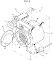
- FIG. 1 is a perspective view illustrating a washing machine according to an embodiment of the present disclosure.
- the washing machine 1 includes a main body 10 defining an outer appearance of the washing machine 1, a wash tub 20 placed in the main body 10, and a rotating tub 30 rotatably placed in the wash tub 20.
- a drive device (not shown) is installed in the main body 10 to rotate the rotating tub 30 forward or in reverse.
- the wash tub 20 is provided at a front side thereof with an opening 21, through which laundry is put into the rotating tub 30.
- a door 40 is installed to a front surface of the main body 10 to open or close the opening 21.
- the door 40 is provided with a transparent door glass 41 to allow a user to observe the interior of the rotating tub 30 with the naked eye.
- a detergent feeding device 50 is installed above the wash tub 20 to feed detergent-dissolved wash water into the wash tub 20.
- the detergent feeding device 50 includes a forwardly or rearwardly movable detergent container 51 in which the detergent is accommodated.
- a drain pump 60 and a drain pipe 61 are installed below the wash tub 20 to discharge the wash water from the interior of the wash tub 20 to the outside of the main body 10.
- a front plate 11 is provided at an upper end of the front surface of the main body 10 to define a corner where the front surface and an upper surface of the main body 10 meet.
- the front plate 11 may be prefabricated and then, be mounted to the main body 10, or may be integrally formed with the main body 10.
- the washing machine 1 performs washing, rinsing, and dehydrating operations.
- the washing operation may be subdivided in consideration of the kind and contamination degree of laundry, etc., to allow the user to select a suitable washing operation for the laundry.
- the washing machine 1 may function to display operational modes thereof to the user.
- the washing machine 1 includes a control panel 100 to enable manipulation of the washing machine 1 by the user and display operational modes of the washing machine 1.
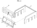
- FIG. 2 is a view illustrating the control panel separated from the washing machine according to the embodiment of the present disclosure.
- the control panel 100 is coupled to the front plate 11 from the upper side.
- the front plate 11 is provided with coupling holes 12, into which coupling hooks 114 of the control panel 100 are inserted. As such, a lower end of the control panel 100 is hooked to the front plate 11.
- various other fitting methods using recesses and bosses, etc. may be used.
- the front plate 11 is further provided with a cable hole 14, through which, e.g., a power cable to supply power to the control panel 100 and a control cable to control a drive device installed behind the rotating tub 30 to rotate the rotating tub 30 may pass.
- the front plate 11 has a control panel mounting recess 13 indented in a front surface thereof, in which a control unit assembly (120, see FIG. 3 ) which will be described hereinafter is seated.
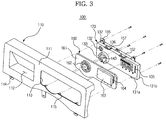
- FIG. 3 is an exploded perspective view of the control panel according to the embodiment
- FIGS. 4 and 5 are exploded perspective views illustrating the control unit assembly constituting the control panel according to the embodiment.
- the control panel 100 includes a control panel frame 110, a display panel 160 coupled to the control panel frame 110, and the control unit assembly 120 placed behind the display panel 160.
- the control panel frame 110 includes a main frame portion 111 provided with fastening bosses 115 protruding rearward from an inner surface thereof.
- the fastening bosses 115 are screwed to the control unit assembly 120.
- the control panel frame 110 is attached to a front upper position of the washing machine 1 illustrated in FIG. 1 .
- the main frame portion 111 of the control panel frame 110 is perforated with a detergent container entrance/exit opening 112, through which the detergent container 51 is movable forward or rearward, and a display panel coupling opening 113 for coupling of the display panel 160.
- the display panel coupling opening 113 may have a shape corresponding to that of the display panel 160.
- the coupling hooks 114 protrude downward from a lower surface of the control panel frame 110.
- the display panel 160 has a plate shape.
- the display panel 160 includes a rotating knob mount 162, on which a rotating knob (not shown) is mounted, a display part 163 to display operational modes of the washing machine 1, and a button mount 164 on which buttons (not shown) to enable manipulation of the washing machine 1 by the user are mounted, all of which are arranged on a front surface 161 of the display panel 160.
- the rotating knob mount 162 is centrally perforated with a hole through which a rotating shaft of a rotary switch 143 which will be described hereinafter penetrates.
- the rotating knob mount 162 is provided with a guide groove to guide rotation of the rotating knob (not shown).
- the display part 163 is printed with, e.g., letters or figures to indicate operational modes of the washing machine 1. As light emitted from the control unit assembly 120 behind the display part 163 penetrates the display part 163, operational modes of the washing machine 1 are displayed. To this end, the display part 163 is made of a light transparent material. The display part 163 may be made of transparent or semi-transparent plastic.
- the button mount 164 may be provided with the plurality of buttons (not shown).
- a button rubber (not shown) having a shape corresponding to that of the button mount 164 may be provided behind the display panel 160.
- the button rubber (not shown) transmits user button input pressure to the control unit assembly 120 and allows the buttons (not shown) to be returned to original positions thereof when the user button input pressure is released.
- the display panel 160 may be coupled to the control panel frame 110 using hooks, screws, etc.
- the display panel 160 need not be directly coupled to the control frame 110, but may instead come into close contact with the periphery of the display panel coupling opening 113 of the control panel frame 110 because the control unit assembly 120 supports a rear surface of the display panel 160.
- the rotating knob mount 162 and the button mount 164 need not be provided at the display panel 160, but may instead be provided at the main frame portion 111 of the control panel frame 110.
- the display panel 160 may be integrally formed with the control panel frame 110 so as to constitute a part of the control panel frame 110.
- control unit assembly 120 includes a circuit board 140, a circuit board housing 130 to which the circuit board 140 is coupled, and a main control unit 150 placed behind the circuit board 140.
- only one circuit board may be provided, or a plurality of circuit boards may be provided. If the plurality of circuit boards 140 is provided, the circuit boards 140 may be connected to one another via a cable (not shown).
- the circuit board 140 is provided at a front surface 141 a thereof with a speaker 142 to output sound depending on operational modes, the rotary switch 143 coupled to the rotating knob (not shown), light emitting elements 144 for display of operational modes, and switches 145 to which the user button input pressure is applied. That is, the front surface 141 a of the circuit board 140 provides an element mounting surface.
- the light emitting elements 144 may be turned on or off or may emit different colors of light based on operational modes.
- the light emitting elements 144 may include Light Emitting Diodes (LEDs).
- the circuit board housing 130 includes a front wall portion 131 a and a sidewall portion 131 b angled rearward from an edge of the front surface portion 131 a.
- the circuit board 140 is accommodated in the circuit board housing 130 such that the front surface 141 a thereof, on which the elements are mounted, faces an inner wall surface of the front wall portion 131 a of the circuit board housing 130.
- the front wall portion 131 a of the circuit board housing 130 is provided with a sound passage 132 through which sound of the speaker 142 passes, a light guide 134 to guide light emitted from the light emitting elements 144 forward, and button input holes 135 to transmit the user button input pressure to the switches 145.
- the sound passage 132, light guide 134 and button input holes 135 are respectively arranged close to the speaker 142, light emitting elements 144 and switches 145 when the circuit board 140 is coupled to the circuit board housing 130.
- the sidewall portion 131b of the circuit board housing 130 is provided with at least one fastening flange 137 having a fastening hole and at least one coupling piece 136 for coupling of the main control unit 150.
- a plurality of fastening flanges 137 and a plurality of coupling pieces 136 may be provided.
- the circuit board housing 130 has an open rear side.
- a rearwardly open space defined by the front wall portion 131 a and the sidewall portion 131b of the circuit board housing 130 defines a circuit board mounting space 138.
- the circuit board 140 is accommodated in the circuit board mounting space 138 such that the front surface 141 a thereof, on which the elements are mounted, faces the inner wall surface of the front wall portion 131 a of the circuit board housing 130.
- the circuit board 140 may be inserted into the circuit board mounting space 138 of the circuit board housing 130 through the open rear side of the circuit board housing 130.
- the circuit board 140 accommodated in the circuit board mounting region 130 may be coupled to the circuit board housing 130 using fastening members, such as screws (not shown), hooks (not shown) provided at the inner wall surface of the front wall portion 131 a of the circuit board housing 130, etc.
- the circuit board housing 130 is made of a fire-retardant material.
- the circuit board housing 130 may be made of fire-retardant plastic.
- the front surface 141 a of the circuit board 140, on which the elements are mounted, may be burned by overheating or electric defects. Covering the front surface 141 a of the circuit board 140 with the fire-retardant circuit board housing 130 may prevent transfer of heat from the circuit board housing 130 even if fire occurs on the front surface 141 a of the circuit board 140.
- the front wall portion 131 a of the circuit board housing 130 is provided at a rear surface thereof with support protrusions 139.
- the support protrusions 139 support the front surface 141 a of the circuit board 140 such that the circuit board 140 is spaced apart from the front wall portion 131 a of the circuit board housing 130 by a predetermined distance. Even in the case where the circuit board 140 is spaced apart from the front wall portion 131 a of the circuit board housing 130, to prevent scatting of light emitted from the light emitting elements 144, the light emitting elements 144 of the circuit board 140 may come into close contact with the light guide 134 of the circuit board housing 130.
- the main control unit 150 includes a front wall portion 151 and a sidewall portion 152 angled rearward from an edge of the front wall portion 151.
- the main control unit 150 has an open rear side and provides an element mounting space 154 defined by the front wall portion 151 and the sidewall portion 152.
- a circuit board (not shown) is accommodated in the element mounting space 154 and a variety of elements 155 is mounted on the circuit board (not shown).
- the elements 155 include control elements to control various operations of the washing machine 1 and power supply elements to supply power to the variety of elements.
- the circuit board 140 is connected to the main control unit 150 via a connecting member, such as a cable, etc.
- the sidewall portion 131b of the main control unit 150 is provided with at least one coupling hook 157 and at least one fastening flange 156.
- the coupling hook 157 of the main control unit 150 is coupled to the coupling piece 136 of the circuit board housing 130
- the main control unit 150 is coupled to the circuit board housing 130.
- the main control unit 150 covers at least a part of the open rear side of the circuit board housing 130.
- the front surface 141 a and a rear surface 141 b of the circuit board 140 may be respectively supported by the inner wall surface of the front wall portion 131 a of the circuit board housing 130 and the front wall portion 151 of the main control unit 150.
- the fastening flange 156 of the main control unit 150 comes into contact with the fastening flange 137 of the circuit board housing 130.
- the control unit assembly 120 is secured to the control panel frame 110.
- the front wall portion 151 of the main control unit 150 may be provided with support protrusions 153.
- the support protrusions 153 support the rear surface 141 b of the circuit board 140.
- the circuit board 140 may be kept in a fixed position within the circuit board housing 130 as the support protrusions 139 of the circuit board housing 130 support the front surface 141 a of the circuit board 140 and the support protrusions 153 of the main control unit 150 support the rear surface 141 b of the circuit board 140.
- the main control unit 150 is made of a fire-retardant material, similar to the circuit board housing 130. Thus, as the main control unit 150 covers the rear surface 141 b of the circuit board 140, it may be possible to prevent transfer of heat from the main control unit 150 even if fire occurs on the circuit board 140.
- the main control unit 150 has conventionally been located distantly from the control panel 100.
- the control panel 100 including the circuit board housing 130 according to the embodiment may have a reduced thickness in a front-and-rear direction and thus, the main control unit 150 may be located close to the control panel 100.
- one or more embodiments include a washing machine in which a circuit board housing placed in front of a circuit board functions to guide light emitted from light emitting elements forward and support buttons, thereby preventing deterioration in display quality due to scattering of light and deterioration in button operation performance.
- the multifunctional circuit board housing may further enable reduction in the number of constituent elements of the control panel, resulting in a simplified assembly process and reduced production costs.
- circuit board housing and a main control unit which are made of fire-retardant materials, at front and rear surfaces of the circuit board, it may be possible to prevent transfer of heat even if fire occurs on the circuit board even without coating an element mounting surface of the circuit board with an insulating material such as urethane, etc.
- control panel is thinner, which allows the main control unit, which has conventionally been mounted separately in the washing machine, to be integrally formed with the control panel, resulting in enhanced space utilization within the washing machine.
Landscapes
- Engineering & Computer Science (AREA)
- Textile Engineering (AREA)
- Microelectronics & Electronic Packaging (AREA)
- Detail Structures Of Washing Machines And Dryers (AREA)
Claims (11)
- Machine à laver (1) comprenant :un corps principal (10) ; etun panneau de contrôle (100),dans laquelle le panneau de contrôle (100) comprend un châssis de panneau de contrôle (110) assemblé sur la portion supérieure du corps principal (10), un boîtier de circuit imprimé (130) couplé à un côté arrière du châssis de panneau de contrôle (110) et comportant un côté arrière ouvert, et un circuit imprimé (140) logé dans le boîtier de circuit imprimé (130), etdans laquelle le circuit imprimé (140) est inséré dans le boîtier de circuit imprimé (130) à travers le côté arrière ouvert du boîtier de circuit imprimé de telle sorte qu'une surface avant correspondante, sur laquelle sont montés des éléments luminescents (144) pour afficher des modes de fonctionnement de la machine à laver, fait face à une surface de paroi interne d'une portion de paroi avant du boîtier de circuit imprimé,caractérisée en ce queledit panneau de contrôle comprend en outre :un panneau d'affichage (160) placé entre le châssis de panneau de contrôle (110) et le boîtier de circuit imprimé (130) de manière à transmettre la lumière émise par les éléments luminescents (144), et une unité de contrôle principale (150) couplée à un côté arrière du boîtier de circuit imprimé (130) et placée sur un côté arrière du circuit imprimé (140) de manière à alimenter le circuit imprimé (140) et à contrôler le fonctionnement des éléments luminescents (144), dans laquelle le boîtier de circuit imprimé (130) est couplé au châssis de panneau de contrôle et pourvu sur une surface avant correspondante avec un guide de lumière (134) pour guider la lumière vers l'avant.
- Machine à laver selon la revendication 1, dans laquelle le boîtier de circuit imprimé (130) comprend la portion de paroi avant (131a) pourvue d'un guide de lumière (134) pour guider la lumière émise par les éléments luminescents (144) vers l'avant, une portion de paroi latérale (131b) inclinée vers l'arrière depuis un bord de la portion de paroi avant (131a), et un espace de montage de circuit imprimé (138) défini par la portion de paroi avant et la portion de paroi latérale.
- Machine à laver selon la revendication 2, dans laquelle la surface de paroi interne de la portion de paroi avant (131a) du boîtier de circuit imprimé (130) supporte la surface avant du circuit imprimé (140).
- Machine à laver selon la revendication 2, dans laquelle le boîtier de circuit imprimé (130) comprend en outre un support de bouton (133) pourvu sur la portion de paroi avant correspondante pour supporter un bouton grâce auquel une pression d'entrée de bouton d'utilisateur est appliquée.
- Machine à laver selon la revendication 1, dans laquelle le boîtier de circuit imprimé est réalisé en plastique ignifugé.
- Machine à laver selon la revendication 1, dans laquelle l'unité de contrôle principale (150) est couplée au boîtier de circuit imprimé (130) pour blinder au moins une partie du côté arrière ouvert du boîtier de circuit imprimé.
- Machine à laver selon la revendication 6,
dans laquelle l'unité de contrôle principale (150) comprend une pluralité d'éléments (155) et un boîtier d'unité de contrôle comprenant un espace de montage d'éléments (154) dans lequel les éléments sont montés, et
dans laquelle le boîtier d'unité de contrôle comprend une portion de paroi avant adjacente à une surface arrière du circuit imprimé. - Machine à laver selon la revendication 7, dans laquelle la portion de paroi avant (151) du boîtier d'unité de contrôle supporte la surface arrière (141b) du circuit imprimé (140) pour fixer le circuit imprimé au boîtier de circuit imprimé quand l'unité de contrôle principale est couplée au boîtier de circuit imprimé (130).
- Machine à laver selon la revendication 1, dans laquelle la surface avant (141a) du circuit imprimé (140) ne comporte aucun revêtement ignifugé.
- Machine à laver selon la revendication 1, dans laquelle le boîtier de circuit imprimé (130) comprend une protubérance de support (139) qui ressort vers l'arrière pour supporter la surface avant (141a) du circuit imprimé (140).
- Machine à laver selon la revendication 1, dans laquelle l'unité de contrôle principale est couplée au côté arrière du boîtier de circuit imprimé (130) pour recouvrir au moins une partie du côté arrière ouvert du boîtier de circuit imprimé, l'unité de contrôle principale supportant une surface arrière du circuit imprimé quand elle est couplée au boîtier de circuit imprimé.
Applications Claiming Priority (1)
| Application Number | Priority Date | Filing Date | Title |
|---|---|---|---|
| KR1020100137645A KR20120075794A (ko) | 2010-12-29 | 2010-12-29 | 세탁기 |
Publications (2)
| Publication Number | Publication Date |
|---|---|
| EP2471990A1 EP2471990A1 (fr) | 2012-07-04 |
| EP2471990B1 true EP2471990B1 (fr) | 2016-07-27 |
Family
ID=45464362
Family Applications (1)
| Application Number | Title | Priority Date | Filing Date |
|---|---|---|---|
| EP11195729.6A Active EP2471990B1 (fr) | 2010-12-29 | 2011-12-27 | Machine à laver |
Country Status (4)
| Country | Link |
|---|---|
| US (1) | US9080272B2 (fr) |
| EP (1) | EP2471990B1 (fr) |
| KR (1) | KR20120075794A (fr) |
| CN (1) | CN102535107B (fr) |
Families Citing this family (17)
| Publication number | Priority date | Publication date | Assignee | Title |
|---|---|---|---|---|
| CN105051283B (zh) * | 2012-11-14 | 2017-03-29 | 阿塞里克股份有限公司 | 包括触摸按钮的家用电器 |
| USD759916S1 (en) * | 2014-10-21 | 2016-06-21 | Samsung Electronics Co., Ltd. | Control panel for washing machine |
| USD759917S1 (en) * | 2014-10-21 | 2016-06-21 | Samsung Electronics Co., Ltd. | Control panel for washing machine |
| CN105782806B (zh) * | 2014-12-26 | 2019-11-19 | 博西华电器(江苏)有限公司 | 家用电器 |
| US9732963B2 (en) * | 2015-06-17 | 2017-08-15 | Haier Us Appliance Solutions, Inc. | Appliance control panel assembly |
| CN107366132B (zh) * | 2016-05-13 | 2024-08-20 | 合肥海尔洗衣机有限公司 | 一种易拆卸控制盘结构及其装配方法 |
| CN108221281B (zh) * | 2016-12-15 | 2021-06-04 | 合肥海尔洗衣机有限公司 | Rgb三色灯显示模组及设有该显示模组的洗衣机 |
| JP6445093B2 (ja) * | 2017-06-02 | 2018-12-26 | 東芝ライフスタイル株式会社 | ドラム式洗濯機 |
| CN108660692B (zh) * | 2018-05-16 | 2023-11-21 | 佛山海尔滚筒洗衣机有限公司 | 一种洗衣机控制面板组件及洗衣机 |
| CN111434833B (zh) * | 2019-01-10 | 2022-11-15 | 博西华电器(江苏)有限公司 | 控制面板、其制造方法及具有其的洗衣机 |
| CN110438749A (zh) * | 2019-08-20 | 2019-11-12 | 无锡小天鹅电器有限公司 | 一种操作面板及具有其的衣物处理装置 |
| KR102386710B1 (ko) | 2020-08-10 | 2022-04-14 | 엘지전자 주식회사 | 의류처리장치 |
| EP4202102A4 (fr) | 2021-03-04 | 2024-03-13 | Samsung Electronics Co., Ltd. | Machine à laver et appareil d'entretien des vêtements |
| CN115110259B (zh) * | 2021-03-19 | 2025-12-23 | 青岛海尔滚筒洗衣机有限公司 | 一种衣物处理设备的电路板安装结构及衣物处理设备 |
| EP4520861B1 (fr) * | 2022-05-31 | 2026-04-01 | Wuxi Little Swan Electric Co., Ltd. | Structure de montage d'affichage et équipement de traitement de vêtements |
| KR20250084631A (ko) * | 2023-12-04 | 2025-06-11 | 엘지전자 주식회사 | 의류처리장치 |
| CN120625320A (zh) * | 2024-03-12 | 2025-09-12 | Lg电子株式会社 | 衣物处理装置 |
Family Cites Families (20)
| Publication number | Priority date | Publication date | Assignee | Title |
|---|---|---|---|---|
| US5464955A (en) * | 1993-04-15 | 1995-11-07 | Emerson Electric Co. | Backlit appliance control console |
| JP2004522309A (ja) * | 2001-06-22 | 2004-07-22 | エルジー エレクトロニクス インコーポレイティド | 家電機器用コントロールパネル組立体及びその製造方法 |
| KR100971015B1 (ko) * | 2002-11-28 | 2010-07-20 | 엘지전자 주식회사 | 세탁기의 컨트롤 장치 |
| US7038156B2 (en) * | 2003-08-27 | 2006-05-02 | Lg Electronics Inc. | Rotary knob assembly for home appliance |
| PL1523022T3 (pl) * | 2003-09-17 | 2012-04-30 | Pas Deutschland Gmbh | Układ przycisków do panelu obsługi |
| CN1645994A (zh) * | 2004-01-20 | 2005-07-27 | 迪尔阿扣基金两合公司 | 塑料外壳 |
| KR20050086199A (ko) * | 2004-02-25 | 2005-08-30 | 엘지전자 주식회사 | 세탁기의 컨트롤 장치 |
| KR101100155B1 (ko) * | 2004-06-01 | 2011-12-28 | 엘지전자 주식회사 | 컨트롤 패널 어셈블리의 버튼 조립체 |
| KR20060031064A (ko) | 2004-10-07 | 2006-04-12 | 엘지전자 주식회사 | 세탁기의 컨트롤장치 |
| KR101203549B1 (ko) | 2005-05-23 | 2012-11-21 | 엘지전자 주식회사 | 세탁기의 컨트롤 패널 |
| KR101233156B1 (ko) * | 2005-10-13 | 2013-02-15 | 엘지전자 주식회사 | 세탁기 |
| JP2008006046A (ja) | 2006-06-29 | 2008-01-17 | Matsushita Electric Ind Co Ltd | 洗濯機 |
| WO2008026844A2 (fr) * | 2006-08-31 | 2008-03-06 | Lg Electronics Inc. | Ensemble panneau de commande pour appareil de blanchisserie, et appareil de blanchisserie pourvu de ce panneau |
| KR101285377B1 (ko) * | 2006-09-07 | 2013-07-10 | 엘지전자 주식회사 | 세탁장치용 컨트롤 패널 어셈블리 |
| CN101177887B (zh) | 2006-11-08 | 2010-08-25 | 南京乐金熊猫电器有限公司 | 洗衣机的控制面板 |
| KR101356648B1 (ko) | 2007-03-12 | 2014-02-03 | 삼성전자주식회사 | 컨트롤패널 및 이를 갖춘 세탁기 |
| KR101309298B1 (ko) * | 2007-05-25 | 2013-09-17 | 삼성전자주식회사 | 세탁기 및 그 컨트롤 패널 어셈블리 |
| CN201129642Y (zh) * | 2007-11-29 | 2008-10-08 | 博西华电器(江苏)有限公司 | 发光二极管显示模组以及使用该模组的洗涤设备 |
| KR20100083508A (ko) * | 2009-01-14 | 2010-07-22 | 삼성전자주식회사 | 컨트롤패널 어셈블리 및 이를 구비한 세탁기 |
| KR20100094676A (ko) | 2009-02-19 | 2010-08-27 | 엘지전자 주식회사 | 컨트롤패널 조립부 및 이를 구비하는 세탁장치 |
-
2010
- 2010-12-29 KR KR1020100137645A patent/KR20120075794A/ko not_active Ceased
-
2011
- 2011-12-27 EP EP11195729.6A patent/EP2471990B1/fr active Active
- 2011-12-27 US US13/337,953 patent/US9080272B2/en active Active
- 2011-12-29 CN CN201110460437.XA patent/CN102535107B/zh active Active
Also Published As
| Publication number | Publication date |
|---|---|
| US20120169193A1 (en) | 2012-07-05 |
| CN102535107A (zh) | 2012-07-04 |
| KR20120075794A (ko) | 2012-07-09 |
| CN102535107B (zh) | 2016-03-23 |
| EP2471990A1 (fr) | 2012-07-04 |
| US9080272B2 (en) | 2015-07-14 |
Similar Documents
| Publication | Publication Date | Title |
|---|---|---|
| EP2471990B1 (fr) | Machine à laver | |
| EP2650422B1 (fr) | Ensemble de panneau de commande et machine à laver l'utilisant | |
| KR101880083B1 (ko) | 세탁기 | |
| EP2031112B1 (fr) | Appareil de manipulation de vêtements disposant d'un bouton pour l'ensemble du panneau de commande | |
| AU2022205217B2 (en) | Panel assembly for a home appliance and home appliance therewith | |
| RU2324778C2 (ru) | Устройство панели управления для бытовой машины | |
| US12235035B2 (en) | Refrigerator and home appliance | |
| EP2394556A2 (fr) | Lave-vaisselle intégré | |
| EP4462046A1 (fr) | Appareil électroménager | |
| KR102629009B1 (ko) | 세탁기 | |
| KR101963249B1 (ko) | 세탁기 | |
| KR20070066604A (ko) | 세탁기의 엘이디 서포터 방수 구조 | |
| KR20190034175A (ko) | 세탁기 | |
| KR20170082707A (ko) | 컨트롤 패널 장치 및 이를 구비한 세탁기 | |
| KR20230011148A (ko) | 냉장고 및 가전기기 | |
| KR20050091408A (ko) | 세탁기의 버튼 조립구조 | |
| KR20070081676A (ko) | 컨트롤부 케이블 손상 방지 구조를 갖는 세탁 또는 건조기 |
Legal Events
| Date | Code | Title | Description |
|---|---|---|---|
| AK | Designated contracting states |
Kind code of ref document: A1 Designated state(s): AL AT BE BG CH CY CZ DE DK EE ES FI FR GB GR HR HU IE IS IT LI LT LU LV MC MK MT NL NO PL PT RO RS SE SI SK SM TR |
|
| AX | Request for extension of the european patent |
Extension state: BA ME |
|
| PUAI | Public reference made under article 153(3) epc to a published international application that has entered the european phase |
Free format text: ORIGINAL CODE: 0009012 |
|
| RAP1 | Party data changed (applicant data changed or rights of an application transferred) |
Owner name: SAMSUNG ELECTRONICS CO., LTD. |
|
| 17P | Request for examination filed |
Effective date: 20130103 |
|
| 17Q | First examination report despatched |
Effective date: 20140205 |
|
| GRAP | Despatch of communication of intention to grant a patent |
Free format text: ORIGINAL CODE: EPIDOSNIGR1 |
|
| INTG | Intention to grant announced |
Effective date: 20160210 |
|
| GRAS | Grant fee paid |
Free format text: ORIGINAL CODE: EPIDOSNIGR3 |
|
| GRAA | (expected) grant |
Free format text: ORIGINAL CODE: 0009210 |
|
| AK | Designated contracting states |
Kind code of ref document: B1 Designated state(s): AL AT BE BG CH CY CZ DE DK EE ES FI FR GB GR HR HU IE IS IT LI LT LU LV MC MK MT NL NO PL PT RO RS SE SI SK SM TR |
|
| REG | Reference to a national code |
Ref country code: GB Ref legal event code: FG4D |
|
| REG | Reference to a national code |
Ref country code: CH Ref legal event code: EP |
|
| REG | Reference to a national code |
Ref country code: AT Ref legal event code: REF Ref document number: 815890 Country of ref document: AT Kind code of ref document: T Effective date: 20160815 |
|
| REG | Reference to a national code |
Ref country code: IE Ref legal event code: FG4D |
|
| REG | Reference to a national code |
Ref country code: DE Ref legal event code: R096 Ref document number: 602011028530 Country of ref document: DE |
|
| REG | Reference to a national code |
Ref country code: LT Ref legal event code: MG4D |
|
| REG | Reference to a national code |
Ref country code: NL Ref legal event code: MP Effective date: 20160727 |
|
| REG | Reference to a national code |
Ref country code: AT Ref legal event code: MK05 Ref document number: 815890 Country of ref document: AT Kind code of ref document: T Effective date: 20160727 |
|
| PG25 | Lapsed in a contracting state [announced via postgrant information from national office to epo] |
Ref country code: IT Free format text: LAPSE BECAUSE OF FAILURE TO SUBMIT A TRANSLATION OF THE DESCRIPTION OR TO PAY THE FEE WITHIN THE PRESCRIBED TIME-LIMIT Effective date: 20160727 Ref country code: NL Free format text: LAPSE BECAUSE OF FAILURE TO SUBMIT A TRANSLATION OF THE DESCRIPTION OR TO PAY THE FEE WITHIN THE PRESCRIBED TIME-LIMIT Effective date: 20160727 Ref country code: NO Free format text: LAPSE BECAUSE OF FAILURE TO SUBMIT A TRANSLATION OF THE DESCRIPTION OR TO PAY THE FEE WITHIN THE PRESCRIBED TIME-LIMIT Effective date: 20161027 Ref country code: RS Free format text: LAPSE BECAUSE OF FAILURE TO SUBMIT A TRANSLATION OF THE DESCRIPTION OR TO PAY THE FEE WITHIN THE PRESCRIBED TIME-LIMIT Effective date: 20160727 Ref country code: IS Free format text: LAPSE BECAUSE OF FAILURE TO SUBMIT A TRANSLATION OF THE DESCRIPTION OR TO PAY THE FEE WITHIN THE PRESCRIBED TIME-LIMIT Effective date: 20161127 Ref country code: FI Free format text: LAPSE BECAUSE OF FAILURE TO SUBMIT A TRANSLATION OF THE DESCRIPTION OR TO PAY THE FEE WITHIN THE PRESCRIBED TIME-LIMIT Effective date: 20160727 Ref country code: LT Free format text: LAPSE BECAUSE OF FAILURE TO SUBMIT A TRANSLATION OF THE DESCRIPTION OR TO PAY THE FEE WITHIN THE PRESCRIBED TIME-LIMIT Effective date: 20160727 Ref country code: HR Free format text: LAPSE BECAUSE OF FAILURE TO SUBMIT A TRANSLATION OF THE DESCRIPTION OR TO PAY THE FEE WITHIN THE PRESCRIBED TIME-LIMIT Effective date: 20160727 |
|
| PG25 | Lapsed in a contracting state [announced via postgrant information from national office to epo] |
Ref country code: BE Free format text: LAPSE BECAUSE OF FAILURE TO SUBMIT A TRANSLATION OF THE DESCRIPTION OR TO PAY THE FEE WITHIN THE PRESCRIBED TIME-LIMIT Effective date: 20160727 Ref country code: PL Free format text: LAPSE BECAUSE OF FAILURE TO SUBMIT A TRANSLATION OF THE DESCRIPTION OR TO PAY THE FEE WITHIN THE PRESCRIBED TIME-LIMIT Effective date: 20160727 Ref country code: PT Free format text: LAPSE BECAUSE OF FAILURE TO SUBMIT A TRANSLATION OF THE DESCRIPTION OR TO PAY THE FEE WITHIN THE PRESCRIBED TIME-LIMIT Effective date: 20161128 Ref country code: GR Free format text: LAPSE BECAUSE OF FAILURE TO SUBMIT A TRANSLATION OF THE DESCRIPTION OR TO PAY THE FEE WITHIN THE PRESCRIBED TIME-LIMIT Effective date: 20161028 Ref country code: ES Free format text: LAPSE BECAUSE OF FAILURE TO SUBMIT A TRANSLATION OF THE DESCRIPTION OR TO PAY THE FEE WITHIN THE PRESCRIBED TIME-LIMIT Effective date: 20160727 Ref country code: SE Free format text: LAPSE BECAUSE OF FAILURE TO SUBMIT A TRANSLATION OF THE DESCRIPTION OR TO PAY THE FEE WITHIN THE PRESCRIBED TIME-LIMIT Effective date: 20160727 Ref country code: AT Free format text: LAPSE BECAUSE OF FAILURE TO SUBMIT A TRANSLATION OF THE DESCRIPTION OR TO PAY THE FEE WITHIN THE PRESCRIBED TIME-LIMIT Effective date: 20160727 Ref country code: LV Free format text: LAPSE BECAUSE OF FAILURE TO SUBMIT A TRANSLATION OF THE DESCRIPTION OR TO PAY THE FEE WITHIN THE PRESCRIBED TIME-LIMIT Effective date: 20160727 |
|
| PG25 | Lapsed in a contracting state [announced via postgrant information from national office to epo] |
Ref country code: RO Free format text: LAPSE BECAUSE OF FAILURE TO SUBMIT A TRANSLATION OF THE DESCRIPTION OR TO PAY THE FEE WITHIN THE PRESCRIBED TIME-LIMIT Effective date: 20160727 Ref country code: EE Free format text: LAPSE BECAUSE OF FAILURE TO SUBMIT A TRANSLATION OF THE DESCRIPTION OR TO PAY THE FEE WITHIN THE PRESCRIBED TIME-LIMIT Effective date: 20160727 |
|
| REG | Reference to a national code |
Ref country code: DE Ref legal event code: R097 Ref document number: 602011028530 Country of ref document: DE |
|
| PG25 | Lapsed in a contracting state [announced via postgrant information from national office to epo] |
Ref country code: SK Free format text: LAPSE BECAUSE OF FAILURE TO SUBMIT A TRANSLATION OF THE DESCRIPTION OR TO PAY THE FEE WITHIN THE PRESCRIBED TIME-LIMIT Effective date: 20160727 Ref country code: BG Free format text: LAPSE BECAUSE OF FAILURE TO SUBMIT A TRANSLATION OF THE DESCRIPTION OR TO PAY THE FEE WITHIN THE PRESCRIBED TIME-LIMIT Effective date: 20161027 Ref country code: CZ Free format text: LAPSE BECAUSE OF FAILURE TO SUBMIT A TRANSLATION OF THE DESCRIPTION OR TO PAY THE FEE WITHIN THE PRESCRIBED TIME-LIMIT Effective date: 20160727 Ref country code: SM Free format text: LAPSE BECAUSE OF FAILURE TO SUBMIT A TRANSLATION OF THE DESCRIPTION OR TO PAY THE FEE WITHIN THE PRESCRIBED TIME-LIMIT Effective date: 20160727 Ref country code: DK Free format text: LAPSE BECAUSE OF FAILURE TO SUBMIT A TRANSLATION OF THE DESCRIPTION OR TO PAY THE FEE WITHIN THE PRESCRIBED TIME-LIMIT Effective date: 20160727 |
|
| PLBE | No opposition filed within time limit |
Free format text: ORIGINAL CODE: 0009261 |
|
| STAA | Information on the status of an ep patent application or granted ep patent |
Free format text: STATUS: NO OPPOSITION FILED WITHIN TIME LIMIT |
|
| 26N | No opposition filed |
Effective date: 20170502 |
|
| REG | Reference to a national code |
Ref country code: CH Ref legal event code: PL |
|
| PG25 | Lapsed in a contracting state [announced via postgrant information from national office to epo] |
Ref country code: SI Free format text: LAPSE BECAUSE OF FAILURE TO SUBMIT A TRANSLATION OF THE DESCRIPTION OR TO PAY THE FEE WITHIN THE PRESCRIBED TIME-LIMIT Effective date: 20160727 |
|
| PG25 | Lapsed in a contracting state [announced via postgrant information from national office to epo] |
Ref country code: MC Free format text: LAPSE BECAUSE OF FAILURE TO SUBMIT A TRANSLATION OF THE DESCRIPTION OR TO PAY THE FEE WITHIN THE PRESCRIBED TIME-LIMIT Effective date: 20160727 |
|
| REG | Reference to a national code |
Ref country code: FR Ref legal event code: ST Effective date: 20170831 |
|
| REG | Reference to a national code |
Ref country code: IE Ref legal event code: MM4A |
|
| PG25 | Lapsed in a contracting state [announced via postgrant information from national office to epo] |
Ref country code: LU Free format text: LAPSE BECAUSE OF NON-PAYMENT OF DUE FEES Effective date: 20161227 Ref country code: FR Free format text: LAPSE BECAUSE OF NON-PAYMENT OF DUE FEES Effective date: 20170102 Ref country code: CH Free format text: LAPSE BECAUSE OF NON-PAYMENT OF DUE FEES Effective date: 20161231 Ref country code: LI Free format text: LAPSE BECAUSE OF NON-PAYMENT OF DUE FEES Effective date: 20161231 |
|
| PG25 | Lapsed in a contracting state [announced via postgrant information from national office to epo] |
Ref country code: IE Free format text: LAPSE BECAUSE OF NON-PAYMENT OF DUE FEES Effective date: 20161227 |
|
| PG25 | Lapsed in a contracting state [announced via postgrant information from national office to epo] |
Ref country code: HU Free format text: LAPSE BECAUSE OF FAILURE TO SUBMIT A TRANSLATION OF THE DESCRIPTION OR TO PAY THE FEE WITHIN THE PRESCRIBED TIME-LIMIT; INVALID AB INITIO Effective date: 20111227 Ref country code: CY Free format text: LAPSE BECAUSE OF FAILURE TO SUBMIT A TRANSLATION OF THE DESCRIPTION OR TO PAY THE FEE WITHIN THE PRESCRIBED TIME-LIMIT Effective date: 20160727 |
|
| PG25 | Lapsed in a contracting state [announced via postgrant information from national office to epo] |
Ref country code: TR Free format text: LAPSE BECAUSE OF FAILURE TO SUBMIT A TRANSLATION OF THE DESCRIPTION OR TO PAY THE FEE WITHIN THE PRESCRIBED TIME-LIMIT Effective date: 20160727 Ref country code: MK Free format text: LAPSE BECAUSE OF FAILURE TO SUBMIT A TRANSLATION OF THE DESCRIPTION OR TO PAY THE FEE WITHIN THE PRESCRIBED TIME-LIMIT Effective date: 20160727 |
|
| PG25 | Lapsed in a contracting state [announced via postgrant information from national office to epo] |
Ref country code: MT Free format text: LAPSE BECAUSE OF NON-PAYMENT OF DUE FEES Effective date: 20161227 |
|
| PG25 | Lapsed in a contracting state [announced via postgrant information from national office to epo] |
Ref country code: AL Free format text: LAPSE BECAUSE OF FAILURE TO SUBMIT A TRANSLATION OF THE DESCRIPTION OR TO PAY THE FEE WITHIN THE PRESCRIBED TIME-LIMIT Effective date: 20160727 |
|
| PGFP | Annual fee paid to national office [announced via postgrant information from national office to epo] |
Ref country code: GB Payment date: 20211122 Year of fee payment: 11 |
|
| GBPC | Gb: european patent ceased through non-payment of renewal fee |
Effective date: 20221227 |
|
| PG25 | Lapsed in a contracting state [announced via postgrant information from national office to epo] |
Ref country code: GB Free format text: LAPSE BECAUSE OF NON-PAYMENT OF DUE FEES Effective date: 20221227 |
|
| PGFP | Annual fee paid to national office [announced via postgrant information from national office to epo] |
Ref country code: DE Payment date: 20251120 Year of fee payment: 15 |