EP2472038B1 - Charnière de porte de véhicule automobile - Google Patents
Charnière de porte de véhicule automobile Download PDFInfo
- Publication number
- EP2472038B1 EP2472038B1 EP11170714.7A EP11170714A EP2472038B1 EP 2472038 B1 EP2472038 B1 EP 2472038B1 EP 11170714 A EP11170714 A EP 11170714A EP 2472038 B1 EP2472038 B1 EP 2472038B1
- Authority
- EP
- European Patent Office
- Prior art keywords
- vehicle door
- motor vehicle
- unit
- bracket
- hinge pin
- Prior art date
- Legal status (The legal status is an assumption and is not a legal conclusion. Google has not performed a legal analysis and makes no representation as to the accuracy of the status listed.)
- Not-in-force
Links
- 230000008859 change Effects 0.000 claims description 13
- 230000000903 blocking effect Effects 0.000 description 19
- 238000001514 detection method Methods 0.000 description 9
- 230000001419 dependent effect Effects 0.000 description 5
- 230000004913 activation Effects 0.000 description 4
- 238000010586 diagram Methods 0.000 description 4
- 238000006073 displacement reaction Methods 0.000 description 4
- 238000011161 development Methods 0.000 description 3
- 230000018109 developmental process Effects 0.000 description 3
- 230000009467 reduction Effects 0.000 description 2
- 230000006978 adaptation Effects 0.000 description 1
- 238000010276 construction Methods 0.000 description 1
- 230000008878 coupling Effects 0.000 description 1
- 238000010168 coupling process Methods 0.000 description 1
- 238000005859 coupling reaction Methods 0.000 description 1
- 230000003247 decreasing effect Effects 0.000 description 1
- 230000000694 effects Effects 0.000 description 1
- 230000005764 inhibitory process Effects 0.000 description 1
- 238000003780 insertion Methods 0.000 description 1
- 230000037431 insertion Effects 0.000 description 1
- 230000003993 interaction Effects 0.000 description 1
- 230000002028 premature Effects 0.000 description 1
- 230000000284 resting effect Effects 0.000 description 1
Images

Classifications
-
- E—FIXED CONSTRUCTIONS
- E05—LOCKS; KEYS; WINDOW OR DOOR FITTINGS; SAFES
- E05D—HINGES OR SUSPENSION DEVICES FOR DOORS, WINDOWS OR WINGS
- E05D11/00—Additional features or accessories of hinges
- E05D11/08—Friction devices between relatively-movable hinge parts
- E05D11/082—Friction devices between relatively-movable hinge parts with substantially radial friction, e.g. cylindrical friction surfaces
- E05D11/084—Friction devices between relatively-movable hinge parts with substantially radial friction, e.g. cylindrical friction surfaces the friction depending on direction of rotation or opening angle of the hinge
-
- E—FIXED CONSTRUCTIONS
- E05—LOCKS; KEYS; WINDOW OR DOOR FITTINGS; SAFES
- E05D—HINGES OR SUSPENSION DEVICES FOR DOORS, WINDOWS OR WINGS
- E05D11/00—Additional features or accessories of hinges
- E05D11/10—Devices for preventing movement between relatively-movable hinge parts
- E05D11/1028—Devices for preventing movement between relatively-movable hinge parts for maintaining the hinge in two or more positions, e.g. intermediate or fully open
- E05D11/105—Devices for preventing movement between relatively-movable hinge parts for maintaining the hinge in two or more positions, e.g. intermediate or fully open the maintaining means acting perpendicularly to the pivot axis
- E05D11/1057—Devices for preventing movement between relatively-movable hinge parts for maintaining the hinge in two or more positions, e.g. intermediate or fully open the maintaining means acting perpendicularly to the pivot axis specially adapted for vehicles
-
- E—FIXED CONSTRUCTIONS
- E05—LOCKS; KEYS; WINDOW OR DOOR FITTINGS; SAFES
- E05F—DEVICES FOR MOVING WINGS INTO OPEN OR CLOSED POSITION; CHECKS FOR WINGS; WING FITTINGS NOT OTHERWISE PROVIDED FOR, CONCERNED WITH THE FUNCTIONING OF THE WING
- E05F5/00—Braking devices, e.g. checks; Stops; Buffers
-
- E—FIXED CONSTRUCTIONS
- E05—LOCKS; KEYS; WINDOW OR DOOR FITTINGS; SAFES
- E05Y—INDEXING SCHEME ASSOCIATED WITH SUBCLASSES E05D AND E05F, RELATING TO CONSTRUCTION ELEMENTS, ELECTRIC CONTROL, POWER SUPPLY, POWER SIGNAL OR TRANSMISSION, USER INTERFACES, MOUNTING OR COUPLING, DETAILS, ACCESSORIES, AUXILIARY OPERATIONS NOT OTHERWISE PROVIDED FOR, APPLICATION THEREOF
- E05Y2201/00—Constructional elements; Accessories therefor
- E05Y2201/20—Brakes; Disengaging means; Holders; Stops; Valves; Accessories therefor
- E05Y2201/21—Brakes
-
- E—FIXED CONSTRUCTIONS
- E05—LOCKS; KEYS; WINDOW OR DOOR FITTINGS; SAFES
- E05Y—INDEXING SCHEME ASSOCIATED WITH SUBCLASSES E05D AND E05F, RELATING TO CONSTRUCTION ELEMENTS, ELECTRIC CONTROL, POWER SUPPLY, POWER SIGNAL OR TRANSMISSION, USER INTERFACES, MOUNTING OR COUPLING, DETAILS, ACCESSORIES, AUXILIARY OPERATIONS NOT OTHERWISE PROVIDED FOR, APPLICATION THEREOF
- E05Y2201/00—Constructional elements; Accessories therefor
- E05Y2201/20—Brakes; Disengaging means; Holders; Stops; Valves; Accessories therefor
- E05Y2201/23—Actuation thereof
- E05Y2201/246—Actuation thereof by auxiliary motors, magnets, springs or weights
-
- E—FIXED CONSTRUCTIONS
- E05—LOCKS; KEYS; WINDOW OR DOOR FITTINGS; SAFES
- E05Y—INDEXING SCHEME ASSOCIATED WITH SUBCLASSES E05D AND E05F, RELATING TO CONSTRUCTION ELEMENTS, ELECTRIC CONTROL, POWER SUPPLY, POWER SIGNAL OR TRANSMISSION, USER INTERFACES, MOUNTING OR COUPLING, DETAILS, ACCESSORIES, AUXILIARY OPERATIONS NOT OTHERWISE PROVIDED FOR, APPLICATION THEREOF
- E05Y2201/00—Constructional elements; Accessories therefor
- E05Y2201/20—Brakes; Disengaging means; Holders; Stops; Valves; Accessories therefor
- E05Y2201/25—Mechanical means for force or torque adjustment therefor
-
- E—FIXED CONSTRUCTIONS
- E05—LOCKS; KEYS; WINDOW OR DOOR FITTINGS; SAFES
- E05Y—INDEXING SCHEME ASSOCIATED WITH SUBCLASSES E05D AND E05F, RELATING TO CONSTRUCTION ELEMENTS, ELECTRIC CONTROL, POWER SUPPLY, POWER SIGNAL OR TRANSMISSION, USER INTERFACES, MOUNTING OR COUPLING, DETAILS, ACCESSORIES, AUXILIARY OPERATIONS NOT OTHERWISE PROVIDED FOR, APPLICATION THEREOF
- E05Y2201/00—Constructional elements; Accessories therefor
- E05Y2201/20—Brakes; Disengaging means; Holders; Stops; Valves; Accessories therefor
- E05Y2201/252—Type of friction
- E05Y2201/26—Mechanical friction
-
- E—FIXED CONSTRUCTIONS
- E05—LOCKS; KEYS; WINDOW OR DOOR FITTINGS; SAFES
- E05Y—INDEXING SCHEME ASSOCIATED WITH SUBCLASSES E05D AND E05F, RELATING TO CONSTRUCTION ELEMENTS, ELECTRIC CONTROL, POWER SUPPLY, POWER SIGNAL OR TRANSMISSION, USER INTERFACES, MOUNTING OR COUPLING, DETAILS, ACCESSORIES, AUXILIARY OPERATIONS NOT OTHERWISE PROVIDED FOR, APPLICATION THEREOF
- E05Y2201/00—Constructional elements; Accessories therefor
- E05Y2201/20—Brakes; Disengaging means; Holders; Stops; Valves; Accessories therefor
- E05Y2201/262—Type of motion, e.g. braking
- E05Y2201/266—Type of motion, e.g. braking rotary
-
- E—FIXED CONSTRUCTIONS
- E05—LOCKS; KEYS; WINDOW OR DOOR FITTINGS; SAFES
- E05Y—INDEXING SCHEME ASSOCIATED WITH SUBCLASSES E05D AND E05F, RELATING TO CONSTRUCTION ELEMENTS, ELECTRIC CONTROL, POWER SUPPLY, POWER SIGNAL OR TRANSMISSION, USER INTERFACES, MOUNTING OR COUPLING, DETAILS, ACCESSORIES, AUXILIARY OPERATIONS NOT OTHERWISE PROVIDED FOR, APPLICATION THEREOF
- E05Y2201/00—Constructional elements; Accessories therefor
- E05Y2201/40—Motors; Magnets; Springs; Weights; Accessories therefor
- E05Y2201/46—Magnets
- E05Y2201/462—Electromagnets
-
- E—FIXED CONSTRUCTIONS
- E05—LOCKS; KEYS; WINDOW OR DOOR FITTINGS; SAFES
- E05Y—INDEXING SCHEME ASSOCIATED WITH SUBCLASSES E05D AND E05F, RELATING TO CONSTRUCTION ELEMENTS, ELECTRIC CONTROL, POWER SUPPLY, POWER SIGNAL OR TRANSMISSION, USER INTERFACES, MOUNTING OR COUPLING, DETAILS, ACCESSORIES, AUXILIARY OPERATIONS NOT OTHERWISE PROVIDED FOR, APPLICATION THEREOF
- E05Y2400/00—Electronic control; Electrical power; Power supply; Power or signal transmission; User interfaces
- E05Y2400/10—Electronic control
- E05Y2400/32—Position control, detection or monitoring
- E05Y2400/334—Position control, detection or monitoring by using pulse generators
- E05Y2400/336—Position control, detection or monitoring by using pulse generators of the angular type
-
- E—FIXED CONSTRUCTIONS
- E05—LOCKS; KEYS; WINDOW OR DOOR FITTINGS; SAFES
- E05Y—INDEXING SCHEME ASSOCIATED WITH SUBCLASSES E05D AND E05F, RELATING TO CONSTRUCTION ELEMENTS, ELECTRIC CONTROL, POWER SUPPLY, POWER SIGNAL OR TRANSMISSION, USER INTERFACES, MOUNTING OR COUPLING, DETAILS, ACCESSORIES, AUXILIARY OPERATIONS NOT OTHERWISE PROVIDED FOR, APPLICATION THEREOF
- E05Y2900/00—Application of doors, windows, wings or fittings thereof
- E05Y2900/50—Application of doors, windows, wings or fittings thereof for vehicles
- E05Y2900/53—Type of wing
- E05Y2900/531—Doors
Definitions
- the invention relates to a motor vehicle door hinge with a locking unit for locking a vehicle door with respect to a vehicle body, with a door console can be arranged on the door and a door console can be arranged on the vehicle body, via a hinge pin articulated on one of the door and column console and on the other is arranged rotationally fixed door and column console, the locking unit is fixed to the one of door bracket and column console and relative to the hinge pin between a blocking position and a release position adjustable locking element and an adjusting unit for adjusting the locking element between the blocking position and the Has release position.
- Motor vehicle door hinges of the type mentioned are known in various configurations from the prior art. They allow the connection of a vehicle door to a vehicle body, wherein the integrated locking units serve to secure the vehicle door in predetermined angular positions, so that can be dispensed with separate lock.
- the locking units of generic motor vehicle door hinges generally have fixed locking angles in which the motor vehicle door is secured against undesired further pivoting.
- a generic motor vehicle door hinge is further from the DE 10 2010 011627 A1 known.
- the holding contour thus permanently defines the opening angle-dependent clamping force of the motor vehicle door hinge. An opening angle independent, dependent on the operating state of the motor vehicle door hinge variable determination of the clamping force is not possible.
- the invention has for its object to provide a motor vehicle door hinge with a locking unit, which allows reliable locking of a vehicle door connected to the motor vehicle door hinge under changing conditions.
- the motor vehicle door hinge has a door bracket, which is connectable to the vehicle door, and connectable to the vehicle body pillar console, the door console and the pillar bracket - to ensure a pivoting of an associated with the motor vehicle door hinge motor vehicle door - are hingedly connected to each other via a hinge pin.
- the hinge pin is connected either rotationally fixed to the column console or the door bracket and hinged to the other console.
- the locking unit of the motor vehicle door hinge has a locking element, which is fixed to the bracket, which is pivotally connected to the hinge pin.
- a determination of the locking of the motor vehicle door hinge in positions between a maximum opening position of the motor vehicle door and its closed position, wherein the positions are determined by the pivot angle range of the door bracket relative to the column console, is effected by an actuation of the locking element which is adjustable relative to the hinge pin between a blocking position and a release position. In the blocking position, the locking element prevents or inhibits unwanted pivoting of the door due to its interaction with the hinge pin.
- the locking element acts directly with the hinge pin and inhibits at least the pivoting, so that an increased operating torque is required.
- the locking element In the release position, however, the locking element is in a position relative to the hinge pin, in which a pivoting of the motor vehicle door can be done with a low operating torque.
- an adjustment can be provided in which the locking element between the door bracket completely defining and a completely out of engagement with the hinge pin position can be moved in the the locking element exerts no influence on the actuating torque.
- an actuating unit To adjust the locking element between the blocking position and the release position is an actuating unit, wherein the adjusting unit according to the invention in turn connected to this driving and detecting the operating state of the vehicle door control unit.
- the actuator thus serves to adjust the locking element in the desired - dependent on the operating state of the vehicle door - position.
- Essential operating conditions are, on the one hand, the determination of a pivoting movement of the vehicle door and the existing pivoting angle of the door console opposite the pillar console, which results in the opening angle of the door.
- the setting unit serves to position the locking element in such a way that a pivoting movement of the motor vehicle door can largely take place with a low actuating torque.
- the adjusting unit serves to adjust the locking element in the direction of the blocking position, so as to prevent unintentional adjustment of the motor vehicle door to prevent from the set position.
- the adjusting unit is actuated via the control unit, which is also designed to detect the operating states of the motor vehicle door.
- control unit makes it possible to set the holding force generated by the locking unit regardless of the opening angle of the raftGermane.
- identical opening angles can be assigned as many, depending solely on the operating state of the vehicle door holding forces.
- the motor vehicle door hinge according to the invention is distinguished by its particularly high operating comfort, the use of an actuating unit connected to the locking element, which is controlled by a control unit which detects the operating states, ensuring reliable operation.
- the motor vehicle door hinge according to the invention can be adapted via the control unit to different manufacturer-specific specifications, wherein this can be done via a different type of control of the adjustment.
- customer-specific states of the locking unit can be assigned in a simple manner to the various operating states of a vehicle door connected to the motor vehicle door hinge.
- the drive of the actuator is carried out according to the invention via the control unit, the specific embodiment is basically freely selectable.
- the control unit can have a pneumatic and / or hydraulic drive unit.
- the control unit has a drive unit, in particular an electromechanical drive unit, which is connected to the setting unit such that an actuation of the drive unit is an adjustment of an actuating element engaged with the locking element of the setting unit between a position associated with the release position and a blocking position causes.
- the actuating element thus determines, depending on its position, the holding force caused by the locking element.
- the drive unit serves to drive the actuating unit and thus to effect an adjustment of the actuating element, so that this is adjusted at least between the positions which are associated with the release position and the blocking position of the locking element.
- a drive unit to a control unit allows a particularly compact design, in particular, an electromechanical drive unit provides a cost effective and reliable way to drive the actuator.
- the drive unit has a drive motor, in particular an electric motor, which is in engagement with the actuating element.
- a drive motor in particular an electric motor
- the use of an electric motor is particularly suitable for connection to the control element, after this only a coupling of the output shaft of the drive motor is required with the actuator.
- the adjusting element can be displaced particularly accurately and quickly by the drive motor, so that a particularly rapid adaptation of the motor vehicle door hinge to the respective operating states is possible.
- control unit In addition to the drive of the control unit, the control unit also serves to detect the operating state of the vehicle door. As already mentioned, the corresponding configuration of the control unit and the type of operating states to be detected are basically freely selectable. According to a particularly advantageous embodiment of the invention, however, the control unit has means for detecting the pivoting angle and / or a pivoting movement of the door bracket relative to the column console. The detection of the pivoting movement of the door panel directly opposite the column console, which is directly associated with the pivoting movement of a vehicle door, makes it possible to determine whether the door has been moved or has already completed a pivotal movement and the door has been arranged in the desired holding position.
- the detection of the pivot angle also makes it possible to accurately detect the door position, so that there is the possibility to provide pivoting angle-dependent positions of the locking element.
- the control unit formed in this way allows the detection of an intended pivoting of the door by means of a movement detection, the determination of the adjustment of the control unit to be carried out being basically freely selectable.
- the detection of the swivel angle can be done in any way.
- the means for detecting the pivoting angle is formed by a signal sensor, which is located in operative connection with a arranged on the hinge pin signal generator.
- the pivot angle can be determined directly in the area of the arrester, so that a particularly compact design is possible.
- the swivel angle detection takes place directly on the mutually pivoted parts, a very accurate detection of the actual swivel angle is possible.
- control unit controls the drive unit as a function of the pivoting angle and / or a pivoting movement of the door console relative to the column console, wherein at a standstill of the door console opposite the column console, the drive unit, the actuator in the direction of the blocking position associated position and displaced in a pivoting of the door bracket relative to the column console in the direction of the release position associated position.
- the control unit can interact directly with the drive unit and control it in accordance with a predetermined program.
- the activation of the drive unit selected by the control unit can be defined by suitable control programs in which the individual operating states are assigned to states of the drive unit that correspond to the customer's wishes.
- the control unit controls the drive unit in such a way that the actuating element is in a swivel angle range around the closed position of the vehicle door, in particular in the swivel angle range of up to 25 °, particularly preferably up to 15 °, starting from the closed position. is adjusted in the direction of the release position associated position.
- This embodiment of the invention makes it possible to close or open the door in any case in a particularly simple and comfortable manner, after in the area around the closed position of the door by the locking preferably no inhibition of movement by the locking element.
- this embodiment of the invention allows the detection of a pivoting movement, so that there is no premature blocking of the pivoting movement by activation of the actuating unit.
- a closing The door can be performed in a simple manner without increased effort, after the door in the area around the closed position is unloaded by the locking element pivotable.
- the control unit controls the drive unit such that the actuator in the swivel angle range to the maximum opening position of the door, in particular in the swivel angle range of up to 10 °, preferably up to 5 ° before the maximum opening position, in Direction shifted to the blocking position assigned position.
- the actuating torque is increased in the specified angular range by the activation of the actuating element and a displacement of the locking element in the direction of the blocking position. The door is thereby protected against displacement of the door at increased speed in the end stop.
- the locking unit acts as an end stop damper, wherein the control unit can be designed such that it increasingly adjusted with decreasing distance of the door from the end stop the actuating element in the direction of the blocking position.
- the locking element is formed by a coaxial with the hinge pin arranged Umschlingungsklammer with a longitudinal axis of the hinge pin extending slot, wherein the opening width of the slot for adjusting the looping between the release position and the blocking position is adjustable by the actuator.
- the wrap clamp engages the hinge pin in a predetermined portion of the hinge pin.
- the friction to be achieved can be defined in a particularly simple and cost-effective manner via the wrap angle, which also results in the opening width of the slot, so that the motor vehicle door hinge designed according to the above development can be produced particularly cost-effectively.
- a simple determination of the actuating element can also be achieved via the choice of material and the surface quality and the resulting friction pairing between the hinge pin and the looping clip.
- the embodiment of the looping clip is basically freely selectable, as already explained above, wherein the surface provided for friction with the hinge pin can be adjusted via the looping angle and along its length.
- the wrap-around bracket has one on the Hinge pin arranged clamping portion and two such adjoining areas of the slot on the clamping portion subsequent clamping leg, that a change in the distance of the facing inner sides of the clamping legs causes a change in the opening width.
- An actuating unit can thus be used, which only requires a smaller amount of force to actuate the locking element than is the case with an immediate connection in the region of the hinge pin.
- the operating torque defining diameter of the clamping portion of the looping clamp is determined by the change in the distance of the clamping legs to each other, with increasing distance from the clamping portion even small changes in the distance of the clamping legs to each other have a significant change in the operating torque result.
- the locking element is fixedly arranged on the console, which is adjustable relative to the hinge pin.
- the hinge pin is rotationally connected to the column console, the locking element is rotationally arranged on the door bracket, so that a pivoting movement of the door bracket directly an adjustment of the locking member relative to the hinge pin has the consequence over the friction with the Hinge pin determines the required to pivot the door actuating torque.
- the corresponding arrangement of the locking element which is designed as a wrap-around, is basically arbitrary. According to a particularly advantageous embodiment of the invention, however, in the embodiment of the locking element as a loop clamp, the first clamping leg with its outer side with the setting unit and the second clamping leg with its outer side with an inner wall a housing of the arrester unit is engaged.
- the looping clip is supported by the outer sides of the two clamping legs on the inner wall of the housing or on the setting unit, which in turn is connected to the bracket pivotally connected to the hinge pin, preferably the door bracket.
- a rotation of the wrap is excluded by this embodiment of the invention, after the second clamping leg is fixed in its position by the inner wall and the first clamping leg on the setting unit.
- the adjusting unit makes it possible to adjust the first clamping leg relative to the second clamping leg, whereby, depending on the thereby adjusting opening width of the looping clamp, the moment required for actuation is determined.
- a further and complicated and cost-increasing attachment of the looping clip is not required according to this embodiment of the invention, which can also be mounted in a simple manner beyond.
- the locking element takes place in the embodiment of the locking element as wrap loop with two clamping legs, of which the first rests with its outer side with the actuator and the second with its outer side on an inner wall of a housing, a determination of the actuating torque on the setting unit, through the the distance between the first and second clamping legs is determined.
- the individual positions of the actuator unit unique positions of the clamping legs are assigned to each other.
- the outside of the second clamping leg rests against a screwed into the housing and protruding from the inner wall of the housing adjusting screw.
- the outer side of the second clamping leg is not directly adjacent to a housing inner wall, but is supported on a projecting into the housing from adjusting screw. The distance of the outer side of the second clamping leg from the inner wall of the housing can thus be determined via the screw-in depth of the adjusting screw, so that identical positions of the actuating unit are assigned different opening widths of the slot between the clamping legs can.
- this embodiment of the invention allows the determination of different operating torque curves with otherwise identical construction of the motor vehicle door hinge.
- the use of a screw provides the ability to subsequently correct the moment of actuation torque, to adapt to changing requirements or to meet special customer requirements.
- the adjusting screw is preferably accessible from an outer side of the housing, so that a comfortable adjustability is given.
- the configuration of the setting unit such that it cooperates with the locking element, preferably the first clamping leg in the direction of the second clamping leg can be adjusted in distance, is also basically freely selectable. According to a particularly advantageous embodiment of the invention, however, the outer side of the first clamping leg bears against a variable contact surface of the adjusting element of the adjusting unit that is variable with respect to the second clamping leg.
- this embodiment of the invention is in the area between the release position and the blocking position a permanent contact surface of a contact surface of the actuating element on the outside of the first clamping leg.
- the distance between the voltage applied to the outside of the first clamping leg contact surface relative to the second clamping leg is modifiable via actuation of the adjusting unit, which inevitably results in a change in the distance between the two clamping legs to each other, preferably achieved by the adjusting element displacement of the clamping legs to each other in elastic region of the looping takes place, so that without further aids a permanent contact surface is ensured on the outside of the first clamping leg.
- the outside of the first clamping leg particularly preferably has a web resting against the contact surface, as a result of which a particularly reliable adjustment of the first clamping leg relative to the second clamping leg can be realized.
- the web can be formed integrally with the first clamping leg, but also be formed by a connected to the first clamping leg component, wherein the web also may be formed by deviating from the material of the belt clip materials, which are adapted to the friction load.
- the adjusting element is formed by a camshaft arranged on an eccentric cam, which is designed such that a rotation of the preferably parallel to the hinge pin extending camshaft causes a change in the distance of the contact surface of the eccentric cam to the second clamping leg.
- the eccentric cam which extends particularly advantageously in the axial direction of the hinge pin as far as possible over the length of the first clamping leg, has a contact surface whose distance from the camshaft changes in the circumferential direction to achieve an adjustment of the first clamping leg in dependence of the rotation of the camshaft.
- the distance between the first and second clamping legs can be determined by a simple rotation of the camshaft carrying the eccentric cam.
- the configuration of the eccentric cam determines depending on the angle of rotation of the camshaft, the specified operating torque, wherein the contour of the contact surface of the eccentric cam further defines the course of the actuating torque between the blocking position and the release position.
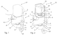
- FIG. 1 to 5 shown motor vehicle door hinge 33 has a door bracket 2 and a pillar bracket 1, which are hingedly connected to each other via a hinge pin 3.
- the hinge pin 3 is arranged against rotation with a mounting portion 24 in a receiving opening of a boom 5 of the column bracket 1, wherein the mounting portion 24 may be polygonal to prevent rotation of the hinge pin 3, for example., And the receiving opening in the boom 5 is formed accordingly.
- the door bracket 2 is hinged relative to the hinge pin 3.
- the articulated connection takes place via a pivotal mounting of the hinge pin 3 to a housing base bushing 14 and a housing cover sleeve 18 of a rotationally fixed to the door bracket 2 connected housing 6 a locking unit 4.
- the housing base bushing 14 and the housing cover sleeve 18 are formed on the housing bottom 11 and housing cover 10 which serve to close the housing 6 in the axial direction of the hinge pin 3.
- the door bracket 2 can be pivoted relative to the hinge pin 3, wherein the locking unit 4 is mitverschwenkt relative to the hinge pin 3.
- the pivotal movement of the door bracket 2 relative to the column console 1 in the opening direction is limited by an end stop, which is formed by an attached to the housing 6 boom 8 and arranged on the pillar bracket 1 stop 7, which abut each other in the maximum opening position.
- a sliding washer 13 is arranged between the housing base bushing 14 and a the insertion depth of the hinge pin 3 in the receiving opening on the boom 5 limiting flange 12.
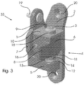
- the clamping portion 21 coaxial with the hinge pin 3, wherein the clamping portion 21, the hinge pin 3, however, does not completely surround. Therefore, the clamping portion 21 has a slot extending in the axial direction of the hinge pin 3, the opening width of which can be varied by the distance between two clamping legs 22, 23 adjoining the clamping portion 21 in the region of the slot.
- the second clamping leg 23 is supported with its outer side relative to the housing 6.
- the support takes place on a screwed into the housing 6 screw 16, which protrudes from the inside of the housing 6, so that the outside of the second clamping leg 23 rests against the adjusting screw 16.
- a change in the slot width by a change in the distance between the clamping legs 22, 23 take place in that the first clamping leg 22 is adjusted relative to the second clamping leg 23.
- an actuating unit 29 which has an eccentric cam 15 designed as an actuating element 15 which is arranged on a rotatably mounted relative to the housing 6 camshaft 9.
- the bearing of the camshaft 9 takes place via bearing bushes 34, which are arranged in suitable openings in the housing bottom 11 and in the housing cover 10.
- the eccentric cam 15 rests with a contact surface 36 against a web 35 arranged on the outside of the first clamping leg 22.
- a camshaft 25 is arranged, which is in operative connection with an output shaft 31 of an electric motor 28.
- the electric motor 28 is part of a control unit 27, which also has a signal sensor 30.
- the control unit 27 has a control unit housing 32, which is fixed to the housing 6 of the locking unit 4.
- the signal sensor 30 is thereby in operative connection with a signal transmitter 26 arranged on the end of the hinge pin 3 and makes it possible to detect the swivel angle of the door bracket 2 relative to the column console 1 and to determine a successful pivoting movement.
- the control unit 27 controls the electric motor 28, which causes an adjustment of the actuating element 15 of the actuating unit 29 via the output shaft 31.
- the door console 2 and the column console 1 have suitable openings 20 for receiving fastening means, for example rivets 19.
Landscapes
- Engineering & Computer Science (AREA)
- Mechanical Engineering (AREA)
- Lock And Its Accessories (AREA)
Claims (12)
- Charnière de porte de véhicule automobile avec une unité de blocage (4) pour l'arrêt d'une porte de véhicule par rapport à une carrosserie de véhicule, avec une console de porte (2) pouvant être agencée sur la porte de véhicule et une console de colonne (1) pouvant être agencée sur la carrosserie de véhicule qui sont reliées entre elles par articulation par une tige de charnière (3) qui est agencée par articulation sur l'une de la console de porte (2) et console de colonne (1) et sans pouvoir tourner sur l'autre de la console de porte (2) et console de colonne (1), l'unité de blocage (4) présentant un élément d'arrêt fixé sur l'une de la console de porte (2) et console de colonne (1) et réglable par rapport à la tige de charnière (3) entre une position de blocage et une position de libération, ainsi qu'une unité de réglage (29) pour le réglage de l'élément d'arrêt entre la position de blocage et la position de libération, l'élément d'arrêt étant formé par une attache d'enroulement (17) agencée coaxialement à la tige de charnière (3) avec une fente s'étendant dans le sens axial longitudinal de la tige de charnière (3), dont la largeur d'ouverture est réglable pour le réglage de l'attache d'enroulement (17) entre la position de libération et la position de blocage par l'unité de réglage (29) et l'attache d'enroulement (17) présentant une section de serrage (21) agencée sur la tige de charnière (3) ainsi que deux branches de serrage (22, 23) raccordées sur des zones en regard de la fente à la section de serrage (21), de telle manière qu'une modification de la distance entre les côtés intérieurs tournés l'un vers l'autre de la première et seconde branches (22, 23) provoque une modification de la largeur d'ouverture,
caractérisée en ce que
l'unité de réglage (29) est reliée à une unité de commande (27) entraînant celle-ci ainsi que détectant l'état de fonctionnement de la porte de véhicule, l'unité de commande (27) présentant une unité d'entraînement (28) qui est reliée à l'unité de réglage (29) de telle manière qu'un actionnement de l'unité d'entraînement (28) provoque un réglage d'un élément de réglage (15), se trouvant en engagement avec l'élément d'arrêt (17), de l'unité de réglage (29) entre une position associée à la position de libération et une position associée à la position de blocage, l'unité d'entraînement présentant un moteur d'entraînement (28) se trouvant en engagement avec l'élément de réglage (15) et l'élément de réglage étant formé par une came excentrique (15) agencée sur un arbre à came (9) qui est réalisée de telle manière qu'une rotation de l'arbre à came (9) provoque une modification de la distance entre la surface de contact (36) de la came excentrique (15) et la seconde branche de serrage (23). - Charnière de porte de véhicule automobile selon la revendication 1, caractérisée en ce que le moteur d'entraînement (28) est un moteur électrique.
- Charnière de porte de véhicule automobile selon l'une ou plusieurs quelconques des revendications précédentes, caractérisée en ce que l'unité de commande (27) présente un moyen (30) pour la détection de l'angle de pivotement et/ou d'un mouvement pivotant de la console de porte (2) par rapport à la console de colonne (1).
- Charnière de porte de véhicule automobile selon l'une ou plusieurs quelconques des revendications précédentes, caractérisée en ce que le moyen est formé pour la détection de l'angle de pivotement par un récepteur de signal (30) qui se trouve en liaison active avec un émetteur de signal (26) agencé sur la tige de charnière (3).
- Charnière de porte de véhicule automobile selon l'une ou plusieurs quelconques des revendications précédentes, caractérisée en ce que l'unité de commande (27) commande l'unité d'entraînement (28) en fonction de l'angle de pivotement et/ou d'un mouvement de pivotement de la console de porte (2) par rapport à la console de colonne (1), lors d'un arrêt de la console de porte (2) par rapport à la console de colonne (1), l'unité d'entraînement (28) déplaçant l'élément de réglage (15) en direction de la position associée à la position de blocage et lors d'un pivotement de la console de porte (2) par rapport à la console de colonne (1) en direction de la position associée à la position de libération.
- Charnière de porte de véhicule automobile selon l'une ou plusieurs quelconques des revendications précédentes, caractérisée en ce que l'unité de commande (27) commande l'unité d'entraînement (28) de telle manière que l'élément de réglage (15) se trouve dans une plage d'angle de pivotement autour de la position de fermeture de la charnière de porte de véhicule automobile (33), en particulier dans la plage d'angle de pivotement jusqu'à 25°, de manière particulièrement préférée jusqu'à 15°, à partir de la position de fermeture, dans la position associée à la position de libération.
- Charnière de porte de véhicule automobile selon l'une quelconque des revendications précédentes, caractérisée en ce que l'unité de commande (27) commande l'unité d'entraînement (28) de telle manière. que l'élément de réglage (15) soit déplacé dans la plage d'angle de pivotement autour de la position d'ouverture maximale de la charnière de porte de véhicule automobile (33), en particulier dans la plage d'angle de pivotement jusqu'à 10°, de préférence jusqu'à 5° avant la position d'ouverture maximale en direction de la position associée à la position de blocage.
- Charnière de porte de véhicule automobile selon l'une ou plusieurs quelconques des revendications précédentes, caractérisée en ce que la première branche de serrage (22) se trouve en engagement avec son côté extérieur avec l'unité de réglage (29) et la seconde branche de serrage se trouve en engagement avec son côté extérieur avec une paroi intérieure d'un boîtier (6) de l'élément de blocage.
- Charnière de porte de véhicule automobile selon l'une ou plusieurs quelconques des revendications précédentes, caractérisée en ce que le côté extérieur de la seconde branche de serrage (23) repose contre une vis de serrage (16) pouvant être vissée dans le boîtier (6) et dépassant de la paroi intérieure du boîtier (6).
- Charnière de porte de véhicule automobile selon l'une ou plusieurs quelconques des revendications précédentes, caractérisée en ce que le côté extérieur de la première branche de serrage (22) repose contre une surface de contact (36), dont la distance en distance par rapport à la seconde branche de serrage (23) de l'élément de réglage (15) de l'unité de réglage (29) est modifiable.
- Charnière de porte de véhicule automobile selon l'une ou plusieurs quelconques des revendications précédentes, caractérisée en ce que la surface de contact (26) repose contre une nervure (35) agencée sur le côté extérieur de la première branche de serrage (22).
- Charnière de porte de véhicule automobile selon l'une ou plusieurs quelconques des revendications précédentes, caractérisée en ce que l'arbre à came (9) s'étend parallèlement à la tige de charnière (3).
Priority Applications (1)
| Application Number | Priority Date | Filing Date | Title |
|---|---|---|---|
| EP11170714.7A EP2472038B1 (fr) | 2011-06-21 | 2011-06-21 | Charnière de porte de véhicule automobile |
Applications Claiming Priority (1)
| Application Number | Priority Date | Filing Date | Title |
|---|---|---|---|
| EP11170714.7A EP2472038B1 (fr) | 2011-06-21 | 2011-06-21 | Charnière de porte de véhicule automobile |
Publications (2)
| Publication Number | Publication Date |
|---|---|
| EP2472038A1 EP2472038A1 (fr) | 2012-07-04 |
| EP2472038B1 true EP2472038B1 (fr) | 2016-05-04 |
Family
ID=44907712
Family Applications (1)
| Application Number | Title | Priority Date | Filing Date |
|---|---|---|---|
| EP11170714.7A Not-in-force EP2472038B1 (fr) | 2011-06-21 | 2011-06-21 | Charnière de porte de véhicule automobile |
Country Status (1)
| Country | Link |
|---|---|
| EP (1) | EP2472038B1 (fr) |
Families Citing this family (2)
| Publication number | Priority date | Publication date | Assignee | Title |
|---|---|---|---|---|
| DE102012024375A1 (de) * | 2012-12-13 | 2014-06-18 | Kiekert Aktiengesellschaft | Vorrichtung und Verfahren zur Betätigung einer Kraftfahrzeug-Schließeinrichtung |
| CN106761098B (zh) * | 2016-12-30 | 2018-05-04 | 龙岩学院 | 车门防夹伤系统及其控制方法 |
Citations (1)
| Publication number | Priority date | Publication date | Assignee | Title |
|---|---|---|---|---|
| DE102010011627A1 (de) * | 2010-03-16 | 2010-10-14 | Daimler Ag | Scharnier für ein Schwenkelement eines Kraftwagens |
Family Cites Families (6)
| Publication number | Priority date | Publication date | Assignee | Title |
|---|---|---|---|---|
| DE1901123A1 (de) * | 1969-01-10 | 1970-07-16 | Eltreva Ag | Bremse fuer Drehfenster |
| DE19537816A1 (de) * | 1995-10-11 | 1997-04-17 | Scharwaechter Gmbh Co Kg | Stufenloser hilfskraftbetätigter Kraftwagentürfeststeller |
| DE20206861U1 (de) * | 2002-04-30 | 2003-09-04 | Friedr. Fingscheidt GmbH, 42551 Velbert | Stufenloser Türfeststeller |
| DE102005050706A1 (de) * | 2005-10-22 | 2007-05-03 | Daimlerchrysler Ag | Feststellbremse für eine Fahrzeugtür |
| US20080309120A1 (en) * | 2007-06-15 | 2008-12-18 | Kohlstrand Kelly M | Automotive door with repositionable immobilizer |
| DE102007027867A1 (de) * | 2007-06-18 | 2008-12-24 | Continental Automotive Gmbh | Verfahren und Anordnung zur Ansteuerung zumindest einer elektromechanischen Bremsaktuatoreinheit einer Türbremseinrichtung |
-
2011
- 2011-06-21 EP EP11170714.7A patent/EP2472038B1/fr not_active Not-in-force
Patent Citations (1)
| Publication number | Priority date | Publication date | Assignee | Title |
|---|---|---|---|---|
| DE102010011627A1 (de) * | 2010-03-16 | 2010-10-14 | Daimler Ag | Scharnier für ein Schwenkelement eines Kraftwagens |
Also Published As
| Publication number | Publication date |
|---|---|
| EP2472038A1 (fr) | 2012-07-04 |
Similar Documents
| Publication | Publication Date | Title |
|---|---|---|
| EP2809861B1 (fr) | Mécanisme de commande pour un abattant d'un meuble | |
| EP3198097B1 (fr) | Charnière pour meubles | |
| EP3475508B1 (fr) | Ferrure de meuble | |
| EP1934423B1 (fr) | Ferrure pour abattant | |
| DE10253138B4 (de) | Türvorrichtung für ein Fahrzeug und Verfahren zum Steuern einer Bewegung einer Tür | |
| EP2142045A2 (fr) | Meuble et dispositif pour éjecter un élément de meuble | |
| DE102015216536B3 (de) | Klemmvorrichtung einer verstellbaren Lenksäule für Kraftfahrzeuge | |
| EP3708753B1 (fr) | Ferrure de couvercle destinée à la fixation pivotante d'un couvercle de meuble sur un corps de meuble | |
| EP3310639B1 (fr) | Colonne de direction muni d'un dispositif de fixation électromécanique | |
| EP2167766B1 (fr) | Dispositif d'actionnement d'une serrure d'une pièce mobile | |
| EP3045636A1 (fr) | Mécanisme d'aide à l'ouverture et à la fermeture avec dispositif de régulation pour fenêtre ou porte | |
| EP2037027B1 (fr) | Guide-fil pour machine à tricoter rectiligne | |
| EP2472038B1 (fr) | Charnière de porte de véhicule automobile | |
| DE102015000452A1 (de) | Vorrichtung zur Unterstützung und Erleichterung des Öffnens und Schließens für ein Fenster oder eine Tür | |
| DE102008056430B3 (de) | Haubenscharnier für Kraftfahrzeuge | |
| EP3623559B1 (fr) | Ferrure de couvercle destinée à la fixation pivotante d'un couvercle de meuble à un corps de meuble | |
| DE102006028570B4 (de) | Schließbügelanordnung für einen Kraftwagen | |
| DE102009036870A1 (de) | Türeinheit | |
| EP1103690B1 (fr) | Exutoire de désenfumage | |
| EP3710334B1 (fr) | Colonne de direction pour un véhicule automobile | |
| DE19545402A1 (de) | Schließfolgesteuerung für eine automatisch schließende, zweiflügelige Tür | |
| DE9111509U1 (de) | Vorrichtung zum Feststellen einer Tür, insbesondere einer Kraftfahrzeug-Tür, in mindestens einer Öffnungsstellung | |
| EP1958539A1 (fr) | Armoire d'angle, en particulier armoire d'angle de cuisine | |
| DE102005002878A1 (de) | Verschluss an einer Tür oder Klappe eines Fahrzeugs | |
| EP4367351B1 (fr) | Portière va-et-vient oscillante, véhicule équipé d'une portière va-et-vient oscillante et procédé de fonctionnement de la portière va-et-vient oscillante |
Legal Events
| Date | Code | Title | Description |
|---|---|---|---|
| AK | Designated contracting states |
Kind code of ref document: A1 Designated state(s): AL AT BE BG CH CY CZ DE DK EE ES FI FR GB GR HR HU IE IS IT LI LT LU LV MC MK MT NL NO PL PT RO RS SE SI SK SM TR |
|
| AX | Request for extension of the european patent |
Extension state: BA ME |
|
| PUAI | Public reference made under article 153(3) epc to a published international application that has entered the european phase |
Free format text: ORIGINAL CODE: 0009012 |
|
| 17P | Request for examination filed |
Effective date: 20121002 |
|
| 17Q | First examination report despatched |
Effective date: 20130220 |
|
| RAP1 | Party data changed (applicant data changed or rights of an application transferred) |
Owner name: METALSA AUTOMOTIVE GMBH |
|
| GRAP | Despatch of communication of intention to grant a patent |
Free format text: ORIGINAL CODE: EPIDOSNIGR1 |
|
| INTG | Intention to grant announced |
Effective date: 20151210 |
|
| GRAS | Grant fee paid |
Free format text: ORIGINAL CODE: EPIDOSNIGR3 |
|
| GRAA | (expected) grant |
Free format text: ORIGINAL CODE: 0009210 |
|
| AK | Designated contracting states |
Kind code of ref document: B1 Designated state(s): AL AT BE BG CH CY CZ DE DK EE ES FI FR GB GR HR HU IE IS IT LI LT LU LV MC MK MT NL NO PL PT RO RS SE SI SK SM TR |
|
| REG | Reference to a national code |
Ref country code: GB Ref legal event code: FG4D Free format text: NOT ENGLISH |
|
| REG | Reference to a national code |
Ref country code: CH Ref legal event code: EP |
|
| REG | Reference to a national code |
Ref country code: AT Ref legal event code: REF Ref document number: 797067 Country of ref document: AT Kind code of ref document: T Effective date: 20160515 |
|
| REG | Reference to a national code |
Ref country code: IE Ref legal event code: FG4D Free format text: LANGUAGE OF EP DOCUMENT: GERMAN |
|
| REG | Reference to a national code |
Ref country code: DE Ref legal event code: R096 Ref document number: 502011009634 Country of ref document: DE |
|
| REG | Reference to a national code |
Ref country code: NL Ref legal event code: MP Effective date: 20160504 |
|
| REG | Reference to a national code |
Ref country code: LT Ref legal event code: MG4D |
|
| PG25 | Lapsed in a contracting state [announced via postgrant information from national office to epo] |
Ref country code: FI Free format text: LAPSE BECAUSE OF FAILURE TO SUBMIT A TRANSLATION OF THE DESCRIPTION OR TO PAY THE FEE WITHIN THE PRESCRIBED TIME-LIMIT Effective date: 20160504 Ref country code: NL Free format text: LAPSE BECAUSE OF FAILURE TO SUBMIT A TRANSLATION OF THE DESCRIPTION OR TO PAY THE FEE WITHIN THE PRESCRIBED TIME-LIMIT Effective date: 20160504 Ref country code: LT Free format text: LAPSE BECAUSE OF FAILURE TO SUBMIT A TRANSLATION OF THE DESCRIPTION OR TO PAY THE FEE WITHIN THE PRESCRIBED TIME-LIMIT Effective date: 20160504 Ref country code: NO Free format text: LAPSE BECAUSE OF FAILURE TO SUBMIT A TRANSLATION OF THE DESCRIPTION OR TO PAY THE FEE WITHIN THE PRESCRIBED TIME-LIMIT Effective date: 20160804 |
|
| PG25 | Lapsed in a contracting state [announced via postgrant information from national office to epo] |
Ref country code: SE Free format text: LAPSE BECAUSE OF FAILURE TO SUBMIT A TRANSLATION OF THE DESCRIPTION OR TO PAY THE FEE WITHIN THE PRESCRIBED TIME-LIMIT Effective date: 20160504 Ref country code: ES Free format text: LAPSE BECAUSE OF FAILURE TO SUBMIT A TRANSLATION OF THE DESCRIPTION OR TO PAY THE FEE WITHIN THE PRESCRIBED TIME-LIMIT Effective date: 20160504 Ref country code: GR Free format text: LAPSE BECAUSE OF FAILURE TO SUBMIT A TRANSLATION OF THE DESCRIPTION OR TO PAY THE FEE WITHIN THE PRESCRIBED TIME-LIMIT Effective date: 20160805 Ref country code: PT Free format text: LAPSE BECAUSE OF FAILURE TO SUBMIT A TRANSLATION OF THE DESCRIPTION OR TO PAY THE FEE WITHIN THE PRESCRIBED TIME-LIMIT Effective date: 20160905 Ref country code: LV Free format text: LAPSE BECAUSE OF FAILURE TO SUBMIT A TRANSLATION OF THE DESCRIPTION OR TO PAY THE FEE WITHIN THE PRESCRIBED TIME-LIMIT Effective date: 20160504 Ref country code: HR Free format text: LAPSE BECAUSE OF FAILURE TO SUBMIT A TRANSLATION OF THE DESCRIPTION OR TO PAY THE FEE WITHIN THE PRESCRIBED TIME-LIMIT Effective date: 20160504 Ref country code: RS Free format text: LAPSE BECAUSE OF FAILURE TO SUBMIT A TRANSLATION OF THE DESCRIPTION OR TO PAY THE FEE WITHIN THE PRESCRIBED TIME-LIMIT Effective date: 20160504 |
|
| PG25 | Lapsed in a contracting state [announced via postgrant information from national office to epo] |
Ref country code: IT Free format text: LAPSE BECAUSE OF FAILURE TO SUBMIT A TRANSLATION OF THE DESCRIPTION OR TO PAY THE FEE WITHIN THE PRESCRIBED TIME-LIMIT Effective date: 20160504 Ref country code: BE Free format text: LAPSE BECAUSE OF NON-PAYMENT OF DUE FEES Effective date: 20160630 |
|
| PG25 | Lapsed in a contracting state [announced via postgrant information from national office to epo] |
Ref country code: SK Free format text: LAPSE BECAUSE OF FAILURE TO SUBMIT A TRANSLATION OF THE DESCRIPTION OR TO PAY THE FEE WITHIN THE PRESCRIBED TIME-LIMIT Effective date: 20160504 Ref country code: DK Free format text: LAPSE BECAUSE OF FAILURE TO SUBMIT A TRANSLATION OF THE DESCRIPTION OR TO PAY THE FEE WITHIN THE PRESCRIBED TIME-LIMIT Effective date: 20160504 Ref country code: CZ Free format text: LAPSE BECAUSE OF FAILURE TO SUBMIT A TRANSLATION OF THE DESCRIPTION OR TO PAY THE FEE WITHIN THE PRESCRIBED TIME-LIMIT Effective date: 20160504 Ref country code: EE Free format text: LAPSE BECAUSE OF FAILURE TO SUBMIT A TRANSLATION OF THE DESCRIPTION OR TO PAY THE FEE WITHIN THE PRESCRIBED TIME-LIMIT Effective date: 20160504 Ref country code: RO Free format text: LAPSE BECAUSE OF FAILURE TO SUBMIT A TRANSLATION OF THE DESCRIPTION OR TO PAY THE FEE WITHIN THE PRESCRIBED TIME-LIMIT Effective date: 20160504 |
|
| REG | Reference to a national code |
Ref country code: CH Ref legal event code: PL |
|
| REG | Reference to a national code |
Ref country code: DE Ref legal event code: R097 Ref document number: 502011009634 Country of ref document: DE |
|
| PG25 | Lapsed in a contracting state [announced via postgrant information from national office to epo] |
Ref country code: SM Free format text: LAPSE BECAUSE OF FAILURE TO SUBMIT A TRANSLATION OF THE DESCRIPTION OR TO PAY THE FEE WITHIN THE PRESCRIBED TIME-LIMIT Effective date: 20160504 Ref country code: PL Free format text: LAPSE BECAUSE OF FAILURE TO SUBMIT A TRANSLATION OF THE DESCRIPTION OR TO PAY THE FEE WITHIN THE PRESCRIBED TIME-LIMIT Effective date: 20160504 |
|
| PLBE | No opposition filed within time limit |
Free format text: ORIGINAL CODE: 0009261 |
|
| STAA | Information on the status of an ep patent application or granted ep patent |
Free format text: STATUS: NO OPPOSITION FILED WITHIN TIME LIMIT |
|
| REG | Reference to a national code |
Ref country code: IE Ref legal event code: MM4A |
|
| PG25 | Lapsed in a contracting state [announced via postgrant information from national office to epo] |
Ref country code: MC Free format text: LAPSE BECAUSE OF FAILURE TO SUBMIT A TRANSLATION OF THE DESCRIPTION OR TO PAY THE FEE WITHIN THE PRESCRIBED TIME-LIMIT Effective date: 20160504 |
|
| REG | Reference to a national code |
Ref country code: FR Ref legal event code: ST Effective date: 20170228 |
|
| 26N | No opposition filed |
Effective date: 20170207 |
|
| GBPC | Gb: european patent ceased through non-payment of renewal fee |
Effective date: 20160804 |
|
| PG25 | Lapsed in a contracting state [announced via postgrant information from national office to epo] |
Ref country code: FR Free format text: LAPSE BECAUSE OF NON-PAYMENT OF DUE FEES Effective date: 20160704 Ref country code: CH Free format text: LAPSE BECAUSE OF NON-PAYMENT OF DUE FEES Effective date: 20160630 Ref country code: LI Free format text: LAPSE BECAUSE OF NON-PAYMENT OF DUE FEES Effective date: 20160630 |
|
| PG25 | Lapsed in a contracting state [announced via postgrant information from national office to epo] |
Ref country code: IE Free format text: LAPSE BECAUSE OF NON-PAYMENT OF DUE FEES Effective date: 20160621 Ref country code: SI Free format text: LAPSE BECAUSE OF FAILURE TO SUBMIT A TRANSLATION OF THE DESCRIPTION OR TO PAY THE FEE WITHIN THE PRESCRIBED TIME-LIMIT Effective date: 20160504 |
|
| PG25 | Lapsed in a contracting state [announced via postgrant information from national office to epo] |
Ref country code: GB Free format text: LAPSE BECAUSE OF NON-PAYMENT OF DUE FEES Effective date: 20160804 |
|
| REG | Reference to a national code |
Ref country code: AT Ref legal event code: MM01 Ref document number: 797067 Country of ref document: AT Kind code of ref document: T Effective date: 20160621 |
|
| PG25 | Lapsed in a contracting state [announced via postgrant information from national office to epo] |
Ref country code: AT Free format text: LAPSE BECAUSE OF NON-PAYMENT OF DUE FEES Effective date: 20160621 |
|
| PG25 | Lapsed in a contracting state [announced via postgrant information from national office to epo] |
Ref country code: CY Free format text: LAPSE BECAUSE OF FAILURE TO SUBMIT A TRANSLATION OF THE DESCRIPTION OR TO PAY THE FEE WITHIN THE PRESCRIBED TIME-LIMIT Effective date: 20160504 Ref country code: HU Free format text: LAPSE BECAUSE OF FAILURE TO SUBMIT A TRANSLATION OF THE DESCRIPTION OR TO PAY THE FEE WITHIN THE PRESCRIBED TIME-LIMIT; INVALID AB INITIO Effective date: 20110621 |
|
| PG25 | Lapsed in a contracting state [announced via postgrant information from national office to epo] |
Ref country code: MK Free format text: LAPSE BECAUSE OF FAILURE TO SUBMIT A TRANSLATION OF THE DESCRIPTION OR TO PAY THE FEE WITHIN THE PRESCRIBED TIME-LIMIT Effective date: 20160504 Ref country code: TR Free format text: LAPSE BECAUSE OF FAILURE TO SUBMIT A TRANSLATION OF THE DESCRIPTION OR TO PAY THE FEE WITHIN THE PRESCRIBED TIME-LIMIT Effective date: 20160504 Ref country code: IS Free format text: LAPSE BECAUSE OF FAILURE TO SUBMIT A TRANSLATION OF THE DESCRIPTION OR TO PAY THE FEE WITHIN THE PRESCRIBED TIME-LIMIT Effective date: 20160504 Ref country code: LU Free format text: LAPSE BECAUSE OF NON-PAYMENT OF DUE FEES Effective date: 20160621 Ref country code: MT Free format text: LAPSE BECAUSE OF FAILURE TO SUBMIT A TRANSLATION OF THE DESCRIPTION OR TO PAY THE FEE WITHIN THE PRESCRIBED TIME-LIMIT Effective date: 20160504 |
|
| PG25 | Lapsed in a contracting state [announced via postgrant information from national office to epo] |
Ref country code: BG Free format text: LAPSE BECAUSE OF FAILURE TO SUBMIT A TRANSLATION OF THE DESCRIPTION OR TO PAY THE FEE WITHIN THE PRESCRIBED TIME-LIMIT Effective date: 20160504 |
|
| PG25 | Lapsed in a contracting state [announced via postgrant information from national office to epo] |
Ref country code: AL Free format text: LAPSE BECAUSE OF FAILURE TO SUBMIT A TRANSLATION OF THE DESCRIPTION OR TO PAY THE FEE WITHIN THE PRESCRIBED TIME-LIMIT Effective date: 20160504 |
|
| PGFP | Annual fee paid to national office [announced via postgrant information from national office to epo] |
Ref country code: DE Payment date: 20200604 Year of fee payment: 10 |
|
| REG | Reference to a national code |
Ref country code: DE Ref legal event code: R119 Ref document number: 502011009634 Country of ref document: DE |
|
| PG25 | Lapsed in a contracting state [announced via postgrant information from national office to epo] |
Ref country code: DE Free format text: LAPSE BECAUSE OF NON-PAYMENT OF DUE FEES Effective date: 20220101 |