EP2472042A2 - Dispositif de ferrure de porte - Google Patents
Dispositif de ferrure de porte Download PDFInfo
- Publication number
- EP2472042A2 EP2472042A2 EP12000046A EP12000046A EP2472042A2 EP 2472042 A2 EP2472042 A2 EP 2472042A2 EP 12000046 A EP12000046 A EP 12000046A EP 12000046 A EP12000046 A EP 12000046A EP 2472042 A2 EP2472042 A2 EP 2472042A2
- Authority
- EP
- European Patent Office
- Prior art keywords
- door
- door leaf
- mounting plate
- leaf
- designed
- Prior art date
- Legal status (The legal status is an assumption and is not a legal conclusion. Google has not performed a legal analysis and makes no representation as to the accuracy of the status listed.)
- Granted
Links
Images


Classifications
-
- E—FIXED CONSTRUCTIONS
- E05—LOCKS; KEYS; WINDOW OR DOOR FITTINGS; SAFES
- E05F—DEVICES FOR MOVING WINGS INTO OPEN OR CLOSED POSITION; CHECKS FOR WINGS; WING FITTINGS NOT OTHERWISE PROVIDED FOR, CONCERNED WITH THE FUNCTIONING OF THE WING
- E05F3/00—Closers or openers with braking devices, e.g. checks; Construction of pneumatic or liquid braking devices
- E05F3/22—Additional arrangements for closers, e.g. for holding the wing in opened or other position
-
- E—FIXED CONSTRUCTIONS
- E05—LOCKS; KEYS; WINDOW OR DOOR FITTINGS; SAFES
- E05B—LOCKS; ACCESSORIES THEREFOR; HANDCUFFS
- E05B47/00—Operating or controlling locks or other fastening devices by electric or magnetic means
- E05B47/0046—Electric or magnetic means in the striker or on the frame; Operating or controlling the striker plate
- E05B47/0047—Striker rotating about an axis parallel to the wing edge
-
- E—FIXED CONSTRUCTIONS
- E05—LOCKS; KEYS; WINDOW OR DOOR FITTINGS; SAFES
- E05C—BOLTS OR FASTENING DEVICES FOR WINGS, SPECIALLY FOR DOORS OR WINDOWS
- E05C19/00—Other devices specially designed for securing wings, e.g. with suction cups
- E05C19/16—Devices holding the wing by magnetic or electromagnetic attraction
- E05C19/166—Devices holding the wing by magnetic or electromagnetic attraction electromagnetic
-
- E—FIXED CONSTRUCTIONS
- E05—LOCKS; KEYS; WINDOW OR DOOR FITTINGS; SAFES
- E05F—DEVICES FOR MOVING WINGS INTO OPEN OR CLOSED POSITION; CHECKS FOR WINGS; WING FITTINGS NOT OTHERWISE PROVIDED FOR, CONCERNED WITH THE FUNCTIONING OF THE WING
- E05F3/00—Closers or openers with braking devices, e.g. checks; Construction of pneumatic or liquid braking devices
- E05F3/22—Additional arrangements for closers, e.g. for holding the wing in opened or other position
- E05F3/227—Additional arrangements for closers, e.g. for holding the wing in opened or other position mounted at the top of wings, e.g. details related to closer housings, covers, end caps or rails therefor
-
- E—FIXED CONSTRUCTIONS
- E05—LOCKS; KEYS; WINDOW OR DOOR FITTINGS; SAFES
- E05B—LOCKS; ACCESSORIES THEREFOR; HANDCUFFS
- E05B9/00—Lock casings or latch-mechanism casings ; Fastening locks or fasteners or parts thereof to the wing
- E05B9/08—Fastening locks or fasteners or parts thereof, e.g. the casings of latch-bolt locks or cylinder locks to the wing
-
- E—FIXED CONSTRUCTIONS
- E05—LOCKS; KEYS; WINDOW OR DOOR FITTINGS; SAFES
- E05C—BOLTS OR FASTENING DEVICES FOR WINGS, SPECIALLY FOR DOORS OR WINDOWS
- E05C1/00—Fastening devices with bolts moving rectilinearly
- E05C1/004—Fastening devices with bolts moving rectilinearly parallel to the surface on which the fastener is mounted
-
- E—FIXED CONSTRUCTIONS
- E05—LOCKS; KEYS; WINDOW OR DOOR FITTINGS; SAFES
- E05C—BOLTS OR FASTENING DEVICES FOR WINGS, SPECIALLY FOR DOORS OR WINDOWS
- E05C1/00—Fastening devices with bolts moving rectilinearly
- E05C1/08—Fastening devices with bolts moving rectilinearly with latching action
-
- E—FIXED CONSTRUCTIONS
- E05—LOCKS; KEYS; WINDOW OR DOOR FITTINGS; SAFES
- E05F—DEVICES FOR MOVING WINGS INTO OPEN OR CLOSED POSITION; CHECKS FOR WINGS; WING FITTINGS NOT OTHERWISE PROVIDED FOR, CONCERNED WITH THE FUNCTIONING OF THE WING
- E05F1/00—Closers or openers for wings, not otherwise provided for in this subclass
- E05F1/002—Closers or openers for wings, not otherwise provided for in this subclass controlled by automatically acting means
- E05F1/006—Closers or openers for wings, not otherwise provided for in this subclass controlled by automatically acting means by emergency conditions, e.g. fire
-
- E—FIXED CONSTRUCTIONS
- E05—LOCKS; KEYS; WINDOW OR DOOR FITTINGS; SAFES
- E05Y—INDEXING SCHEME ASSOCIATED WITH SUBCLASSES E05D AND E05F, RELATING TO CONSTRUCTION ELEMENTS, ELECTRIC CONTROL, POWER SUPPLY, POWER SIGNAL OR TRANSMISSION, USER INTERFACES, MOUNTING OR COUPLING, DETAILS, ACCESSORIES, AUXILIARY OPERATIONS NOT OTHERWISE PROVIDED FOR, APPLICATION THEREOF
- E05Y2201/00—Constructional elements; Accessories therefor
- E05Y2201/20—Brakes; Disengaging means; Holders; Stops; Valves; Accessories therefor
- E05Y2201/218—Holders
- E05Y2201/22—Locks
-
- E—FIXED CONSTRUCTIONS
- E05—LOCKS; KEYS; WINDOW OR DOOR FITTINGS; SAFES
- E05Y—INDEXING SCHEME ASSOCIATED WITH SUBCLASSES E05D AND E05F, RELATING TO CONSTRUCTION ELEMENTS, ELECTRIC CONTROL, POWER SUPPLY, POWER SIGNAL OR TRANSMISSION, USER INTERFACES, MOUNTING OR COUPLING, DETAILS, ACCESSORIES, AUXILIARY OPERATIONS NOT OTHERWISE PROVIDED FOR, APPLICATION THEREOF
- E05Y2201/00—Constructional elements; Accessories therefor
- E05Y2201/20—Brakes; Disengaging means; Holders; Stops; Valves; Accessories therefor
- E05Y2201/23—Actuation thereof
- E05Y2201/246—Actuation thereof by auxiliary motors, magnets, springs or weights
-
- E—FIXED CONSTRUCTIONS
- E05—LOCKS; KEYS; WINDOW OR DOOR FITTINGS; SAFES
- E05Y—INDEXING SCHEME ASSOCIATED WITH SUBCLASSES E05D AND E05F, RELATING TO CONSTRUCTION ELEMENTS, ELECTRIC CONTROL, POWER SUPPLY, POWER SIGNAL OR TRANSMISSION, USER INTERFACES, MOUNTING OR COUPLING, DETAILS, ACCESSORIES, AUXILIARY OPERATIONS NOT OTHERWISE PROVIDED FOR, APPLICATION THEREOF
- E05Y2201/00—Constructional elements; Accessories therefor
- E05Y2201/40—Motors; Magnets; Springs; Weights; Accessories therefor
- E05Y2201/46—Magnets
- E05Y2201/462—Electromagnets
-
- E—FIXED CONSTRUCTIONS
- E05—LOCKS; KEYS; WINDOW OR DOOR FITTINGS; SAFES
- E05Y—INDEXING SCHEME ASSOCIATED WITH SUBCLASSES E05D AND E05F, RELATING TO CONSTRUCTION ELEMENTS, ELECTRIC CONTROL, POWER SUPPLY, POWER SIGNAL OR TRANSMISSION, USER INTERFACES, MOUNTING OR COUPLING, DETAILS, ACCESSORIES, AUXILIARY OPERATIONS NOT OTHERWISE PROVIDED FOR, APPLICATION THEREOF
- E05Y2600/00—Mounting or coupling arrangements for elements provided for in this subclass
- E05Y2600/60—Mounting or coupling members; Accessories therefor
- E05Y2600/626—Plates or brackets
-
- E—FIXED CONSTRUCTIONS
- E05—LOCKS; KEYS; WINDOW OR DOOR FITTINGS; SAFES
- E05Y—INDEXING SCHEME ASSOCIATED WITH SUBCLASSES E05D AND E05F, RELATING TO CONSTRUCTION ELEMENTS, ELECTRIC CONTROL, POWER SUPPLY, POWER SIGNAL OR TRANSMISSION, USER INTERFACES, MOUNTING OR COUPLING, DETAILS, ACCESSORIES, AUXILIARY OPERATIONS NOT OTHERWISE PROVIDED FOR, APPLICATION THEREOF
- E05Y2900/00—Application of doors, windows, wings or fittings thereof
- E05Y2900/10—Application of doors, windows, wings or fittings thereof for buildings or parts thereof
- E05Y2900/13—Type of wing
- E05Y2900/132—Doors
Definitions
- the invention relates to a door fitting device having the features of the preamble of patent claim 1.
- doors are known with such door fittings, e.g. Escape door installations in which the door is equipped with a sliding arm door closer and an electro-magnet.
- the housing of the Gleitarmtsch sandwichesers is mounted on the door leaf.
- the slide rail of Gleitarminnate is mounted on the fixed door frame.
- the electro-magnet is mounted on the fixed door frame in the area away from the door, which interacts with a pressure plate mounted on the door leaf side.
- embodiments are also known in which instead of the electric-holding magnet, an electric solenoid is used and instead of the adhesive plate a wing-mounted hook bolt cooperates with the electric lifting magnet.
- the invention has for its object to further develop a door fitting of the type mentioned so that a simplified assembly and reliable arrangement of the hardware components is obtained on the door.
- the door fitting comprises a door drive, preferably designed as a door closer with closing spring, with a drive housing with stored output shaft and a force transmitting linkage with sliding arm and slide rail, the sliding arm coupled with its one end to the output shaft and with its other end via a slider in the slide rail is guided, wherein the drive housing is resting on the door leaf and the slide rail resting on the stationary door frame mountable.
- the door fitting device further comprises an electrically switchable in blocking position and release position locking means and cooperating with the locking counter-device, wherein the locking device on the stationary door frame and the counter device is mounted on the door resting,
- the slide rail has a force transmitting sliding rail body at least with a first chamber and the slider is guided at least in this first chamber.
- This force-transmitting slide rail body can be designed as a profile body with one or more profile chambers or as a body produced by casting with one or more chambers.
- the arresting device is arranged outside the movement path of the slider in the first chamber and / or in a second chamber of the slide rail body which is parallel to the first chamber.
- the locking device is arranged in a common force transmitted to the slide rail unit. This unit can advantageously be mounted resting on the stationary door frame. It may be provided for this purpose that the slide rail and the locking device are arranged on a common force transmitting carrier or mounting plate or are connected via another rigid connection means transmitting force to each other.
- the counter-device may preferably have a mechanical stop device cooperating with the locking device.
- This mechanical stop device can be immovably connected to the door leaf. But it can also be movably mounted relative to the door resiliently position adjustable on the door, for example as be formed resilient latch.
- the counter-device can also be positionally adjustable by an actuating device, for example as a hand-operated or motor-operated latch.
- the counter-device can also be made lockable via a lock.
- the drive housing and the counterpart device form a unit which can be mounted on the door leaf by connecting the drive housing and the counterpart device to one another by a common mounting plate or another rigid connection device.
- the electrically switchable locking device is designed as an electrically switchable door opener, preferably escape door opener, with an electrically releasable or lockable door opener trap.
- the counter-device arranged on the door leaf preferably has a resilient latch which cooperates with the door-opener latch and which can be pushed over when the door leaf is closed.
- the electrically switchable locking device is designed as an electro-magnet.
- the mounted on the door counter-device can then be designed as a counter-plate, which adheres to the electro-magnet only in the closed position of the door leaf, when the electro-magnet is switched to the blocking position.
- the electro-magnet can also be provided an electric solenoid, wherein the counter-device is then preferably designed as a hook bolt.
- the electrically switchable locking device is designed as an electric motor lock.
- the counter-device arranged on the door leaf can preferably be designed as a latch which can be actuated via a handle or via a lock and which cooperates with the electric-motor lock.
- the counter-device can also be designed as a rigid locking plate or the like, which cooperates with an electrically actuated latch of the electric motor lock.
- the slide receiving the locking means is elongated beyond the path of movement of the slider of the force transmitting link in the closing direction as compared to a conventional slide to receive the locking means in this extension portion.
- the arranged on the door counter-device is in an upper region of the door leaf, preferably vertically aligned with the locking device, in particular partially vertically overlapping with this, arranged.
- the position of the counter-device is arranged on the door leaf near the door-distal vertical closing edge of the door leaf in the upper region of the door leaf.
- the counter-device which can be arranged on the door leaf can be arranged in an upper region of the door leaf near a door edge remote from the door leaf.
- can be arranged on the door leaf Drive housing can be arranged in an upper region of the door leaf near the door near vertical edge of the door leaf.
- Preferred embodiments provide that the housing of the door drive and the counter-device are arranged on a common mounting plate for mounting on the door leaf.
- This common mounting plate may be formed as a one-piece mounting plate but also as a multi-part assembled mounting plate. It preferably has a first section on which the door drive, preferably the housing of the door drive is mounted.
- the common mounting plate further includes a second portion on which the counterpart device is mounted.
- the common mounting plate in the first section threaded holes for screw fastening the door drive and in the second section threaded holes for screw mounting the counter device or any other, preferably force transmitting component is preferably screw fastening the door drive and in the second section threaded holes for screw mounting the counter device or any other, preferably force transmitting component.
- the common mounting plate can be fixed in an area of the predetermined hole arrangement, eg standard hole pattern on the door leaf.
- the mounting plate can in this case be screwed over the threaded holes in the first section of the mounting plate by means of fastening screws on the door leaf.
- the common mounting plate is at least partially glued to the door leaf. It can be provided that the common mounting plate is connected with its first portion with the door via screwing and / or gluing and is connected to its second portion but only by gluing to the door leaf.
- the mounting plate in its second section over Screw connection is connected to the door leaf. It is also possible that they are connected both with their first section and with their second section via screwing to the door leaf.
- the common mounting plate is stiffened and / or preformed and / or prestressed in such a way that when the common mounting plate is mounted on the door leaf via a fastening device exclusively in the area of its first section, the common mounting plate in the region of its second section or punctiform or linearly rests on the surface of the door leaf or is arranged at a minimum distance from the surface of the door leaf.
- the stiffening of the common mounting plate is formed by the common mounting plate has stiffening ribs and / or profile with a cross section in the form of an L, U, T or E or with a cross section in shape another multi-legged configuration is formed.
- the stiffening can also be achieved by corresponding longitudinal ribs and / or a continuously reinforced plate thickness of the mounting plate.
- preforming and / or preformed common mounting plate can be provided that the preforming and / or bias of the common mounting plate is formed such that the common mounting plate curved in the uninstalled position and / or angled and in the mounted position preferably flat or preferably essentially resiliently on the surface of the door leaf is formed lying on.
- the mounting plate rests in its concrete position permanently under tensile load on the door leaf. There is bending on the mounting plate.
- the common mounting plate has at its second portion a region encompassing the door leaf or is connected to a component encompassing the door leaf.
- All of these embodiments of the common mounting plate in which at most in the first section a ringbefestrien is provided for mounting the common mounting plate on the door, are preferably on fire doors, fire doors or escape route doors used in which an assembly of power transmitting components only in the standard hole pattern on the door allowed is.
- the door device is designed as escape door device and arranged to the slide electrically switchable locking device is designed as escape door opener.
- the door fitting is designed for a single-leaf door or for a two-leaf door.
- the door fitting device according to the invention with the features, as discussed above, can be mounted on a door which has at least one door wing designed as a stop pivoting leaf which is rotatably mounted in a stationary door frame via tapes.
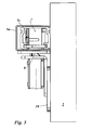
- the door 1 is designed as a stop swivel wing with the door axis A. It is driven via a Gleitarmesch professioner 5 in the closing direction.
- the Gleitarmesch professioner 5 has a door closer housing 5 g, which is mounted on the door leaf 1.
- a conventional door closer mechanism can be mounted, that is, a closing spring, which cooperates with a closer in the door closer housing 5g closer shaft 5w.
- a hydraulic piston-cylinder device may be connected, which is also in the Door closer housing 5g is added.
- the closer shaft 5w is rotatably connected to a power transmitting sliding arm 5k.
- the free end of the slide arm 5k has a trained as a roller or sliding block slider 5kg, which is guided linearly displaceable in a mounted on the door frame 3 slide 5s.
- the Gleitarmtsch deviser 5 is designed as a resting door closer.
- the door closer housing 5g is mounted resting on the door leaf 1 in the upper door near area in the position of the standard hole pattern provided in the door leaf with the interposition of a mounting plate 10.
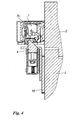
- the mounting plate 10 has a Mosachsenfernen section on which a resilient latch 6 is mounted, which cooperates with an electrically switchable door opener 7, which is mounted in the stationary door frame mounted on the mounted slide 5s, in a position the lock latch 6 from above over here (see Figures 3 and 4 ).
- the resilient latch 6 may also be provided a hook latch device.
- the door opener 7 is designed as escape door opener, for example with a structure as in DE 42 29 239 C1 described. The door opener 7 is received in the slide rail 5s outside the range of movement of the slider of the slide arm 5k, in a position located beyond the movement path of the slider, away from the end position occupied by the slider in the closed position of the door ,
- the slide rail 5s is in the in the Figures 3 and 4 illustrated case formed as a profile body having an upper profile chamber and a lower profile chamber.
- the other profile chamber is open at the bottom and takes as a guide to the slider of the sliding arm 5k.
- the upper profile chamber is designed to receive further components of the Gleitarmtsch consumers, For example, for an electrical locking device, which cooperates with the slider of the sliding arm 5k to hold the slider in an open position to stop, for the purpose of determining the door leaf in an open position.
- the door opener 7 is accommodated in the upper and lower profile chambers, in an extension section of the slide rail outside the movement path of the slider.
- the slide has in the in the Figures 3 and 4 Case shown still a cover 5a, which is plugged as a cover housing on the profile body of the slide 5s to optically cover the profile body over its entire length.
- the electric door opener 7 is controlled by a terminal 8 which is fixedly installed in the wall adjacent to the vertical bar of the fixed door frame 2.
- the terminal 8 has an electrical control device with a emergency button 8a. Furthermore, the terminal has a key switch 8b.
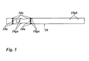
- the mounting plate 10, on which the door closer housing 5g is mounted is extended towards the plate side remote from conventional mounting plates. In this extension section, the resilient latch 6 is mounted.
- the mounting plate 10 has mounting holes 10 a, which are aligned with the standard hole in the upper near-door area of the door leaf 1 and 1 mounting screws for mounting on the door, which are screwed to secure the mounting plate 10 on the door 1 in the standard holes of the door leaf.
- the mounting plate on separate threaded holes 10ga, in which the mounting screws of the door closer housing 5g are screwed to fasten the door closer housing on the mounting plate.
- the mounting plate 10 is screwed in the illustrated case in its door near section, in which the bores are formed for the attachment of the door closer housing, in the standard boreholes with the door leaf.
- the mounting plate 10 is glued in the extension portion with the door leaf. The bond may be formed to extend only in the off-plate portion of the mounting plate on which the latch is mounted.
- the adhesive connection can also extend into other portions of the mounting plate, even down to the door near the area in which the mounting of the mounting plate is done by screwing in the standard drilling pattern of the door leaf.
- adhesive attachment on the door and a screw fastening may be provided to secure the mounting plate in the region of the extension portion on the door leaf.
- the position of the door opener 7 relative to the position of the latch 6 may be designed adjustable. It can be provided that in the direction of the door width of the door opener 7 in the slide 5s is adjustable. In Door opening direction, ie in the direction perpendicular to the door opening, an adjustment of the position of the latch 6 may be provided by shims during assembly of the latch. Additionally or alternatively, a door opener trap adjustment, eg with Aufschraub published, preferably as in DE 10 2004 037 827 A1 described, or with eccentric, preferably as in EP 0 841 474 A1 described, be provided.
- an electromechanical or electro-hydraulic Gleitarmtantrieb be provided, via which the door is driven both to open or to close.
- the Gleitarmtantrieb is mounted in the same way as the Gleitarmcschtechnik 5 with its drive housing on the door leaf 1 via the mounting plate 10. Its drive shaft is connected to the guided in the slide 5s sliding arm 5k.
- an electromotive lock is mounted instead of the electrically switchable door opener 7 in the slide rail 5s.
- the latch bolt 6 is mounted on the door, on the extension portion of the mounting plate 10 in this case, a strike plate into which engages an electromotive bolt of the arranged in the slide electromotive lock in the closed position of the door.
- an electro-adhesive magnet is arranged on the door frame side instead of the electric door opener mounted in the slide rail 5s. It is preferably mounted in a housing in which the slide rail 5s is arranged. This housing thus forms a Common housing for the slide rail and for the electro-magnet.
- the electromagnet is in the same position as the electric strike in the FIGS. 1 to 4 assembled. It cooperates with a counter plate, which is mounted on the wing side instead of the resilient latch 6. This in the closed position with the magnet cooperating counter-plate is in the same way as the latch in the FIGS. 1 to 4 mounted on the extension portion of the mounting plate 10.
- the door device shown in the figures is, as mentioned above, an escape door lock.
- the door leaf In the normal operating state of the escape door device, the door leaf is closed, ie the door leaf is in the closed position as in the FIGS. 1 to 4 shown.
- the arranged in the slide electric door opener 7 is connected in the blocking position. Detected in the locked position door latch holds the engaging with her lock latch 6 in her facing away from the door vertical vertical stop surface in abutment, as in FIG. 4 shown.
- the electric door opener 7 is switched by pressing the emergency button in its release position. The door opener trap is thus released, so that the lock latch 6 is no longer locked by the door opener latch of the door opener and the door 1 can be opened.
- the manually swung in the opening direction door leaf is automatically closed again from its open position under the action of the door closer by the closing spring, which is stretched when the door is opened.
- the resilient latch 6 is over their facing the door slope on the door latch latch or a suppressed with the door opener housing or another frame-fixed stop when the door 1 enters the closed position.
- the door opener which is in the blocking position in the normal operating state holds then again on the locked door latch trap the door in its closed position.
- the housing of the door drive 5 and the counter-device 6 are summarized as overlying common unit, wherein the mounting plate 10 connects these two components as a force-transmitting.
- the mounting plate 10 connects these two components as a force-transmitting.
- the components are also combined on the frame side to form a unit, namely the slide rail 5s and the locking device 7.
- the locking device 7 is received in the slide 5s supporting in a chamber of the slide.
- the slide rail and the locking device are mounted only on a common carrier plate or common mounting plate, which summarizes the slide rail and the locking device to a frame-side unit in a force-transmitting manner. Also in this frame-side unit even more components can be added.
Landscapes
- Physics & Mathematics (AREA)
- Electromagnetism (AREA)
- Engineering & Computer Science (AREA)
- Mechanical Engineering (AREA)
- Power-Operated Mechanisms For Wings (AREA)
- Wing Frames And Configurations (AREA)
Applications Claiming Priority (1)
| Application Number | Priority Date | Filing Date | Title |
|---|---|---|---|
| DE102011007975.0A DE102011007975B4 (de) | 2011-01-04 | 2011-01-04 | Türbeschlagseinrichtung |
Publications (3)
| Publication Number | Publication Date |
|---|---|
| EP2472042A2 true EP2472042A2 (fr) | 2012-07-04 |
| EP2472042A3 EP2472042A3 (fr) | 2013-12-18 |
| EP2472042B1 EP2472042B1 (fr) | 2016-08-31 |
Family
ID=45491378
Family Applications (1)
| Application Number | Title | Priority Date | Filing Date |
|---|---|---|---|
| EP12000046.8A Active EP2472042B1 (fr) | 2011-01-04 | 2012-01-04 | Dispositif de ferrure de porte |
Country Status (4)
| Country | Link |
|---|---|
| EP (1) | EP2472042B1 (fr) |
| DE (1) | DE102011007975B4 (fr) |
| ES (1) | ES2605103T3 (fr) |
| PL (1) | PL2472042T3 (fr) |
Cited By (6)
| Publication number | Priority date | Publication date | Assignee | Title |
|---|---|---|---|---|
| WO2016113394A1 (fr) * | 2015-01-16 | 2016-07-21 | Assa Abloy Sicherheitstechnik Gmbh | Dispositif de sécurité pour fixer une porte dans des voies d'évacuation et de sauvetage |
| WO2016113431A1 (fr) * | 2015-01-18 | 2016-07-21 | Assa Abloy Sicherheitstechnik Gmbh | Mécanisme d'entraînement de porte composé d'un entraînement principal et d'un entraînement auxiliaire |
| DE102015000513C5 (de) | 2015-01-18 | 2021-12-30 | Assa Abloy Sicherheitstechnik Gmbh | Türantriebseinrichtung mit Hauptantrieb und Hilfsantrieb |
| US20230407677A1 (en) * | 2022-06-15 | 2023-12-21 | Hanchett Entry System, Inc. | Modular surface mounted electric strike |
| EP4556660A3 (fr) * | 2022-06-15 | 2025-08-06 | Hanchett Entry Systems, Inc. | Gâche électrique montée en surface |
| US12601201B2 (en) | 2022-06-15 | 2026-04-14 | Hanchett Entry Systems, Inc. | Surface mounted electric strike |
Families Citing this family (1)
| Publication number | Priority date | Publication date | Assignee | Title |
|---|---|---|---|---|
| CN106968528B (zh) * | 2017-04-25 | 2022-08-09 | 亚萨合莱国强(山东)五金科技有限公司 | 一种外开双向传动器 |
Family Cites Families (8)
| Publication number | Priority date | Publication date | Assignee | Title |
|---|---|---|---|---|
| DE9102788U1 (de) * | 1991-03-08 | 1991-06-06 | Geze GmbH & Co, 7250 Leonberg | Pendeltür |
| DE4229239C1 (fr) * | 1992-09-02 | 1993-09-23 | Fritz Fuss Gmbh & Co, 7470 Albstadt, De | |
| DE9213550U1 (de) * | 1992-10-08 | 1992-12-17 | GEZE GmbH, 71229 Leonberg | Türbeschlag mit Türschließer und Zuhalteeinrichtung |
| DE19645964A1 (de) | 1996-11-07 | 1998-05-14 | Bayerische Motoren Werke Ag | Schaltbarer Tassenstößel für Gaswechselventile von Brennkraftmaschinen, insbesondere mit Zylinderabschaltung |
| DE19646490C2 (de) * | 1996-11-11 | 1999-01-21 | Fuss Fritz Gmbh & Co | Verstellbare Schwenkfalle für Türöffner |
| DE102004037827B4 (de) * | 2004-08-04 | 2007-01-11 | Assa Abloy Sicherheitstechnik Gmbh | Elektrischer Türöffner |
| DE102004053822B4 (de) * | 2004-11-04 | 2010-07-08 | Dorma Gmbh + Co. Kg | Profillose Ganzglasanlage |
| DE102007054460A1 (de) * | 2007-11-13 | 2009-05-14 | Dorma Gmbh + Co. Kg | Türantrieb mit modularem Aufbau |
-
2011
- 2011-01-04 DE DE102011007975.0A patent/DE102011007975B4/de not_active Expired - Fee Related
-
2012
- 2012-01-04 ES ES12000046.8T patent/ES2605103T3/es active Active
- 2012-01-04 PL PL12000046T patent/PL2472042T3/pl unknown
- 2012-01-04 EP EP12000046.8A patent/EP2472042B1/fr active Active
Cited By (10)
| Publication number | Priority date | Publication date | Assignee | Title |
|---|---|---|---|---|
| WO2016113394A1 (fr) * | 2015-01-16 | 2016-07-21 | Assa Abloy Sicherheitstechnik Gmbh | Dispositif de sécurité pour fixer une porte dans des voies d'évacuation et de sauvetage |
| EP3245371B1 (fr) | 2015-01-16 | 2020-01-15 | Assa Abloy Sicherheitstechnik GmbH | Dispositif de sécurité pour sécuriser une porte dans les voies d'évacuation et de sauvetage |
| WO2016113431A1 (fr) * | 2015-01-18 | 2016-07-21 | Assa Abloy Sicherheitstechnik Gmbh | Mécanisme d'entraînement de porte composé d'un entraînement principal et d'un entraînement auxiliaire |
| DE102015000513C5 (de) | 2015-01-18 | 2021-12-30 | Assa Abloy Sicherheitstechnik Gmbh | Türantriebseinrichtung mit Hauptantrieb und Hilfsantrieb |
| US20230407677A1 (en) * | 2022-06-15 | 2023-12-21 | Hanchett Entry System, Inc. | Modular surface mounted electric strike |
| US11885154B2 (en) * | 2022-06-15 | 2024-01-30 | Hanchett Entry Systems, Inc. | Modular surface mounted electric strike |
| EP4556660A3 (fr) * | 2022-06-15 | 2025-08-06 | Hanchett Entry Systems, Inc. | Gâche électrique montée en surface |
| US12509915B2 (en) | 2022-06-15 | 2025-12-30 | Hanchett Entry Systems, Inc. | Surface mounted electric strike |
| US12559978B2 (en) | 2022-06-15 | 2026-02-24 | Hanchett Entry Systems, Inc. | Modular surface mounted electric strike |
| US12601201B2 (en) | 2022-06-15 | 2026-04-14 | Hanchett Entry Systems, Inc. | Surface mounted electric strike |
Also Published As
| Publication number | Publication date |
|---|---|
| DE102011007975A1 (de) | 2012-07-05 |
| PL2472042T3 (pl) | 2017-02-28 |
| EP2472042B1 (fr) | 2016-08-31 |
| EP2472042A3 (fr) | 2013-12-18 |
| DE102011007975B4 (de) | 2015-04-02 |
| ES2605103T3 (es) | 2017-03-13 |
Similar Documents
| Publication | Publication Date | Title |
|---|---|---|
| EP2459824B1 (fr) | Dispositif de fermeture de porte | |
| EP2472042B1 (fr) | Dispositif de ferrure de porte | |
| EP2054573B1 (fr) | Dispositif d'ouverture pour des parties de meuble à mobilité relative | |
| EP2542742B1 (fr) | Dispositif d'ouverture de porte pourvu d'un dispositif de deverrouillage | |
| DE102012111085B4 (de) | Türöffner | |
| DE202012002502U1 (de) | Vorrichtung zur Unterstützung und Erleichterung des Kipp-Öffnens und -Schließens für ein Fenster oder eine Tür | |
| EP2472041B1 (fr) | Plaque de montage | |
| EP2752539B2 (fr) | Crémone espagnolette | |
| EP0324075B1 (fr) | Dispositif de commande de la séquence de fermeture de portes à deux battants | |
| DE102005063645B3 (de) | Türeinrichtung mit einer Türöffneranordnung | |
| EP3247854B1 (fr) | Porte comprenant un entraînement de porte avec un entraînement principal et un entraînement auxiliaire et éléments fonctionnels supplémentaires | |
| DE19540505A1 (de) | Türschließer mit selbsttätiger Schließbewegung und verdeckt angeordnetem Schließergehäuse | |
| DE102016100956A1 (de) | Türantrieb mit Haupt- und Hilfsantrieb und Zusatzfunktionskomponenten | |
| DE19717959A1 (de) | Vorrichtung zum Öffnen, Schließen oder Dämpfen eines Flügels einer Tür, eines Fensters oder dergleichen | |
| DE19700859A1 (de) | Tür- oder Fensteranlage mit einer Verriegelungsvorrichtung | |
| DE102012200640A1 (de) | Antriebsvorrichtung für eine gemeinsame Betätigung eines Zentralverschlusses und des Flügels eines Fensters oder einer Türe | |
| DE19857432B4 (de) | Schließeinrichtung für Gebäudetüren oder Gebäudefenster | |
| DE102006013086A1 (de) | Beschlag für ein Fenster oder eine Tür | |
| EP3211165A1 (fr) | Dispositif d'ouverture d'un vantail oscillo-battant d'une fenêtre ou d'une porte destiné au basculement motorisé et à la rotation et au basculement manuels | |
| EP1544396B1 (fr) | Coordinateur de fermeture de portes à double battants | |
| EP1790805B1 (fr) | Mécanisme d'actionnement à levier pour une crémone | |
| DE102012106191B4 (de) | Vorspannbauteil für eine Fenster- oder Türvorrichtung und Fenster- oder Türvorrichtung | |
| DE202009013076U1 (de) | Schließfolgeregelung für eine Schiebe-Drehtür, insbesondere für Brandschutzzwecke | |
| EP3626918B1 (fr) | Ferrure pour une fenêtre, fenêtre | |
| EP0685621A1 (fr) | Dispositif de verrouillage pour porte à actionnement automatique |
Legal Events
| Date | Code | Title | Description |
|---|---|---|---|
| AK | Designated contracting states |
Kind code of ref document: A2 Designated state(s): AL AT BE BG CH CY CZ DE DK EE ES FI FR GB GR HR HU IE IS IT LI LT LU LV MC MK MT NL NO PL PT RO RS SE SI SK SM TR |
|
| AX | Request for extension of the european patent |
Extension state: BA ME |
|
| PUAI | Public reference made under article 153(3) epc to a published international application that has entered the european phase |
Free format text: ORIGINAL CODE: 0009012 |
|
| RAP1 | Party data changed (applicant data changed or rights of an application transferred) |
Owner name: ASSA ABLOY SICHERHEITSTECHNIK GMBH |
|
| RIN1 | Information on inventor provided before grant (corrected) |
Inventor name: SCHNEKENBURGER, RUDOLF Inventor name: KAESTLE, KARL HEINZ Inventor name: GUTMANN, GERHARD Inventor name: ROTENHAGEN, ULRICH |
|
| PUAL | Search report despatched |
Free format text: ORIGINAL CODE: 0009013 |
|
| AK | Designated contracting states |
Kind code of ref document: A3 Designated state(s): AL AT BE BG CH CY CZ DE DK EE ES FI FR GB GR HR HU IE IS IT LI LT LU LV MC MK MT NL NO PL PT RO RS SE SI SK SM TR |
|
| AX | Request for extension of the european patent |
Extension state: BA ME |
|
| RIC1 | Information provided on ipc code assigned before grant |
Ipc: E05F 3/22 20060101AFI20131112BHEP Ipc: E05B 47/00 20060101ALI20131112BHEP Ipc: E05C 19/16 20060101ALI20131112BHEP |
|
| 17P | Request for examination filed |
Effective date: 20140617 |
|
| RBV | Designated contracting states (corrected) |
Designated state(s): AL AT BE BG CH CY CZ DE DK EE ES FI FR GB GR HR HU IE IS IT LI LT LU LV MC MK MT NL NO PL PT RO RS SE SI SK SM TR |
|
| RIC1 | Information provided on ipc code assigned before grant |
Ipc: E05C 19/16 20060101ALI20141119BHEP Ipc: E05C 1/00 20060101ALN20141119BHEP Ipc: E05C 1/08 20060101ALN20141119BHEP Ipc: E05B 47/00 20060101AFI20141119BHEP Ipc: E05F 1/00 20060101ALN20141119BHEP Ipc: E05F 3/22 20060101ALI20141119BHEP |
|
| RIC1 | Information provided on ipc code assigned before grant |
Ipc: E05F 1/00 20060101ALN20141121BHEP Ipc: E05C 19/16 20060101ALI20141121BHEP Ipc: E05F 3/22 20060101ALI20141121BHEP Ipc: E05C 1/00 20060101ALN20141121BHEP Ipc: E05B 47/00 20060101AFI20141121BHEP Ipc: E05C 1/08 20060101ALN20141121BHEP |
|
| 17Q | First examination report despatched |
Effective date: 20141219 |
|
| REG | Reference to a national code |
Ref country code: DE Ref legal event code: R079 Ref document number: 502012008084 Country of ref document: DE Free format text: PREVIOUS MAIN CLASS: E05F0003220000 Ipc: E05B0047000000 |
|
| GRAP | Despatch of communication of intention to grant a patent |
Free format text: ORIGINAL CODE: EPIDOSNIGR1 |
|
| INTG | Intention to grant announced |
Effective date: 20160324 |
|
| RIC1 | Information provided on ipc code assigned before grant |
Ipc: E05F 3/22 20060101ALI20160315BHEP Ipc: E05F 1/00 20060101ALN20160315BHEP Ipc: E05C 19/16 20060101ALI20160315BHEP Ipc: E05B 47/00 20060101AFI20160315BHEP Ipc: E05C 1/00 20060101ALN20160315BHEP Ipc: E05C 1/08 20060101ALN20160315BHEP Ipc: E05B 9/08 20060101ALI20160315BHEP |
|
| GRAS | Grant fee paid |
Free format text: ORIGINAL CODE: EPIDOSNIGR3 |
|
| GRAA | (expected) grant |
Free format text: ORIGINAL CODE: 0009210 |
|
| AK | Designated contracting states |
Kind code of ref document: B1 Designated state(s): AL AT BE BG CH CY CZ DE DK EE ES FI FR GB GR HR HU IE IS IT LI LT LU LV MC MK MT NL NO PL PT RO RS SE SI SK SM TR |
|
| REG | Reference to a national code |
Ref country code: CH Ref legal event code: EP Ref country code: GB Ref legal event code: FG4D Free format text: NOT ENGLISH |
|
| REG | Reference to a national code |
Ref country code: IE Ref legal event code: FG4D Free format text: LANGUAGE OF EP DOCUMENT: GERMAN |
|
| REG | Reference to a national code |
Ref country code: DE Ref legal event code: R096 Ref document number: 502012008084 Country of ref document: DE |
|
| REG | Reference to a national code |
Ref country code: AT Ref legal event code: REF Ref document number: 825128 Country of ref document: AT Kind code of ref document: T Effective date: 20161015 |
|
| REG | Reference to a national code |
Ref country code: NL Ref legal event code: FP |
|
| REG | Reference to a national code |
Ref country code: SE Ref legal event code: TRGR |
|
| REG | Reference to a national code |
Ref country code: LT Ref legal event code: MG4D |
|
| REG | Reference to a national code |
Ref country code: FR Ref legal event code: PLFP Year of fee payment: 6 |
|
| PG25 | Lapsed in a contracting state [announced via postgrant information from national office to epo] |
Ref country code: LT Free format text: LAPSE BECAUSE OF FAILURE TO SUBMIT A TRANSLATION OF THE DESCRIPTION OR TO PAY THE FEE WITHIN THE PRESCRIBED TIME-LIMIT Effective date: 20160831 Ref country code: NO Free format text: LAPSE BECAUSE OF FAILURE TO SUBMIT A TRANSLATION OF THE DESCRIPTION OR TO PAY THE FEE WITHIN THE PRESCRIBED TIME-LIMIT Effective date: 20161130 Ref country code: HR Free format text: LAPSE BECAUSE OF FAILURE TO SUBMIT A TRANSLATION OF THE DESCRIPTION OR TO PAY THE FEE WITHIN THE PRESCRIBED TIME-LIMIT Effective date: 20160831 Ref country code: RS Free format text: LAPSE BECAUSE OF FAILURE TO SUBMIT A TRANSLATION OF THE DESCRIPTION OR TO PAY THE FEE WITHIN THE PRESCRIBED TIME-LIMIT Effective date: 20160831 |
|
| PG25 | Lapsed in a contracting state [announced via postgrant information from national office to epo] |
Ref country code: GR Free format text: LAPSE BECAUSE OF FAILURE TO SUBMIT A TRANSLATION OF THE DESCRIPTION OR TO PAY THE FEE WITHIN THE PRESCRIBED TIME-LIMIT Effective date: 20161201 Ref country code: LV Free format text: LAPSE BECAUSE OF FAILURE TO SUBMIT A TRANSLATION OF THE DESCRIPTION OR TO PAY THE FEE WITHIN THE PRESCRIBED TIME-LIMIT Effective date: 20160831 |
|
| REG | Reference to a national code |
Ref country code: ES Ref legal event code: FG2A Ref document number: 2605103 Country of ref document: ES Kind code of ref document: T3 Effective date: 20170313 |
|
| PG25 | Lapsed in a contracting state [announced via postgrant information from national office to epo] |
Ref country code: RO Free format text: LAPSE BECAUSE OF FAILURE TO SUBMIT A TRANSLATION OF THE DESCRIPTION OR TO PAY THE FEE WITHIN THE PRESCRIBED TIME-LIMIT Effective date: 20160831 Ref country code: EE Free format text: LAPSE BECAUSE OF FAILURE TO SUBMIT A TRANSLATION OF THE DESCRIPTION OR TO PAY THE FEE WITHIN THE PRESCRIBED TIME-LIMIT Effective date: 20160831 |
|
| PG25 | Lapsed in a contracting state [announced via postgrant information from national office to epo] |
Ref country code: SK Free format text: LAPSE BECAUSE OF FAILURE TO SUBMIT A TRANSLATION OF THE DESCRIPTION OR TO PAY THE FEE WITHIN THE PRESCRIBED TIME-LIMIT Effective date: 20160831 Ref country code: SM Free format text: LAPSE BECAUSE OF FAILURE TO SUBMIT A TRANSLATION OF THE DESCRIPTION OR TO PAY THE FEE WITHIN THE PRESCRIBED TIME-LIMIT Effective date: 20160831 Ref country code: CZ Free format text: LAPSE BECAUSE OF FAILURE TO SUBMIT A TRANSLATION OF THE DESCRIPTION OR TO PAY THE FEE WITHIN THE PRESCRIBED TIME-LIMIT Effective date: 20160831 Ref country code: BE Free format text: LAPSE BECAUSE OF NON-PAYMENT OF DUE FEES Effective date: 20170131 Ref country code: PT Free format text: LAPSE BECAUSE OF FAILURE TO SUBMIT A TRANSLATION OF THE DESCRIPTION OR TO PAY THE FEE WITHIN THE PRESCRIBED TIME-LIMIT Effective date: 20170102 Ref country code: DK Free format text: LAPSE BECAUSE OF FAILURE TO SUBMIT A TRANSLATION OF THE DESCRIPTION OR TO PAY THE FEE WITHIN THE PRESCRIBED TIME-LIMIT Effective date: 20160831 Ref country code: BG Free format text: LAPSE BECAUSE OF FAILURE TO SUBMIT A TRANSLATION OF THE DESCRIPTION OR TO PAY THE FEE WITHIN THE PRESCRIBED TIME-LIMIT Effective date: 20161130 |
|
| REG | Reference to a national code |
Ref country code: DE Ref legal event code: R097 Ref document number: 502012008084 Country of ref document: DE |
|
| PLBE | No opposition filed within time limit |
Free format text: ORIGINAL CODE: 0009261 |
|
| STAA | Information on the status of an ep patent application or granted ep patent |
Free format text: STATUS: NO OPPOSITION FILED WITHIN TIME LIMIT |
|
| 26N | No opposition filed |
Effective date: 20170601 |
|
| PG25 | Lapsed in a contracting state [announced via postgrant information from national office to epo] |
Ref country code: SI Free format text: LAPSE BECAUSE OF FAILURE TO SUBMIT A TRANSLATION OF THE DESCRIPTION OR TO PAY THE FEE WITHIN THE PRESCRIBED TIME-LIMIT Effective date: 20160831 |
|
| REG | Reference to a national code |
Ref country code: CH Ref legal event code: PL |
|
| PG25 | Lapsed in a contracting state [announced via postgrant information from national office to epo] |
Ref country code: MC Free format text: LAPSE BECAUSE OF FAILURE TO SUBMIT A TRANSLATION OF THE DESCRIPTION OR TO PAY THE FEE WITHIN THE PRESCRIBED TIME-LIMIT Effective date: 20160831 |
|
| PG25 | Lapsed in a contracting state [announced via postgrant information from national office to epo] |
Ref country code: CH Free format text: LAPSE BECAUSE OF NON-PAYMENT OF DUE FEES Effective date: 20170131 Ref country code: LI Free format text: LAPSE BECAUSE OF NON-PAYMENT OF DUE FEES Effective date: 20170131 |
|
| REG | Reference to a national code |
Ref country code: IE Ref legal event code: MM4A |
|
| PG25 | Lapsed in a contracting state [announced via postgrant information from national office to epo] |
Ref country code: LU Free format text: LAPSE BECAUSE OF NON-PAYMENT OF DUE FEES Effective date: 20170104 |
|
| REG | Reference to a national code |
Ref country code: FR Ref legal event code: PLFP Year of fee payment: 7 |
|
| PGFP | Annual fee paid to national office [announced via postgrant information from national office to epo] |
Ref country code: FR Payment date: 20171229 Year of fee payment: 7 Ref country code: NL Payment date: 20171213 Year of fee payment: 7 |
|
| REG | Reference to a national code |
Ref country code: BE Ref legal event code: MM Effective date: 20170131 |
|
| PG25 | Lapsed in a contracting state [announced via postgrant information from national office to epo] |
Ref country code: IE Free format text: LAPSE BECAUSE OF NON-PAYMENT OF DUE FEES Effective date: 20170104 |
|
| PGFP | Annual fee paid to national office [announced via postgrant information from national office to epo] |
Ref country code: PL Payment date: 20171220 Year of fee payment: 7 |
|
| REG | Reference to a national code |
Ref country code: AT Ref legal event code: MM01 Ref document number: 825128 Country of ref document: AT Kind code of ref document: T Effective date: 20170104 |
|
| PGFP | Annual fee paid to national office [announced via postgrant information from national office to epo] |
Ref country code: FI Payment date: 20180110 Year of fee payment: 7 Ref country code: GB Payment date: 20180103 Year of fee payment: 7 Ref country code: ES Payment date: 20180201 Year of fee payment: 7 |
|
| PG25 | Lapsed in a contracting state [announced via postgrant information from national office to epo] |
Ref country code: AT Free format text: LAPSE BECAUSE OF NON-PAYMENT OF DUE FEES Effective date: 20170104 |
|
| PGFP | Annual fee paid to national office [announced via postgrant information from national office to epo] |
Ref country code: IT Payment date: 20180122 Year of fee payment: 7 Ref country code: SE Payment date: 20180111 Year of fee payment: 7 Ref country code: TR Payment date: 20180102 Year of fee payment: 7 |
|
| PG25 | Lapsed in a contracting state [announced via postgrant information from national office to epo] |
Ref country code: MT Free format text: LAPSE BECAUSE OF FAILURE TO SUBMIT A TRANSLATION OF THE DESCRIPTION OR TO PAY THE FEE WITHIN THE PRESCRIBED TIME-LIMIT Effective date: 20160831 |
|
| PG25 | Lapsed in a contracting state [announced via postgrant information from national office to epo] |
Ref country code: AL Free format text: LAPSE BECAUSE OF FAILURE TO SUBMIT A TRANSLATION OF THE DESCRIPTION OR TO PAY THE FEE WITHIN THE PRESCRIBED TIME-LIMIT Effective date: 20160831 |
|
| PG25 | Lapsed in a contracting state [announced via postgrant information from national office to epo] |
Ref country code: HU Free format text: LAPSE BECAUSE OF FAILURE TO SUBMIT A TRANSLATION OF THE DESCRIPTION OR TO PAY THE FEE WITHIN THE PRESCRIBED TIME-LIMIT; INVALID AB INITIO Effective date: 20120104 |
|
| REG | Reference to a national code |
Ref country code: NL Ref legal event code: MM Effective date: 20190201 |
|
| GBPC | Gb: european patent ceased through non-payment of renewal fee |
Effective date: 20190104 |
|
| PG25 | Lapsed in a contracting state [announced via postgrant information from national office to epo] |
Ref country code: SE Free format text: LAPSE BECAUSE OF NON-PAYMENT OF DUE FEES Effective date: 20190105 Ref country code: CY Free format text: LAPSE BECAUSE OF NON-PAYMENT OF DUE FEES Effective date: 20160831 Ref country code: FR Free format text: LAPSE BECAUSE OF NON-PAYMENT OF DUE FEES Effective date: 20190131 Ref country code: FI Free format text: LAPSE BECAUSE OF NON-PAYMENT OF DUE FEES Effective date: 20190104 Ref country code: NL Free format text: LAPSE BECAUSE OF NON-PAYMENT OF DUE FEES Effective date: 20190201 |
|
| PG25 | Lapsed in a contracting state [announced via postgrant information from national office to epo] |
Ref country code: MK Free format text: LAPSE BECAUSE OF FAILURE TO SUBMIT A TRANSLATION OF THE DESCRIPTION OR TO PAY THE FEE WITHIN THE PRESCRIBED TIME-LIMIT Effective date: 20160831 |
|
| PG25 | Lapsed in a contracting state [announced via postgrant information from national office to epo] |
Ref country code: GB Free format text: LAPSE BECAUSE OF NON-PAYMENT OF DUE FEES Effective date: 20190104 |
|
| PG25 | Lapsed in a contracting state [announced via postgrant information from national office to epo] |
Ref country code: IT Free format text: LAPSE BECAUSE OF NON-PAYMENT OF DUE FEES Effective date: 20190104 |
|
| REG | Reference to a national code |
Ref country code: ES Ref legal event code: FD2A Effective date: 20200309 |
|
| PG25 | Lapsed in a contracting state [announced via postgrant information from national office to epo] |
Ref country code: ES Free format text: LAPSE BECAUSE OF NON-PAYMENT OF DUE FEES Effective date: 20190105 |
|
| PG25 | Lapsed in a contracting state [announced via postgrant information from national office to epo] |
Ref country code: IS Free format text: LAPSE BECAUSE OF FAILURE TO SUBMIT A TRANSLATION OF THE DESCRIPTION OR TO PAY THE FEE WITHIN THE PRESCRIBED TIME-LIMIT Effective date: 20161231 |
|
| PG25 | Lapsed in a contracting state [announced via postgrant information from national office to epo] |
Ref country code: TR Free format text: LAPSE BECAUSE OF NON-PAYMENT OF DUE FEES Effective date: 20190104 |
|
| PG25 | Lapsed in a contracting state [announced via postgrant information from national office to epo] |
Ref country code: PL Free format text: LAPSE BECAUSE OF NON-PAYMENT OF DUE FEES Effective date: 20190104 |
|
| PGFP | Annual fee paid to national office [announced via postgrant information from national office to epo] |
Ref country code: DE Payment date: 20251210 Year of fee payment: 15 |