EP2472090A2 - Moteur de turbine à gaz comprenant un système pour augmenter la poussée - Google Patents
Moteur de turbine à gaz comprenant un système pour augmenter la poussée Download PDFInfo
- Publication number
- EP2472090A2 EP2472090A2 EP11250948A EP11250948A EP2472090A2 EP 2472090 A2 EP2472090 A2 EP 2472090A2 EP 11250948 A EP11250948 A EP 11250948A EP 11250948 A EP11250948 A EP 11250948A EP 2472090 A2 EP2472090 A2 EP 2472090A2
- Authority
- EP
- European Patent Office
- Prior art keywords
- fluid
- exhaust flow
- gas turbine
- turbine engine
- operative
- Prior art date
- Legal status (The legal status is an assumption and is not a legal conclusion. Google has not performed a legal analysis and makes no representation as to the accuracy of the status listed.)
- Withdrawn
Links
- 230000003416 augmentation Effects 0.000 title claims abstract description 27
- 239000000446 fuel Substances 0.000 claims abstract description 14
- 239000012530 fluid Substances 0.000 claims description 127
- 238000004891 communication Methods 0.000 claims description 34
- 238000011144 upstream manufacturing Methods 0.000 claims description 18
- 239000007788 liquid Substances 0.000 claims description 4
- 239000007789 gas Substances 0.000 description 26
- 238000002485 combustion reaction Methods 0.000 description 16
- 230000008901 benefit Effects 0.000 description 3
- 238000012986 modification Methods 0.000 description 3
- 230000004048 modification Effects 0.000 description 3
- 230000003190 augmentative effect Effects 0.000 description 2
- 230000004075 alteration Effects 0.000 description 1
- 238000004200 deflagration Methods 0.000 description 1
- 238000005474 detonation Methods 0.000 description 1
- 238000005516 engineering process Methods 0.000 description 1
- 239000000284 extract Substances 0.000 description 1
- 238000000034 method Methods 0.000 description 1
- 230000001737 promoting effect Effects 0.000 description 1
Images

Classifications
-
- F—MECHANICAL ENGINEERING; LIGHTING; HEATING; WEAPONS; BLASTING
- F02—COMBUSTION ENGINES; HOT-GAS OR COMBUSTION-PRODUCT ENGINE PLANTS
- F02K—JET-PROPULSION PLANTS
- F02K3/00—Plants including a gas turbine driving a compressor or a ducted fan
- F02K3/08—Plants including a gas turbine driving a compressor or a ducted fan with supplementary heating of the working fluid; Control thereof
- F02K3/10—Plants including a gas turbine driving a compressor or a ducted fan with supplementary heating of the working fluid; Control thereof by after-burners
-
- F—MECHANICAL ENGINEERING; LIGHTING; HEATING; WEAPONS; BLASTING
- F23—COMBUSTION APPARATUS; COMBUSTION PROCESSES
- F23R—GENERATING COMBUSTION PRODUCTS OF HIGH PRESSURE OR HIGH VELOCITY, e.g. GAS-TURBINE COMBUSTION CHAMBERS
- F23R3/00—Continuous combustion chambers using liquid or gaseous fuel
- F23R3/02—Continuous combustion chambers using liquid or gaseous fuel characterised by the air-flow or gas-flow configuration
- F23R3/16—Continuous combustion chambers using liquid or gaseous fuel characterised by the air-flow or gas-flow configuration with devices inside the flame tube or the combustion chamber to influence the air or gas flow
- F23R3/18—Flame stabilising means, e.g. flame holders for after-burners of jet-propulsion plants
- F23R3/20—Flame stabilising means, e.g. flame holders for after-burners of jet-propulsion plants incorporating fuel injection means
Definitions
- the present invention relates to gas turbine engines, and more particularly, to gas turbine engine thrust augmentation systems.
- One embodiment of the present invention is a unique gas turbine engine having a unique thrust augmentation system.
- Other embodiments include apparatuses, systems, devices, hardware, methods, and combinations for thrust augmented gas turbine engines. Further embodiments, forms, features, aspects, benefits, and advantages of the present application will become apparent from the description and figures provided herewith.
- gas turbine engine 10 is an aircraft propulsion power plant.
- gas turbine engine 10 is a multi-spool turbofan engine.
- gas turbine engine 10 may take other forms, and may be, for example, a single spool turbojet engine.
- gas turbine engine 10 includes a fan system 12, a bypass duct 14, a compressor system 16, a diffuser 18, a combustion system 20, a turbine system 22, a discharge duct 26 and a nozzle 28.
- Bypass duct 14 and compressor system 16 are in fluid communication with fan system 12.
- Diffuser 18 is in fluid communication with compressor system 16.
- Combustion system 20 is in fluid communication with diffuser 18.
- Turbine system 22 is in fluid communication with combustion system 20, and is operative to discharge a core exhaust flow.
- combustion system 20 includes a combustion liner (not shown) that contains a continuous combustion process.
- combustion system 20 may take other forms, and may be, for example, a wave rotor combustion system, a rotary valve combustion system, or a slinger combustion system, and may employ deflagration and/or detonation combustion processes.
- Fan system 12 includes a fan rotor system 30.
- fan rotor system 30 includes one or more rotors (not shown) that are powered by turbine system 22.
- Bypass duct 14 is operative to transmit a bypass flow generated by fan system 12 to nozzle 28.
- Compressor system 16 includes a compressor rotor system 32.
- compressor rotor system 32 includes one or more rotors (not shown) that are powered by turbine system 22.
- Each compressor rotor includes a plurality of compressor blades (not shown).
- Turbine system 22 includes a turbine rotor system 34.
- turbine rotor system 34 includes one or more rotors (not shown) operative to drive fan rotor system 30 and compressor rotor system 32.
- Each turbine rotor includes a plurality of turbine blades (not shown).
- Turbine rotor system 34 is drivingly coupled to compressor rotor system 32 and fan rotor system 30 via a shafting system 36.
- shafting system 36 includes a plurality of shafts that may rotate at the same or different speeds and directions. In some embodiments, only a single shaft may be employed.
- Turbine system 22 is operative to discharge an engine 10 core exhaust flow to nozzle 28.
- fan rotor system 30, compressor rotor system 32, turbine rotor system 34 and shafting system 36 rotate about an engine centerline 48. In other embodiments, all or parts of fan rotor system 30, compressor rotor system 32, turbine rotor system 34 and shafting system 36 may rotate about one or more other axes of rotation in addition to, or in place of, engine centerline 48.
- Turbine system 22 includes a turbine outlet 38 and a turbine outlet duct 40 extending from turbine outlet 38 toward nozzle 28.
- Discharge duct 26 extends between turbine outlet duct 40 and an inlet portion of engine nozzle 28.
- Discharge duct 26 is operative to direct bypass flow and core exhaust flow from a bypass duct discharge portion 42 and turbine outlet duct 40, respectively, into nozzle system 28.
- discharge duct 26 may be considered a part of nozzle 28.
- Nozzle 28 is in fluid communication with fan system 12 via bypass duct 14 and discharge duct 26.
- Nozzle system 28 is in fluid communication with turbine system 22 via turbine outlet duct 40 and discharge duct 26.
- Nozzle 28 is operative to receive the bypass flow from fan system 12, to receive the core exhaust flow from turbine system 22, and to discharge both via nozzle exit 28A as an engine exhaust flow, i.e., a thrust-producing flow.
- air is drawn into the inlet of fan 12 and pressurized by fan 12.
- Some of the air pressurized by fan 12 is directed into compressor system 16 as core flow, and some of the pressurized air is directed into bypass duct 14 as bypass flow, and is discharged into nozzle 28 via discharge duct 26.
- Compressor system 16 further pressurizes the portion of the air received therein from fan 12, which is then discharged into diffuser 18.
- Diffuser 18 reduces the velocity of the pressurized air, and directs the diffused core airflow into combustion system 20.
- Fuel is mixed with the pressurized air in combustion system 20, which is then combusted.
- the hot gases exiting combustion system 20 are directed into turbine system 22, which extracts energy in the form of mechanical shaft power sufficient to drive fan system 12 and compressor system 16 via shafting system 36.
- the core flow exiting turbine system 22 is directed along between turbine outlet duct 42 and engine tail cone 44 into discharge duct 26, along with the bypass flow from bypass duct 14.
- Discharge duct 26 is configured to receive the bypass flow and the core flow, and to discharge both as an engine exhaust flow into nozzle 28, e.g., for providing thrust, such as for aircraft propulsion.
- Engine 10 includes a thrust augmentation (afterburner) system 60 for providing increased thrust.
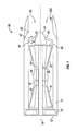
- Thrust augmentation system 60 includes a plurality of fluidic flameholders 62.
- Thrust augmentation system 60 is operative to augment the thrust output of engine 10 by adding fuel to the exhaust flow of engine 10 downstream of turbine system 22, and igniting the added fuel.
- the added fuel is ignited by igniters (not shown).
- the fuel may be ignited via auto-ignition or via other means. The combustion of the added fuel adds heat to the exhaust flow, thereby increasing the volume of the exhaust gases and hence increasing the velocity of the exhaust flow exiting nozzle exit 28A.
- Fluidic flameholders 62 are configured to hold flames during thrust augmentation operation, e.g., so that a continuous combustion process takes place.
- Flameholders 62 are referred to herein as "fluidic" flameholders because flameholders 62 employ a fluid to generate obstructions to exhaust flow, as opposed to a mechanical device forming an obstruction, such as in conventional flameholders.
- fluidic flameholders 62 are disposed downstream of turbine system 22 and upstream of nozzle exit 28A.
- Fluidic flameholders 62 include a flowpath structure 64, a fluid supply passage 66 and a plurality of fluid discharge openings 68.
- flowpath structure 64 may be disposed adjacent to the exhaust flow and/or may be disposed partially or fully within the exhaust flow.
- flowpath structure 64 extends radially inward of a turbine outlet duct 42, and is positioned downstream of turbine system 22, i.e., downstream of turbine outlet 38.
- flowpath structure 64 may be disposed in other locations, e.g., further downstream of turbine system 22, e.g., in discharge duct 26 and/or nozzle 28; or further upstream toward turbine outlet 38.
- flowpath structure 64 is configured as a strut that extends into the exhaust flow.
- flowpath structure 64 may take one or more other forms.
- flowpath structure 64 extends from turbine outlet duct 42 to tailcone 44.
- flowpath structure 64 may extend only part way between turbine outlet duct 42 and tailcone 44.
- flowpath structure 64 may be arranged otherwise, e.g., and may extend from other locations.
- Fluid supply passage 66 is in fluid communication with a pressurized fluid source (not shown), and is operative to supply fluid to fluid discharge openings 68.
- Fluid discharge openings 68 are in fluid communication with fluid supply passage 66 on one end, and with the exhaust flow on the other end. Fluid discharge openings 68 are operative to eject the fluid received from fluid supply passage 66 into the exhaust flow.
- the number and/or shape of fluid discharge openings 68 may vary with the needs of the application.
- the fluid employed by fluidic flameholder 62 is liquid fuel. In other embodiments, other fluids, including gases and/or liquids, and including or not including fuel may be employed.
- fluid supply passage 66 and fluid discharge openings 68 are positioned at an upstream end 70 of flowpath structure 64.
- fluid supply passage 66 and/or one or more fluid supply openings 68 may be positioned at a downstream end 72 of flowpath structure 64 and/or other locations on flowpath structure 64 in addition to or in place of upstream end 70.
- fluid discharge openings 68 are disposed on both sides of a centerline 74 of flowpath structure 64, and are operative to eject fluid on both sides of centerline 74.
- one or more fluid discharge openings 68 may be positioned on only one side of centerline 74, and may be operative to eject fluid on one or both sides of centerline 74.
- the fluid discharge openings 68 are configured to eject the fluid with a velocity component in a direction 76 opposite the direction 78 of the exhaust flow. In other embodiments, fluid discharge openings 68 may be configured to eject the fluid in any suitable direction.
- Fluidic flameholder 62 is operative to generate an obstruction to the exhaust flow by ejecting the fluid from flowpath structure 64 via fluid discharge openings 68, wherein the obstruction is configured to hold a flame during thrust augmentation operation of engine 10.
- fluidic flameholder 62 is configured to generate the obstruction in the form of a low pressure area 80 downstream of fluid discharge openings 68 by ejecting fuel 82 into the exhaust flow.
- the obstruction may take one or more other forms, e.g., a high pressure area.
- the obstruction or low pressure area 80 is configured to hold a flame during thrust augmentation operation.
- fluidic flameholder 62 is configured to generate the obstruction adjacent to downstream end 72 of flowpath structure 64.
- fluidic flameholder 62 may be configured to generate the obstruction in other locations near and/or spaced apart from flowpath structure 64.
- the size, shape and location of the obstruction or low pressure area 80 may vary with the application, and may be determined, for example, using commercially available computational fluid dynamics analysis software. Parameters that affect the size and location of the obstruction or low pressure area include, for example and without limitation, the type, density and viscosity of the fluid ejected from fluidic flameholder 62, as well as the pressure, temperature and velocity of the exhaust flow.
- Embodiments of the present invention include a gas turbine engine, comprising: a compressor; a combustor in fluid communication with the compressor; a turbine in fluid communication with the combustor and operative to discharge an exhaust flow; a nozzle in fluid communication with the turbine, wherein the nozzle includes a nozzle exit; and wherein the nozzle is operative to receive the exhaust flow from the turbine and to discharge the exhaust flow through the nozzle exit; and a thrust augmentation system, including a fluidic flameholder disposed downstream of the turbine and upstream of the nozzle exit, wherein the fluidic flameholder includes a flowpath structure disposed adjacent to the exhaust flow and/or at least partially within the exhaust flow; wherein the fluidic flameholder is operative to generate a low pressure area by ejecting a fluid from the flowpath structure into the exhaust flow, wherein the low pressure area is operative to hold a flame during thrust augmentation operation of the gas turbine engine.
- the flowpath structure includes a fluid supply passage for supplying the fluid and a fluid discharge opening for ejecting the fluid; wherein the fluid discharge opening is in fluid communication with both the fluid supply passage and the exhaust flow; wherein the fluid discharge opening is operative to eject the fluid into the exhaust flow.
- the flowpath structure is a strut extending at least partially into the exhaust flow.
- the ejected fluid is a liquid.
- the ejected fluid includes fuel.
- the ejected fluid is fuel.
- the gas turbine engine further comprises a plurality of fluid discharge openings disposed in the flowpath structure and operative to eject the fluid into the exhaust flow.
- the flowpath structure is configured as a strut having an upstream end and a downstream end; and wherein at least some of the fluid discharge openings are positioned at the upstream end of the strut.
- the strut has a downstream end, and wherein the low pressure area is disposed adjacent to the downstream end.
- Embodiments of the present invention include a gas turbine engine, comprising: a fan; a compressor in fluid communication with the fan; a combustor in fluid communication with the compressor; a turbine in fluid communication with the combustor and operative to discharge an exhaust flow; a bypass duct in fluid communication with the fan and operative to receive a bypass flow from the fan; a nozzle in fluid communication with the turbine and in fluid communication with the bypass duct, wherein the nozzle includes a nozzle exit; and wherein the nozzle is operative to receive the exhaust flow from the turbine and to receive the bypass flow from the fan and to discharge both through the nozzle exit; and a thrust augmentation system, including a fluidic flameholder disposed downstream of the turbine and upstream of the nozzle exit, wherein the fluidic flameholder includes a flowpath structure disposed adjacent to the exhaust flow and/or at least partially within the exhaust flow; wherein the fluidic flameholder is operative to generate an obstruction to the exhaust flow by ejecting a fluid from the flowpath structure into the exhaust flow
- the obstruction is in the form of a low pressure area operative to hold the flame during the thrust augmentation operation of the gas turbine engine.
- the flowpath structure includes a fluid discharge opening for ejecting the fluid.
- the obstruction is in the form of a low pressure area in the exhaust flow downstream of the fluid discharge opening.
- the gas turbine engine further comprises a plurality of fluid discharge openings disposed in the flowpath structure and operative to eject the fluid into the exhaust flow.
- the flowpath structure is configured as a strut having an upstream end and a downstream end; and wherein at least some of the fluid discharge openings are positioned at the upstream end of the strut.
- the strut has a downstream end, and wherein the obstruction is disposed adjacent to the downstream end.
- the flowpath structure has a centerline oriented in the direction of the exhaust flow; wherein at least one of the fluid discharge openings is oriented to eject the fluid on a first side of the centerline; and wherein at least another of the fluid discharge openings is oriented to eject the fluid on a second side of the centerline opposite the first side.
- At least one of the fluid discharge openings is configured to eject the fluid with a velocity component in a direction opposite to the direction of exhaust flow.
- Embodiments of the present invention include a gas turbine engine, comprising: a compressor; a combustor in fluid communication with the compressor; a turbine in fluid communication with the combustor and operative to discharge an exhaust flow; a nozzle in fluid communication with the turbine, wherein the nozzle includes a nozzle exit; and wherein the nozzle is operative to receive the exhaust flow from the turbine and to discharge the exhaust flow through the nozzle exit; and a thrust augmentation system, including means for holding a flame during thrust augmentation operation of the gas turbine engine, wherein the means for holding is disposed downstream of the turbine and upstream of the nozzle exit.
- the means for holding includes a fluid discharge opening configured to generate an obstruction to the exhaust flow by ejecting a fluid into the exhaust flow, wherein the obstruction is operative to hold the flame during thrust augmentation operation of the gas turbine engine.
Landscapes
- Engineering & Computer Science (AREA)
- Chemical & Material Sciences (AREA)
- Combustion & Propulsion (AREA)
- Mechanical Engineering (AREA)
- General Engineering & Computer Science (AREA)
- Supercharger (AREA)
- Structures Of Non-Positive Displacement Pumps (AREA)
Applications Claiming Priority (1)
| Application Number | Priority Date | Filing Date | Title |
|---|---|---|---|
| US201061428760P | 2010-12-30 | 2010-12-30 |
Publications (2)
| Publication Number | Publication Date |
|---|---|
| EP2472090A2 true EP2472090A2 (fr) | 2012-07-04 |
| EP2472090A3 EP2472090A3 (fr) | 2014-03-05 |
Family
ID=45478174
Family Applications (1)
| Application Number | Title | Priority Date | Filing Date |
|---|---|---|---|
| EP11250948.4A Withdrawn EP2472090A3 (fr) | 2010-12-30 | 2011-12-28 | Moteur de turbine à gaz comprenant un système pour augmenter la poussée |
Country Status (3)
| Country | Link |
|---|---|
| US (1) | US20120167550A1 (fr) |
| EP (1) | EP2472090A3 (fr) |
| JP (1) | JP2012140960A (fr) |
Cited By (3)
| Publication number | Priority date | Publication date | Assignee | Title |
|---|---|---|---|---|
| CN104879782A (zh) * | 2015-05-18 | 2015-09-02 | 西北工业大学 | 新型非对称火焰稳定器 |
| CN106765310A (zh) * | 2016-12-23 | 2017-05-31 | 中航空天发动机研究院有限公司 | 用于发动机燃烧室的带预掺混腔的火焰稳定器 |
| CN112577068A (zh) * | 2020-12-14 | 2021-03-30 | 西安鑫垚陶瓷复合材料有限公司 | 一种陶瓷基复合材料内锥体及其加工方法 |
Families Citing this family (4)
| Publication number | Priority date | Publication date | Assignee | Title |
|---|---|---|---|---|
| CN110081463A (zh) * | 2019-01-18 | 2019-08-02 | 西北工业大学 | 一种可预混带翼缘扰流结构的火焰稳定器 |
| KR102617459B1 (ko) * | 2021-01-19 | 2023-12-27 | 이재창 | 방출배기를 이용한 분사추진기관 |
| US12595751B1 (en) | 2021-01-19 | 2026-04-07 | Jae-Chang Lee | Jet-propelled engine using discharged exhaust gas |
| CN113551262B (zh) * | 2021-07-19 | 2022-06-14 | 南昌航空大学 | 一种带新月沙丘型面的支板火焰稳定器 |
Family Cites Families (14)
| Publication number | Priority date | Publication date | Assignee | Title |
|---|---|---|---|---|
| NL105269C (fr) * | 1953-06-27 | |||
| GB1139004A (en) * | 1966-02-28 | 1969-01-08 | Mini Of Technology | Improvements in or relating to combustion devices |
| GB1139005A (en) * | 1966-03-25 | 1969-01-08 | Rolls Royce | Improvements in or relating to gas turbine by-pass engines |
| FR1516562A (fr) * | 1966-03-25 | 1968-03-08 | Rolls Royce | Moteur de turbine à gaz à dérivation |
| DE2255306C3 (de) * | 1972-11-11 | 1975-06-12 | Motoren- Und Turbinen-Union Muenchen Gmbh, 8000 Muenchen | Aerodynamische Flammenhalterung für luftatmende Strahltriebwerke |
| US4051670A (en) * | 1975-05-30 | 1977-10-04 | United Technologies Corporation | Suction vent at recirculation zone of combustor |
| US4798048A (en) * | 1987-12-21 | 1989-01-17 | United Technologies Corporation | Augmentor pilot |
| FR2626044A1 (fr) * | 1988-01-14 | 1989-07-21 | Snecma | Melangeur de flux a section variable avec stabilisateur de rechauffe integre pour turboreacteur double flux |
| US5385015A (en) * | 1993-07-02 | 1995-01-31 | United Technologies Corporation | Augmentor burner |
| US5396761A (en) * | 1994-04-25 | 1995-03-14 | General Electric Company | Gas turbine engine ignition flameholder with internal impingement cooling |
| US5685140A (en) * | 1995-06-21 | 1997-11-11 | United Technologies Corporation | Method for distributing fuel within an augmentor |
| US7467518B1 (en) * | 2006-01-12 | 2008-12-23 | General Electric Company | Externally fueled trapped vortex cavity augmentor |
| US20080078182A1 (en) * | 2006-09-29 | 2008-04-03 | Andrei Tristan Evulet | Premixing device, gas turbines comprising the premixing device, and methods of use |
| US8209987B2 (en) * | 2008-11-26 | 2012-07-03 | United Technologies Corporation | Augmentor pilot |
-
2011
- 2011-12-27 US US13/337,993 patent/US20120167550A1/en not_active Abandoned
- 2011-12-28 JP JP2011288827A patent/JP2012140960A/ja active Pending
- 2011-12-28 EP EP11250948.4A patent/EP2472090A3/fr not_active Withdrawn
Non-Patent Citations (1)
| Title |
|---|
| None |
Cited By (4)
| Publication number | Priority date | Publication date | Assignee | Title |
|---|---|---|---|---|
| CN104879782A (zh) * | 2015-05-18 | 2015-09-02 | 西北工业大学 | 新型非对称火焰稳定器 |
| CN106765310A (zh) * | 2016-12-23 | 2017-05-31 | 中航空天发动机研究院有限公司 | 用于发动机燃烧室的带预掺混腔的火焰稳定器 |
| CN112577068A (zh) * | 2020-12-14 | 2021-03-30 | 西安鑫垚陶瓷复合材料有限公司 | 一种陶瓷基复合材料内锥体及其加工方法 |
| CN112577068B (zh) * | 2020-12-14 | 2022-04-08 | 西安鑫垚陶瓷复合材料有限公司 | 一种陶瓷基复合材料内锥体及其加工方法 |
Also Published As
| Publication number | Publication date |
|---|---|
| EP2472090A3 (fr) | 2014-03-05 |
| US20120167550A1 (en) | 2012-07-05 |
| JP2012140960A (ja) | 2012-07-26 |
Similar Documents
| Publication | Publication Date | Title |
|---|---|---|
| US11674476B2 (en) | Multiple chamber rotating detonation combustor | |
| CN109028146B (zh) | 混合燃烧器组件和操作方法 | |
| US8776525B2 (en) | Gas turbine engine and combustor | |
| CN109028142B (zh) | 推进系统及操作其的方法 | |
| CN109028149B (zh) | 可变几何形状的旋转爆震燃烧器及其操作方法 | |
| EP1939438B1 (fr) | Réacteur à flux mixtes avec chauffage du flux dérivé | |
| US8938943B2 (en) | Gas turbine engine with bypass mixer | |
| US20180231256A1 (en) | Rotating Detonation Combustor | |
| US9062609B2 (en) | Symmetric fuel injection for turbine combustor | |
| CN109028147B (zh) | 环形喉道旋转爆震燃烧器和相应的推进系统 | |
| CN109028144B (zh) | 整体涡流旋转爆震推进系统 | |
| CN109028148B (zh) | 具有流体二极管结构的旋转爆震燃烧器 | |
| EP2472062A1 (fr) | Moteur de turbine à gaz et l'aube | |
| EP2472090A2 (fr) | Moteur de turbine à gaz comprenant un système pour augmenter la poussée | |
| CN112728585B (zh) | 用于旋转爆震燃烧的系统 | |
| CN109252961B (zh) | 连续爆震式燃气涡轮发动机及其组装方法 | |
| US11149954B2 (en) | Multi-can annular rotating detonation combustor | |
| US11572840B2 (en) | Multi-mode combustion control for a rotating detonation combustion system | |
| CN112797442A (zh) | 旋转爆轰燃烧的方法和系统 | |
| US20120167572A1 (en) | Gas turbine engine and diffuser | |
| EP1862660A1 (fr) | Moteur à turbine à gaz à combustion pulsée | |
| GB2485477A (en) | Gas turbine blade attachment opening plug |
Legal Events
| Date | Code | Title | Description |
|---|---|---|---|
| AK | Designated contracting states |
Kind code of ref document: A2 Designated state(s): AL AT BE BG CH CY CZ DE DK EE ES FI FR GB GR HR HU IE IS IT LI LT LU LV MC MK MT NL NO PL PT RO RS SE SI SK SM TR |
|
| AX | Request for extension of the european patent |
Extension state: BA ME |
|
| PUAI | Public reference made under article 153(3) epc to a published international application that has entered the european phase |
Free format text: ORIGINAL CODE: 0009012 |
|
| PUAL | Search report despatched |
Free format text: ORIGINAL CODE: 0009013 |
|
| AK | Designated contracting states |
Kind code of ref document: A3 Designated state(s): AL AT BE BG CH CY CZ DE DK EE ES FI FR GB GR HR HU IE IS IT LI LT LU LV MC MK MT NL NO PL PT RO RS SE SI SK SM TR |
|
| AX | Request for extension of the european patent |
Extension state: BA ME |
|
| RIC1 | Information provided on ipc code assigned before grant |
Ipc: F23R 3/20 20060101ALI20140130BHEP Ipc: F02K 3/10 20060101AFI20140130BHEP |
|
| STAA | Information on the status of an ep patent application or granted ep patent |
Free format text: STATUS: THE APPLICATION IS DEEMED TO BE WITHDRAWN |
|
| 18D | Application deemed to be withdrawn |
Effective date: 20140906 |