EP2472191A2 - Außenraumeinheit für Klimaanlage - Google Patents
Außenraumeinheit für Klimaanlage Download PDFInfo
- Publication number
- EP2472191A2 EP2472191A2 EP20110186606 EP11186606A EP2472191A2 EP 2472191 A2 EP2472191 A2 EP 2472191A2 EP 20110186606 EP20110186606 EP 20110186606 EP 11186606 A EP11186606 A EP 11186606A EP 2472191 A2 EP2472191 A2 EP 2472191A2
- Authority
- EP
- European Patent Office
- Prior art keywords
- soundproof member
- compressor
- outdoor unit
- air conditioner
- soundproof
- Prior art date
- Legal status (The legal status is an assumption and is not a legal conclusion. Google has not performed a legal analysis and makes no representation as to the accuracy of the status listed.)
- Granted
Links
- 239000003507 refrigerant Substances 0.000 claims abstract description 19
- 239000007788 liquid Substances 0.000 claims abstract description 4
- 238000010521 absorption reaction Methods 0.000 claims description 66
- 238000009413 insulation Methods 0.000 claims description 28
- 238000005192 partition Methods 0.000 claims description 3
- 230000000149 penetrating effect Effects 0.000 claims 1
- 230000002093 peripheral effect Effects 0.000 description 5
- 239000000463 material Substances 0.000 description 4
- 238000007664 blowing Methods 0.000 description 3
- 238000001816 cooling Methods 0.000 description 2
- 239000002657 fibrous material Substances 0.000 description 2
- 238000010438 heat treatment Methods 0.000 description 2
- 239000011148 porous material Substances 0.000 description 2
- 239000005060 rubber Substances 0.000 description 2
- 239000007799 cork Substances 0.000 description 1
- 230000000694 effects Effects 0.000 description 1
- 239000003365 glass fiber Substances 0.000 description 1
- 238000012986 modification Methods 0.000 description 1
- 230000004048 modification Effects 0.000 description 1
Images






Classifications
-
- F—MECHANICAL ENGINEERING; LIGHTING; HEATING; WEAPONS; BLASTING
- F24—HEATING; RANGES; VENTILATING
- F24F—AIR-CONDITIONING; AIR-HUMIDIFICATION; VENTILATION; USE OF AIR CURRENTS FOR SCREENING
- F24F1/00—Room units for air-conditioning, e.g. separate or self-contained units or units receiving primary air from a central station
- F24F1/06—Separate outdoor units, e.g. outdoor unit to be linked to a separate room comprising a compressor and a heat exchanger
- F24F1/08—Compressors specially adapted for separate outdoor units
-
- F—MECHANICAL ENGINEERING; LIGHTING; HEATING; WEAPONS; BLASTING
- F24—HEATING; RANGES; VENTILATING
- F24F—AIR-CONDITIONING; AIR-HUMIDIFICATION; VENTILATION; USE OF AIR CURRENTS FOR SCREENING
- F24F1/00—Room units for air-conditioning, e.g. separate or self-contained units or units receiving primary air from a central station
- F24F1/06—Separate outdoor units, e.g. outdoor unit to be linked to a separate room comprising a compressor and a heat exchanger
- F24F1/08—Compressors specially adapted for separate outdoor units
- F24F1/12—Vibration or noise prevention thereof
-
- F—MECHANICAL ENGINEERING; LIGHTING; HEATING; WEAPONS; BLASTING
- F24—HEATING; RANGES; VENTILATING
- F24F—AIR-CONDITIONING; AIR-HUMIDIFICATION; VENTILATION; USE OF AIR CURRENTS FOR SCREENING
- F24F13/00—Details common to, or for air-conditioning, air-humidification, ventilation or use of air currents for screening
- F24F13/24—Means for preventing or suppressing noise
-
- F—MECHANICAL ENGINEERING; LIGHTING; HEATING; WEAPONS; BLASTING
- F24—HEATING; RANGES; VENTILATING
- F24F—AIR-CONDITIONING; AIR-HUMIDIFICATION; VENTILATION; USE OF AIR CURRENTS FOR SCREENING
- F24F13/00—Details common to, or for air-conditioning, air-humidification, ventilation or use of air currents for screening
- F24F13/20—Casings or covers
- F24F2013/202—Mounting a compressor unit therein
-
- F—MECHANICAL ENGINEERING; LIGHTING; HEATING; WEAPONS; BLASTING
- F24—HEATING; RANGES; VENTILATING
- F24F—AIR-CONDITIONING; AIR-HUMIDIFICATION; VENTILATION; USE OF AIR CURRENTS FOR SCREENING
- F24F13/00—Details common to, or for air-conditioning, air-humidification, ventilation or use of air currents for screening
- F24F13/24—Means for preventing or suppressing noise
- F24F2013/242—Sound-absorbing material
Definitions
- An exemplary embodiment of the present invention relates to an outdoor unit for an air conditioner.
- An air conditioner is a home appliance that cools or/and heats a room by heat-exchange of refrigerant that flows in various components constituting a heat-exchange cycle, and indoor air and outdoor air.
- a separate type air conditioner among the air conditioners is constituted by an indoor unit and an outdoor unit.
- a compressor constituting the heat-exchange cycle is installed in the outdoor unit. The compressor serves to compress refrigerant that circulates throughout the heat-exchange cycle.
- Vibration and noise are generated by rotation of a motor, and the like while the compressor compresses the refrigerant.
- a member for sound absorption or sound insulation is used in order to prevent noise generated while the compressor operates from being generated.
- a member molded as a fiber material serving to perform a sound absorption function or/and a rubber material serving to perform a sound insulation function is installed to surround the compressor to thereby absorb noise generated while the compressor operates or prevent noise from being leaked to the outside.
- the member for sound absorption or/and sound insulation in the related art substantially has sound absorption or/and sound insulation characteristics to a frequency band over approximately 1000 Hz.
- the compressor has relatively large noise in a frequency band of 1000 Hz or less when the compressor operates. Accordingly, in the related art, efficient sound absorption or/and sound insulation cannot be substantially achieved with respect to noise in a predetermined frequency band generated from the compressor.
- the present invention has been made in an effort to provide an outdoor unit for an air conditioner configured to efficiently insulate noise.
- an exemplary embodiment of the present invention provides an outdoor unit for an air conditioner including: a casing; a compressor installed in the casing and compressing refrigerant; an accumulator installed in the casing and separating liquid refrigerant from refrigerant that flows into the compressor; and a soundproof member absorbing or insulating noise generated while the compressor operates and placed to at least surround the compressor, wherein the soundproof member includes: a first soundproof member absorbing or insulating noise by forming an outer surface of the soundproof member; and a second soundproof member provided in the first soundproof member and absorbing noise in a relatively lower-frequency band than the first soundproof member.
- the outdoor unit for the air conditioner of the exemplary embodiments of the present invention it is possible to secure sound absorption performance with respect to noise generated while the compressor operates, particularly, noise in a frequency band of 1000 Hz or less. Accordingly, an effect to insulate noise generated while the compressor operates more efficiently can be acquired.
- FIG. 1 is a perspective view of an outdoor unit for an air conditioner according to a first exemplary embodiment of the present invention
- FIG. 2 is a plan view of a principal part of the first exemplary embodiment of the present invention
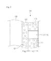
- FIG. 3 is a longitudinal cross-sectional view showing a soundproof member constituting the first exemplary embodiment of the present invention
- FIG. 4 is a plan view showing one surface of the soundproof member constituting the first exemplary embodiment of the present invention.
- a casing 10 forms an outer surface of an outdoor unit 1.
- An inlet (not shown) and an outlet 20 for flow-in and out of outdoor air are formed in the casing 10.
- various components constituting a heat-exchange cycle is installed in the casing 10.
- a blowing fan (not shown), an outdoor heat exchanger (not shown), a compressor 30 (see FIG. 2 ), and an accumulator 40 (see FIG. 2 ) are installed.
- the blowing fan forms the flow of air which flows in and out to the inside and the outside of the casing 10 through the inlet and the outlet 20.
- the outdoor heat exchanger operates as a condenser in a cooling operation and operates as an evaporator in a heating operation. Refrigerant that circulates throughout the heat exchange cycle exchanges heat with air that flow by driving the blowing fan while flowing in the outdoor heat exchanger.
- the compressor 30 serves to compress the refrigerant that circulates throughout the heat-exchange cycle.
- the accumulator 40 serves to separate liquid refrigerant to allow only gaseous refrigerant to flow into the compressor 30. Meanwhile, vibration and noise are generated by rotation of a motor while the compressor 30 compresses the refrigerant. In the exemplary embodiment, by using a soundproof member 100, the noise generated from the compressor 30 is prevented from being leaked to the outside of the casing 10, that is, the outside of the outdoor unit 1.
- the soundproof member 100 is installed to surround the compressor 30 and the accumulator 40.
- the soundproof member 100 contacts a part of an outer surface of each of the compressor 30 and the accumulator 40.
- the soundproof member 100 may substantially partition a region where the compressor 30 and the accumulator 30 are installed from an internal space of the outdoor unit 1.
- the soundproof member 100 is constituted by a plurality of members that absorb or insulate noise generated while the compressor 30 operates.
- the soundproof member 100 includes first and second sound absorption sections 110 and 120, and a sound insulation section 130.
- first sound absorption section 110 is provided in inner parts or the insides of the second sound absorption section 120 and the sound insulation section 130.
- each of the first and second absorption sections 110 and 120 and the sound insulation section 130 has a plate shape with a predetermined width and a predetermined thickness and a cross section thereof has substantially a circular shape or an elliptical shape.
- the second sound absorption section 120 is coupled along an outer peripheral surface of the first sound insulation section 110 and the sound insulation section 130 is coupled along an outer peripheral surface of the second sound absorption section 120.
- the soundproof member 100 surfaces of three members facing each other are fixed with contacting each other in the order of the first and second sound absorption sections 110 and 120 and the sound insulation section 130.
- the first and second sound absorption sections 110 and 120 and the sound insulation section 130 are placed to surround the compressor 30 and the accumulator in sequence.
- the second sound absorption section 120 is placed to surround the first sound absorption section 110 and the sound insulation section 130 is placed surround the second sound absorption section 120.
- one surface of the first sound absorption section 110 substantially forms an inner surface of the soundproof member 100 and one surface of the sound insulation section 130 forms an outer surface of the soundproof member 100.
- the sound insulation section 130 is furthest spaced apart from the compressor 30 and the accumulator 40 and the first sound absorption section 110 contacts at least a part of an outer surface of each of the compressor 30 and the accumulator 40.
- first and second sound absorption sections 110 and 120 serves to absorb the noise generated while the compressor 30 operates. More specifically, the first sound absorption section 110 absorbs noise in a relatively low-frequency range and the second sound absorption section 120 absorbs noise in a relatively high-frequency range.
- the high-frequency range and the low-frequency range may be divided based on for example, 1000 Hz.
- the first and second absorption sections 110 and 120 may be made of a material capable of absorbing the noise generated while the compressor 30 operates, i.e., a porous fiber material with a plurality of minute holes 111 and 121.
- the minute holes 111 and 121 are substantially in multiple numbers on the surfaces and in inner parts of the first and second sound absorption sections 110 and 120. That is, the minute holes 111 and 121 may not penetrate both surfaces of the first and second sound absorption sections 110 and 120.
- the first and second sound absorption sections 110 and 120 are not particularly made of the porous material with the plurality of minute holes 111 and 121. That is, the first and second sound absorption sections 110 and 120 may be molded as a material having predetermined sound absorption performance, not even the porous material.
- the thickness T1 of the first sound absorption section 110 is set to a value of 5 mm or more and the thickness T2 of the second sound absorption section 120 is set as a value smaller than the thickness T1 of the first sound absorption section 110.
- a plurality of holes 113 and 115 are formed in the first sound absorption section 110.
- the holes 113 and 115 penetrate the first sound absorption section 110 in a thickness direction. Therefore, both ends of the holes 113 and 115 are positioned at both ends of the first sound absorption section 110.
- the minute holes 111 and 121 are in multiple numbers on the surfaces and in inner parts of the first sound absorption section 110. Accordingly, the holes 113 and 115 may be configured different from the minute holes 111 and 121.
- the holes 113 and 115 include first and second holes 113 and 115.
- the diameter D1 of the first hole 113 is larger than the diameter D2 of the second hole 115.
- each of the diameters D1 and D2 of the first and second holes 113 and 115 may be set to a value to 10 mm or less.
- first and second holes 113 and 115 are spaced apart from each other as a lattice shape as a whole.
- each of the first and second holes 113 and 115 forms a column and the column of each of the first and second holes 113 and 115 are positioned to be alternated with each other.
- a distance L1 between the adjacent first holes 113, a distance L2 between the adjacent second holes 115, and a distance L3 between the first and second holes 113 and 115 are each set to values of 10 mm or more.
- the first sound absorption section 110 absorbs noise in a relatively lower-frequency range than the second sound absorption section 120.
- the frequency range of the noise absorbed by the first sound absorption section 110 is determined depending on the thickness T1 of the first sound absorption section 110, the diameters D1 and D2 of the holes 113 and 115, and the distances L1, L2, and L3 between the holes 113 and 115.
- noise in a frequency band around 1000 Hz e.g., a frequency band in the range of 200 to 800 Hz is relatively large. Therefore, when the thickness T of the first sound absorption section 110 is 5 mm or more, the diameters D of the holes 113 and 115 are 10 mm or less, and the distances L between the holes 113 and 115 are 10 mm or more, the noise in the frequency band is efficiently absorbed.
- the noise in the frequency band may be most efficiently absorbed (this will be described in more detail in a third exemplary embodiment of the present invention to be described below).
- the sound insulation member 130 serves to insulate the noise generated while the compressor 30 operates.
- the sound insulation member 130 is molded as a material capable of insulating noise, such as rubber, cork, glass fiber, or felt.
- the refrigerant compressed by the compressor 30 exchanges heat with indoor air and outdoor air while circulating throughout the heat exchange cycle to cool or heat a room.
- noise is generated while the refrigerant is compressed by the compressor 30.
- the noise generated from the compressor 30 is prevented from being leaked to the outside of the outdoor unit 1. That is, the noise generated from the compressor 30 is absorbed by the first and second sound absorption sections 110 and 120 and insulated by the sound insulation section 130 not to be leaked to the outside.
- the first sound absorption section 110 absorbs noise in a relatively low-frequency range
- the second sound absorption section 120 absorbs noise in a relatively high-frequency range.
- the noise in the relatively low-frequency band can be reduced as compared with the case in which the noise generated from the compressor 30 is prevented from being leaked by using a general sound absorption member or/and sound insulation member.
- the noise generated from the compressor 30 is larger in the low-frequency band than in the high-frequency band, the noise of the compressor 30 can be substantially prevented from being leaked more efficiently.
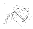
- FIG. 5 is a plan view of a principal part of an outdoor unit for an air conditioner according to a second exemplary embodiment of the present invention.
- a soundproof member 200 is provided in order to prevent noise generated while a compressor 30 operates from being leaked.
- the soundproof member 200 includes first and second soundproof members 210 and 220.
- the first soundproof member 210 is installed to surround the compressor 30 and an accumulator 40.
- the second soundproof member 220 surrounds the compressor 30 in the first soundproof member 210.
- the first soundproof member 210 includes a sound absorption section 211 and a sound insulation section 213.
- the configurations of the sound absorption section 211 and the sound insulation section 213 are the same as those of the second sound absorption section 12 and the sound insulation section 130 of the first exemplary embodiment, respectively.
- the configuration of the second soundproof member 220 is the same as that of the first sound absorption member 110. That is, the first and second holes are formed in the second soundproof member 220 and the minute holes may be formed in the sound absorption section 211 and the second soundproof member 220.
- the sound absorption section 211 forms an inner surface of the first soundproof member 210 and the sound insulation section 213 forms an outer surface of the first soundproof member 210.
- the inner surface of the first soundproof member 210 is placed to contact an outer peripheral surface of the accumulator 40.
- the second soundproof member 220 substantially serves to absorb the noise generated while the compressor 30 operates.
- the second soundproof member 220 is placed to surround the compressor.
- at least a part of an inner surface of the second soundproof member 220 contacts an outer surface of the compressor 30 and at least a part of an inner surface of the second soundproof member 220 may contact at least a part of the outer surface of the accumulator 40.
- the second soundproof member 220 surrounds the compressor 30, such that an internal space of the soundproof member 200 is partitioned into a first zone Z1 where the compressor 30 is positioned as an inner part of the second proof member 220 and an internal zone of the soundproof member 200 other than the first zone Z1, i.e., a second zone Z2 where the accumulator 40 is positioned.
- the noise generated while the compressor 30 operates in particular, noise in a relatively low-frequency band is absorbed.
- the first soundproof member 210 among the noises generated while the compressor 30 operates, noise in a relatively high-frequency band is absorbed and insulated.
- FIG. 6 is a plan view of a principal part of an outdoor unit for an air conditioner according to a third exemplary embodiment of the present invention
- FIG. 7 is a graph showing a difference in soundproof efficiency between the outdoor unit for the air conditioner according to the third exemplary embodiment of the present invention and the related art.
- first and second soundproof members 310 and 320 are provided in order to prevent noise generated while a compressor 30 operates from being leaked.
- the first soundproof member 310 is installed to surround the compressor 30 and an accumulator 40.
- the second soundproof member 320 is provided in the first soundproof member 310 to partition an internal space surrounded by the first soundproof member 310 into a first zone Z1 where the compressor 30 is positioned and a second zone Z2 where the accumulator 40 is positioned.
- first zone Z1 and the second zone Z2 may be defined as closed zones that are not in communication with each other.
- the first soundproof member 310 includes a sound absorption section 311 absorbing noise and a sound insulation section 313 insulating noise, and the second soundproof member 320 serves to absorb noise.
- a configuration of the first soundproof member 310 corresponds to the configuration of the first soundproof member 210 of the second exemplary embodiment and a configuration of the second soundproof member 320 corresponds to the configuration of the second soundproof member 220 of the second exemplary embodiment.
- the second soundproof member 320 has a plate shape and a space surrounded by the first soundproof member 310 is partitioned into the first and second zones Z1 and Z2.
- a distance between the first and second soundproof members 310 and 320 in a direction perpendicular to one surface of the second soundproof member 320 is determined as a value satisfying the following conditions.
- D1 represents a first longest distance which can be formed between one point of the first soundproof member 310 and one point of the second soundproof member 320 in the direction perpendicular to one surface of the second soundproof member 320 in the first zone Z1.
- D2 represents a second longest distance which can be formed between one point of the first soundproof member 310 and one point of the second soundproof member 320 in the direction perpendicular to one surface of the second soundproof member 320 in the second zone Z2.
- the conditions may be understood substantially as a value given by in order to increase absorption and insulation efficiency of, in particular, noise in a low-frequency band among the noises generated while the compressor 30 operates.
- D1 and D2 satisfy the conditions, leakage of the noise generated while the compressor 30 operates, in particular, the noise in the low-frequency band is remarkably reduced as compared with the related art. This will be more apparently understood with reference to FIG. 7 .
- an X-axis variable represents a frequency band of noise and a Y-axis variable represents the magnitude of noise.
- line (A) is noise of the compressor when only the first soundproof member is installed and line (B) is noise of the compressor when both the first and second soundproof members are installed, that is, in the exemplary embodiment.
- FIG. 8 is a plan view of a principal part of an outdoor unit for an air conditioner according to a fourth exemplary embodiment of the present invention.
- a first soundproof member and second soundproof members 421 and 423 are provided in order to prevent noise generated from being leaked while a compressor 30 operates.
- the first and second soundproof members 410, and 421 and 423 have the same components as the first and second soundproof members 310 and 320 of the third exemplary embodiment of the present invention, respectively.
- the second soundproof members 421 and 423 are configured in multiple numbers. That is, the second soundproof members 421 and 423 are constituted by two that cross each other.
- distances A1, A2, B1, and B2 among the first and second soundproof members 410, and 421 and 423 in a direction perpendicular to one surface of each of the second soundproof members 421 and 423 will be set to satisfy the same conditions as the third exemplary embodiment of the present invention.
- A1 and B1 satisfy the condition corresponding to D1 of the third exemplary embodiment and A2 and B2 satisfy the condition corresponding to D2 of the third exemplary embodiment.
- the holes formed in the first sound absorption section or the second soundproof member include the first and second holes having different diameters.
- the holes may have the same diameter or three different diameters.
- the second sound absorption section and the sound insulation section described in the first exemplary embodiment may be called the first soundproof member and the first sound absorption section may be called the second soundproof member.
- the second sound absorption section may be called the sound absorption section and the first sound absorption section may be called the second soundproof member.
Landscapes
- Engineering & Computer Science (AREA)
- Chemical & Material Sciences (AREA)
- Combustion & Propulsion (AREA)
- Mechanical Engineering (AREA)
- General Engineering & Computer Science (AREA)
- Compressor (AREA)
- Other Air-Conditioning Systems (AREA)
Applications Claiming Priority (1)
| Application Number | Priority Date | Filing Date | Title |
|---|---|---|---|
| KR1020100137599A KR101936192B1 (ko) | 2010-12-29 | 2010-12-29 | 공기조화기의 실외기 |
Publications (3)
| Publication Number | Publication Date |
|---|---|
| EP2472191A2 true EP2472191A2 (de) | 2012-07-04 |
| EP2472191A3 EP2472191A3 (de) | 2014-10-01 |
| EP2472191B1 EP2472191B1 (de) | 2017-12-06 |
Family
ID=44992572
Family Applications (1)
| Application Number | Title | Priority Date | Filing Date |
|---|---|---|---|
| EP11186606.7A Active EP2472191B1 (de) | 2010-12-29 | 2011-10-26 | Außenraumeinheit für Klimaanlage |
Country Status (4)
| Country | Link |
|---|---|
| US (1) | US8950208B2 (de) |
| EP (1) | EP2472191B1 (de) |
| KR (1) | KR101936192B1 (de) |
| CN (1) | CN102538083B (de) |
Cited By (1)
| Publication number | Priority date | Publication date | Assignee | Title |
|---|---|---|---|---|
| EP2977692A1 (de) * | 2014-07-23 | 2016-01-27 | Mitsubishi Heavy Industries, Ltd. | Kompressorsystem und klimaanlage damit |
Families Citing this family (21)
| Publication number | Priority date | Publication date | Assignee | Title |
|---|---|---|---|---|
| KR102355136B1 (ko) * | 2014-06-25 | 2022-01-26 | 엘지전자 주식회사 | 리니어 압축기, 리니어 압축기의 쉘, 리니어 압축기의 쉘 제작방법 |
| USD783790S1 (en) | 2014-09-26 | 2017-04-11 | Toshiba Carrier Corporation | Heat exchanger for an air conditioner |
| CN105485792B (zh) * | 2015-12-25 | 2019-04-19 | 广东美的制冷设备有限公司 | 压缩机组件、室外机及空调器 |
| CN105485794B (zh) * | 2015-12-25 | 2020-03-06 | 广东美的制冷设备有限公司 | 压缩机组件、室外机及空调器 |
| CN105444290B (zh) * | 2015-12-25 | 2019-06-04 | 广东美的制冷设备有限公司 | 压缩机组件、降噪箱、压缩机、室外机及空调器 |
| USD865139S1 (en) * | 2016-01-29 | 2019-10-29 | Mitsubishi Electric Corporation | Outdoor unit for water heater |
| CN107435637A (zh) * | 2017-08-28 | 2017-12-05 | 广东美的暖通设备有限公司 | 压缩机组件和具有它的空调器 |
| CN109695999A (zh) * | 2017-10-23 | 2019-04-30 | 青岛海尔股份有限公司 | 冷藏冷冻装置 |
| USD870161S1 (en) * | 2017-12-04 | 2019-12-17 | Everidge, Inc. | Blast chiller |
| JP2019100658A (ja) * | 2017-12-06 | 2019-06-24 | 株式会社富士通ゼネラル | 空気調和機の室外機 |
| JP2019120450A (ja) * | 2017-12-28 | 2019-07-22 | ダイキン工業株式会社 | 冷凍装置の熱源ユニット |
| CN108413516A (zh) * | 2018-04-23 | 2018-08-17 | 青岛海信日立空调系统有限公司 | 一种压缩机隔音罩、压缩机及空调室外机 |
| US20190376499A1 (en) * | 2018-06-07 | 2019-12-12 | Johnson Controls Technology Company | Relative vibration damping system for hvac systems |
| US20200132337A1 (en) * | 2018-10-31 | 2020-04-30 | Robert Scott KELLY | Covers for air conditioner units |
| JPWO2020178928A1 (ja) * | 2019-03-04 | 2021-09-30 | 三菱電機株式会社 | 室外機およびそれを備えた空気調和機 |
| EP3705793B1 (de) * | 2019-03-08 | 2021-05-19 | Daikin Industries, Ltd. | Wärmequelleneinheit für eine wärmepumpe |
| USD963000S1 (en) * | 2019-03-20 | 2022-09-06 | Thermo King Corporation | Refrigeration apparatus |
| CA200992S (en) * | 2020-05-06 | 2021-11-29 | Midea Group Co Ltd | Heater |
| JP1672192S (de) * | 2020-05-28 | 2020-11-09 | ||
| JP7507343B2 (ja) * | 2020-09-17 | 2024-06-28 | パナソニックIpマネジメント株式会社 | 空気調和機の室外ユニット |
| EP4553391A4 (de) * | 2022-09-28 | 2025-11-05 | Handan Midea Air Conditioning Equipment Co Ltd | Innenraumeinheit einer klimaanlage und geteilte klimaanlage |
Family Cites Families (26)
| Publication number | Priority date | Publication date | Assignee | Title |
|---|---|---|---|---|
| JPH0267823U (de) * | 1988-07-27 | 1990-05-23 | ||
| US4982812A (en) * | 1989-10-24 | 1991-01-08 | Hwang Min Su | Noise-preventive means for compressor used in air conditioner |
| JPH04171281A (ja) * | 1990-10-31 | 1992-06-18 | Sanyo Electric Co Ltd | 圧縮機の防音装置 |
| US5272285A (en) * | 1992-08-20 | 1993-12-21 | Scott Mfg., Inc. | Sound attenuating machinery cover |
| CN2132121Y (zh) * | 1992-10-16 | 1993-05-05 | 吴迪泉 | 低噪声房间空调器 |
| JPH0836389A (ja) * | 1994-07-21 | 1996-02-06 | Sharp Corp | 圧縮機の取付装置 |
| JPH08152229A (ja) * | 1994-11-25 | 1996-06-11 | Fujikura Ltd | 空気調和機 |
| US5588810A (en) * | 1995-09-01 | 1996-12-31 | Bristol Compressors, Inc. | Low noise refrigerant compressor |
| US5965851A (en) * | 1997-01-28 | 1999-10-12 | Owens Corning Fiberglas Technology, Inc. | Acoustically insulated apparatus |
| KR100288872B1 (en) * | 1998-01-20 | 2001-02-12 | Samsung Electronics Co Ltd | Noise reduction apparatus for air conditioner outdoor unit |
| JP3921795B2 (ja) * | 1998-03-31 | 2007-05-30 | 株式会社デンソー | 空調装置 |
| CN1183315C (zh) * | 1999-11-29 | 2005-01-05 | 株式会社必泰克 | 消声器 |
| JP2002243211A (ja) * | 2001-02-20 | 2002-08-28 | Fujitsu General Ltd | 空気調和機用圧縮機の吸音材 |
| KR100420520B1 (ko) * | 2001-10-05 | 2004-03-02 | 엘지전자 주식회사 | 대형 공기조화기의 실외기용 소음저감구조 |
| ITMI20020986A1 (it) * | 2002-05-10 | 2003-11-10 | Acraf | Composizione a base di diclofenac per il trattamento topico di affezioni del cavo orofaringeo |
| US6644061B1 (en) * | 2002-08-02 | 2003-11-11 | Joseph W. Woolfson | Sound muffling device for an air conditioning unit |
| JP2004143975A (ja) * | 2002-10-23 | 2004-05-20 | Hitachi Home & Life Solutions Inc | 圧縮機の防音装置 |
| JP2004183499A (ja) * | 2002-11-29 | 2004-07-02 | Denso Corp | 電動コンプレッサ |
| CA2475280A1 (en) * | 2003-07-21 | 2005-01-21 | Villa Olympic Inc. | Sound attenuating cover for domestic air conditioner compressors |
| CN2651645Y (zh) * | 2003-11-10 | 2004-10-27 | 珠海格力电器股份有限公司 | 隔音棉 |
| KR100598215B1 (ko) * | 2004-02-25 | 2006-07-07 | 엘지전자 주식회사 | 에어컨 실외기의 배관 구조 |
| CN2888126Y (zh) * | 2005-12-31 | 2007-04-11 | 郭自刚 | 改进式静音风泵 |
| JP4697477B2 (ja) * | 2007-06-29 | 2011-06-08 | 三菱電機株式会社 | ヒートポンプ給湯機 |
| JP2009014228A (ja) * | 2007-07-03 | 2009-01-22 | Daikin Ind Ltd | 冷凍装置 |
| CN201672646U (zh) * | 2010-04-02 | 2010-12-15 | 广州市延昌新型塑胶制品有限公司 | 空调压缩机低频隔音罩 |
| CN201672645U (zh) * | 2010-04-02 | 2010-12-15 | 广州市延昌新型塑胶制品有限公司 | 一种空调压缩机中频隔音罩 |
-
2010
- 2010-12-29 KR KR1020100137599A patent/KR101936192B1/ko active Active
-
2011
- 2011-10-26 EP EP11186606.7A patent/EP2472191B1/de active Active
- 2011-11-14 CN CN201110370303.9A patent/CN102538083B/zh not_active Expired - Fee Related
- 2011-11-29 US US13/306,404 patent/US8950208B2/en not_active Expired - Fee Related
Non-Patent Citations (1)
| Title |
|---|
| None |
Cited By (1)
| Publication number | Priority date | Publication date | Assignee | Title |
|---|---|---|---|---|
| EP2977692A1 (de) * | 2014-07-23 | 2016-01-27 | Mitsubishi Heavy Industries, Ltd. | Kompressorsystem und klimaanlage damit |
Also Published As
| Publication number | Publication date |
|---|---|
| CN102538083A (zh) | 2012-07-04 |
| CN102538083B (zh) | 2015-04-01 |
| US8950208B2 (en) | 2015-02-10 |
| EP2472191B1 (de) | 2017-12-06 |
| KR101936192B1 (ko) | 2019-01-08 |
| KR20120075770A (ko) | 2012-07-09 |
| EP2472191A3 (de) | 2014-10-01 |
| US20120167608A1 (en) | 2012-07-05 |
Similar Documents
| Publication | Publication Date | Title |
|---|---|---|
| US8950208B2 (en) | Outdoor unit for air conditioner | |
| KR100598215B1 (ko) | 에어컨 실외기의 배관 구조 | |
| US11148574B2 (en) | Refrigerator for vehicle and vehicle | |
| US20200248715A1 (en) | Soundproof cover of a compressor | |
| US10436459B2 (en) | Air guide for air conditioner | |
| KR102201761B1 (ko) | 실외기와 이를 포함하는 공기조화기 | |
| JP2009085528A (ja) | ヒートポンプ給湯機 | |
| CN202532792U (zh) | 毛细管的固定装置 | |
| JP2010151343A (ja) | 冷凍装置 | |
| KR20100078065A (ko) | 다중 소음 차단기 및 이를 포함하는 냉동공조제품 | |
| KR100758910B1 (ko) | 공기조화기의 실외기 | |
| KR102266827B1 (ko) | 공기 조화기 | |
| KR101873751B1 (ko) | 공기조화장치 | |
| US12422151B2 (en) | Sound and vibration damping enclosures for refrigerant compressors of climate control systems | |
| KR20150112626A (ko) | 공기 조화기의 실외기 | |
| JP2009186061A (ja) | 室外機及びこれを備えた空気調和装置 | |
| JP2012247186A (ja) | ヒートポンプ給湯機 | |
| WO2021064984A1 (ja) | 冷凍サイクル装置 | |
| KR100517609B1 (ko) | 공기조화기의 파이프용 방진부재 | |
| KR20010037825A (ko) | 소음저감 창문형 에어컨 | |
| CN219913271U (zh) | 空调室外机 | |
| KR100432694B1 (ko) | 에어컨 실외기의 소음 저감 구조 | |
| KR20040044683A (ko) | 공기조화기의 실외기 소음저감구조 | |
| KR101565426B1 (ko) | 다중 소음 차단기 및 이를 포함하는 냉동공조제품 | |
| JP2009036248A (ja) | 真空断熱材及び真空断熱材を備えた圧縮機 |
Legal Events
| Date | Code | Title | Description |
|---|---|---|---|
| 17P | Request for examination filed |
Effective date: 20111123 |
|
| AK | Designated contracting states |
Kind code of ref document: A2 Designated state(s): AL AT BE BG CH CY CZ DE DK EE ES FI FR GB GR HR HU IE IS IT LI LT LU LV MC MK MT NL NO PL PT RO RS SE SI SK SM TR |
|
| AX | Request for extension of the european patent |
Extension state: BA ME |
|
| PUAI | Public reference made under article 153(3) epc to a published international application that has entered the european phase |
Free format text: ORIGINAL CODE: 0009012 |
|
| PUAL | Search report despatched |
Free format text: ORIGINAL CODE: 0009013 |
|
| AK | Designated contracting states |
Kind code of ref document: A3 Designated state(s): AL AT BE BG CH CY CZ DE DK EE ES FI FR GB GR HR HU IE IS IT LI LT LU LV MC MK MT NL NO PL PT RO RS SE SI SK SM TR |
|
| AX | Request for extension of the european patent |
Extension state: BA ME |
|
| RIC1 | Information provided on ipc code assigned before grant |
Ipc: F24F 13/24 20060101ALI20140826BHEP Ipc: F24F 1/08 20110101ALI20140826BHEP Ipc: F24F 13/20 20060101ALI20140826BHEP Ipc: F24F 1/00 20110101AFI20140826BHEP Ipc: F24F 1/12 20110101ALI20140826BHEP |
|
| RBV | Designated contracting states (corrected) |
Designated state(s): AL AT BE BG CH CY CZ DE DK EE ES FI FR GB GR HR HU IE IS IT LI LT LU LV MC MK MT NL NO PL PT RO RS SE SI SK SM TR |
|
| GRAP | Despatch of communication of intention to grant a patent |
Free format text: ORIGINAL CODE: EPIDOSNIGR1 |
|
| STAA | Information on the status of an ep patent application or granted ep patent |
Free format text: STATUS: GRANT OF PATENT IS INTENDED |
|
| RIC1 | Information provided on ipc code assigned before grant |
Ipc: F24F 1/12 20110101ALI20170502BHEP Ipc: F24F 13/20 20060101ALI20170502BHEP Ipc: F24F 1/00 20110101AFI20170502BHEP Ipc: F24F 13/24 20060101ALI20170502BHEP Ipc: F24F 1/08 20110101ALI20170502BHEP |
|
| INTG | Intention to grant announced |
Effective date: 20170529 |
|
| GRAS | Grant fee paid |
Free format text: ORIGINAL CODE: EPIDOSNIGR3 |
|
| GRAA | (expected) grant |
Free format text: ORIGINAL CODE: 0009210 |
|
| STAA | Information on the status of an ep patent application or granted ep patent |
Free format text: STATUS: THE PATENT HAS BEEN GRANTED |
|
| AK | Designated contracting states |
Kind code of ref document: B1 Designated state(s): AL AT BE BG CH CY CZ DE DK EE ES FI FR GB GR HR HU IE IS IT LI LT LU LV MC MK MT NL NO PL PT RO RS SE SI SK SM TR |
|
| REG | Reference to a national code |
Ref country code: GB Ref legal event code: FG4D |
|
| REG | Reference to a national code |
Ref country code: AT Ref legal event code: REF Ref document number: 952738 Country of ref document: AT Kind code of ref document: T Effective date: 20171215 Ref country code: CH Ref legal event code: EP |
|
| REG | Reference to a national code |
Ref country code: IE Ref legal event code: FG4D |
|
| REG | Reference to a national code |
Ref country code: DE Ref legal event code: R096 Ref document number: 602011043919 Country of ref document: DE |
|
| REG | Reference to a national code |
Ref country code: NL Ref legal event code: MP Effective date: 20171206 |
|
| REG | Reference to a national code |
Ref country code: LT Ref legal event code: MG4D |
|
| PG25 | Lapsed in a contracting state [announced via postgrant information from national office to epo] |
Ref country code: NO Free format text: LAPSE BECAUSE OF FAILURE TO SUBMIT A TRANSLATION OF THE DESCRIPTION OR TO PAY THE FEE WITHIN THE PRESCRIBED TIME-LIMIT Effective date: 20180306 Ref country code: SE Free format text: LAPSE BECAUSE OF FAILURE TO SUBMIT A TRANSLATION OF THE DESCRIPTION OR TO PAY THE FEE WITHIN THE PRESCRIBED TIME-LIMIT Effective date: 20171206 Ref country code: ES Free format text: LAPSE BECAUSE OF FAILURE TO SUBMIT A TRANSLATION OF THE DESCRIPTION OR TO PAY THE FEE WITHIN THE PRESCRIBED TIME-LIMIT Effective date: 20171206 Ref country code: LT Free format text: LAPSE BECAUSE OF FAILURE TO SUBMIT A TRANSLATION OF THE DESCRIPTION OR TO PAY THE FEE WITHIN THE PRESCRIBED TIME-LIMIT Effective date: 20171206 Ref country code: FI Free format text: LAPSE BECAUSE OF FAILURE TO SUBMIT A TRANSLATION OF THE DESCRIPTION OR TO PAY THE FEE WITHIN THE PRESCRIBED TIME-LIMIT Effective date: 20171206 |
|
| REG | Reference to a national code |
Ref country code: AT Ref legal event code: MK05 Ref document number: 952738 Country of ref document: AT Kind code of ref document: T Effective date: 20171206 |
|
| PG25 | Lapsed in a contracting state [announced via postgrant information from national office to epo] |
Ref country code: BG Free format text: LAPSE BECAUSE OF FAILURE TO SUBMIT A TRANSLATION OF THE DESCRIPTION OR TO PAY THE FEE WITHIN THE PRESCRIBED TIME-LIMIT Effective date: 20180306 Ref country code: RS Free format text: LAPSE BECAUSE OF FAILURE TO SUBMIT A TRANSLATION OF THE DESCRIPTION OR TO PAY THE FEE WITHIN THE PRESCRIBED TIME-LIMIT Effective date: 20171206 Ref country code: LV Free format text: LAPSE BECAUSE OF FAILURE TO SUBMIT A TRANSLATION OF THE DESCRIPTION OR TO PAY THE FEE WITHIN THE PRESCRIBED TIME-LIMIT Effective date: 20171206 Ref country code: HR Free format text: LAPSE BECAUSE OF FAILURE TO SUBMIT A TRANSLATION OF THE DESCRIPTION OR TO PAY THE FEE WITHIN THE PRESCRIBED TIME-LIMIT Effective date: 20171206 Ref country code: GR Free format text: LAPSE BECAUSE OF FAILURE TO SUBMIT A TRANSLATION OF THE DESCRIPTION OR TO PAY THE FEE WITHIN THE PRESCRIBED TIME-LIMIT Effective date: 20180307 |
|
| PG25 | Lapsed in a contracting state [announced via postgrant information from national office to epo] |
Ref country code: NL Free format text: LAPSE BECAUSE OF FAILURE TO SUBMIT A TRANSLATION OF THE DESCRIPTION OR TO PAY THE FEE WITHIN THE PRESCRIBED TIME-LIMIT Effective date: 20171206 |
|
| PG25 | Lapsed in a contracting state [announced via postgrant information from national office to epo] |
Ref country code: CZ Free format text: LAPSE BECAUSE OF FAILURE TO SUBMIT A TRANSLATION OF THE DESCRIPTION OR TO PAY THE FEE WITHIN THE PRESCRIBED TIME-LIMIT Effective date: 20171206 Ref country code: SK Free format text: LAPSE BECAUSE OF FAILURE TO SUBMIT A TRANSLATION OF THE DESCRIPTION OR TO PAY THE FEE WITHIN THE PRESCRIBED TIME-LIMIT Effective date: 20171206 Ref country code: EE Free format text: LAPSE BECAUSE OF FAILURE TO SUBMIT A TRANSLATION OF THE DESCRIPTION OR TO PAY THE FEE WITHIN THE PRESCRIBED TIME-LIMIT Effective date: 20171206 |
|
| PG25 | Lapsed in a contracting state [announced via postgrant information from national office to epo] |
Ref country code: RO Free format text: LAPSE BECAUSE OF FAILURE TO SUBMIT A TRANSLATION OF THE DESCRIPTION OR TO PAY THE FEE WITHIN THE PRESCRIBED TIME-LIMIT Effective date: 20171206 Ref country code: IT Free format text: LAPSE BECAUSE OF FAILURE TO SUBMIT A TRANSLATION OF THE DESCRIPTION OR TO PAY THE FEE WITHIN THE PRESCRIBED TIME-LIMIT Effective date: 20171206 Ref country code: SM Free format text: LAPSE BECAUSE OF FAILURE TO SUBMIT A TRANSLATION OF THE DESCRIPTION OR TO PAY THE FEE WITHIN THE PRESCRIBED TIME-LIMIT Effective date: 20171206 Ref country code: AT Free format text: LAPSE BECAUSE OF FAILURE TO SUBMIT A TRANSLATION OF THE DESCRIPTION OR TO PAY THE FEE WITHIN THE PRESCRIBED TIME-LIMIT Effective date: 20171206 Ref country code: PL Free format text: LAPSE BECAUSE OF FAILURE TO SUBMIT A TRANSLATION OF THE DESCRIPTION OR TO PAY THE FEE WITHIN THE PRESCRIBED TIME-LIMIT Effective date: 20171206 |
|
| REG | Reference to a national code |
Ref country code: DE Ref legal event code: R097 Ref document number: 602011043919 Country of ref document: DE |
|
| PLBE | No opposition filed within time limit |
Free format text: ORIGINAL CODE: 0009261 |
|
| STAA | Information on the status of an ep patent application or granted ep patent |
Free format text: STATUS: NO OPPOSITION FILED WITHIN TIME LIMIT |
|
| 26N | No opposition filed |
Effective date: 20180907 |
|
| PG25 | Lapsed in a contracting state [announced via postgrant information from national office to epo] |
Ref country code: DK Free format text: LAPSE BECAUSE OF FAILURE TO SUBMIT A TRANSLATION OF THE DESCRIPTION OR TO PAY THE FEE WITHIN THE PRESCRIBED TIME-LIMIT Effective date: 20171206 Ref country code: SI Free format text: LAPSE BECAUSE OF FAILURE TO SUBMIT A TRANSLATION OF THE DESCRIPTION OR TO PAY THE FEE WITHIN THE PRESCRIBED TIME-LIMIT Effective date: 20171206 |
|
| REG | Reference to a national code |
Ref country code: CH Ref legal event code: PL |
|
| GBPC | Gb: european patent ceased through non-payment of renewal fee |
Effective date: 20181026 |
|
| REG | Reference to a national code |
Ref country code: BE Ref legal event code: MM Effective date: 20181031 |
|
| PG25 | Lapsed in a contracting state [announced via postgrant information from national office to epo] |
Ref country code: MC Free format text: LAPSE BECAUSE OF FAILURE TO SUBMIT A TRANSLATION OF THE DESCRIPTION OR TO PAY THE FEE WITHIN THE PRESCRIBED TIME-LIMIT Effective date: 20171206 Ref country code: LU Free format text: LAPSE BECAUSE OF NON-PAYMENT OF DUE FEES Effective date: 20181026 |
|
| REG | Reference to a national code |
Ref country code: IE Ref legal event code: MM4A |
|
| PG25 | Lapsed in a contracting state [announced via postgrant information from national office to epo] |
Ref country code: FR Free format text: LAPSE BECAUSE OF NON-PAYMENT OF DUE FEES Effective date: 20181031 Ref country code: CH Free format text: LAPSE BECAUSE OF NON-PAYMENT OF DUE FEES Effective date: 20181031 Ref country code: LI Free format text: LAPSE BECAUSE OF NON-PAYMENT OF DUE FEES Effective date: 20181031 Ref country code: BE Free format text: LAPSE BECAUSE OF NON-PAYMENT OF DUE FEES Effective date: 20181031 |
|
| PG25 | Lapsed in a contracting state [announced via postgrant information from national office to epo] |
Ref country code: IE Free format text: LAPSE BECAUSE OF NON-PAYMENT OF DUE FEES Effective date: 20181026 Ref country code: GB Free format text: LAPSE BECAUSE OF NON-PAYMENT OF DUE FEES Effective date: 20181026 |
|
| PG25 | Lapsed in a contracting state [announced via postgrant information from national office to epo] |
Ref country code: MT Free format text: LAPSE BECAUSE OF NON-PAYMENT OF DUE FEES Effective date: 20181026 |
|
| PG25 | Lapsed in a contracting state [announced via postgrant information from national office to epo] |
Ref country code: TR Free format text: LAPSE BECAUSE OF FAILURE TO SUBMIT A TRANSLATION OF THE DESCRIPTION OR TO PAY THE FEE WITHIN THE PRESCRIBED TIME-LIMIT Effective date: 20171206 |
|
| PG25 | Lapsed in a contracting state [announced via postgrant information from national office to epo] |
Ref country code: PT Free format text: LAPSE BECAUSE OF FAILURE TO SUBMIT A TRANSLATION OF THE DESCRIPTION OR TO PAY THE FEE WITHIN THE PRESCRIBED TIME-LIMIT Effective date: 20171206 |
|
| PG25 | Lapsed in a contracting state [announced via postgrant information from national office to epo] |
Ref country code: MK Free format text: LAPSE BECAUSE OF NON-PAYMENT OF DUE FEES Effective date: 20171206 Ref country code: HU Free format text: LAPSE BECAUSE OF FAILURE TO SUBMIT A TRANSLATION OF THE DESCRIPTION OR TO PAY THE FEE WITHIN THE PRESCRIBED TIME-LIMIT; INVALID AB INITIO Effective date: 20111026 Ref country code: CY Free format text: LAPSE BECAUSE OF FAILURE TO SUBMIT A TRANSLATION OF THE DESCRIPTION OR TO PAY THE FEE WITHIN THE PRESCRIBED TIME-LIMIT Effective date: 20171206 |
|
| PG25 | Lapsed in a contracting state [announced via postgrant information from national office to epo] |
Ref country code: AL Free format text: LAPSE BECAUSE OF FAILURE TO SUBMIT A TRANSLATION OF THE DESCRIPTION OR TO PAY THE FEE WITHIN THE PRESCRIBED TIME-LIMIT Effective date: 20171206 Ref country code: IS Free format text: LAPSE BECAUSE OF FAILURE TO SUBMIT A TRANSLATION OF THE DESCRIPTION OR TO PAY THE FEE WITHIN THE PRESCRIBED TIME-LIMIT Effective date: 20180406 |
|
| PGFP | Annual fee paid to national office [announced via postgrant information from national office to epo] |
Ref country code: DE Payment date: 20240905 Year of fee payment: 14 |