EP2472211A2 - Dispositif de répartition et dispositif d'échangeur de chaleur - Google Patents
Dispositif de répartition et dispositif d'échangeur de chaleur Download PDFInfo
- Publication number
- EP2472211A2 EP2472211A2 EP20110009614 EP11009614A EP2472211A2 EP 2472211 A2 EP2472211 A2 EP 2472211A2 EP 20110009614 EP20110009614 EP 20110009614 EP 11009614 A EP11009614 A EP 11009614A EP 2472211 A2 EP2472211 A2 EP 2472211A2
- Authority
- EP
- European Patent Office
- Prior art keywords
- fluid
- heat exchanger
- distribution
- container
- distributor
- Prior art date
- Legal status (The legal status is an assumption and is not a legal conclusion. Google has not performed a legal analysis and makes no representation as to the accuracy of the status listed.)
- Granted
Links
Images

Classifications
-
- F—MECHANICAL ENGINEERING; LIGHTING; HEATING; WEAPONS; BLASTING
- F28—HEAT EXCHANGE IN GENERAL
- F28F—DETAILS OF HEAT-EXCHANGE AND HEAT-TRANSFER APPARATUS, OF GENERAL APPLICATION
- F28F9/00—Casings; Header boxes; Auxiliary supports for elements; Auxiliary members within casings
- F28F9/02—Header boxes; End plates
- F28F9/026—Header boxes; End plates with static flow control means, e.g. with means for uniformly distributing heat exchange media into conduits
-
- F—MECHANICAL ENGINEERING; LIGHTING; HEATING; WEAPONS; BLASTING
- F28—HEAT EXCHANGE IN GENERAL
- F28D—HEAT-EXCHANGE APPARATUS, NOT PROVIDED FOR IN ANOTHER SUBCLASS, IN WHICH THE HEAT-EXCHANGE MEDIA DO NOT COME INTO DIRECT CONTACT
- F28D3/00—Heat-exchange apparatus having stationary conduit assemblies for one heat-exchange medium only, the media being in contact with different sides of the conduit wall, in which the other heat-exchange medium flows in a continuous film, or trickles freely, over the conduits
- F28D3/04—Distributing arrangements
-
- F—MECHANICAL ENGINEERING; LIGHTING; HEATING; WEAPONS; BLASTING
- F28—HEAT EXCHANGE IN GENERAL
- F28F—DETAILS OF HEAT-EXCHANGE AND HEAT-TRANSFER APPARATUS, OF GENERAL APPLICATION
- F28F9/00—Casings; Header boxes; Auxiliary supports for elements; Auxiliary members within casings
- F28F9/02—Header boxes; End plates
- F28F9/026—Header boxes; End plates with static flow control means, e.g. with means for uniformly distributing heat exchange media into conduits
- F28F9/0265—Header boxes; End plates with static flow control means, e.g. with means for uniformly distributing heat exchange media into conduits by using guiding means or impingement means inside the header box
-
- Y—GENERAL TAGGING OF NEW TECHNOLOGICAL DEVELOPMENTS; GENERAL TAGGING OF CROSS-SECTIONAL TECHNOLOGIES SPANNING OVER SEVERAL SECTIONS OF THE IPC; TECHNICAL SUBJECTS COVERED BY FORMER USPC CROSS-REFERENCE ART COLLECTIONS [XRACs] AND DIGESTS
- Y10—TECHNICAL SUBJECTS COVERED BY FORMER USPC
- Y10T—TECHNICAL SUBJECTS COVERED BY FORMER US CLASSIFICATION
- Y10T137/00—Fluid handling
- Y10T137/8593—Systems
Definitions
- the present invention relates to a distribution device for distributing a fluid, which in particular has a liquid fraction and a gas fraction. Furthermore, the invention relates to a heat exchanger device with a corresponding distributor.
- Distribution devices are known, for example, as inlet distributors when two or more phase fluids are introduced into a container.
- vane inlet devices are known in order to achieve an even distribution and improved pre-separation of the fluid.
- the DE 10 2009 022 673 A1 discloses, for example, arranged on a floor panel vanes in the manner of slats with lugs as a distributor.
- the DE 39 13 579 A1 discloses, for example, a heat exchanger with a jacket space through continuous tubes in which the medium to be cooled flows.
- a baffle plate is proposed. The disclosed baffle is provided with holes and arranged in a horizontal plane in the flow space.
- a distributor for distributing a fluid in a container from a fluid inlet of the container.
- the distributor device has at least one guide plate with a guide section and a distributor section adjoining the guide section.
- the distribution section has areas with openings for the passage of the fluid.
- the distribution device can be laterally closed in such a fluid-tight manner that fluid can only pass downwards through the openings and is otherwise held by the distribution device.
- the fluid may in particular have a liquid fraction and a gas fraction.
- the fluid may be a refrigerant which enters a jacket space as a container as gas-liquid mixture.
- a corresponding fluid flows only locally in the region of a fluid inlet or inlet nozzle of the container, a particularly favorable homogeneous fluid distribution is achieved by the distributor, which can also be referred to as inlet flow diverter.
- the distribution device is particularly suitable for use in a cryogenic plant. Areas of application, however, include other process engineering systems in which heat exchangers are used. This may be the case, for example, in the context of gas liquefaction or air separation.
- the guide plate is designed as a bent sheet with a profile.
- the profile may be, for example, a circular section, a bent angle or an edge profile, for example in the manner of an L-angle.
- the guide section and the distributor section are formed by at least two guide plates arranged one against the other and substantially perpendicular to one another.
- the guide plates may for example have a rectangular shape.
- the distribution plate has openings, such as holes, gaps, slits, or, for example, material removal machined recesses with different geometries, in particular to pass fluid downwardly.
- the distribution device is arranged horizontally.
- the distribution section forms, for example, a horizontal area with holes or slot openings.
- an embodiment of the distribution device for distributing a fluid in a container from a fluid inlet of the container comprises at least two guide plates arranged one against the other and substantially perpendicular to one another.
- one of the guide plates on areas with openings for the passage of the fluid.
- the first guide plate may in particular be designed as a baffle plate and the second guide plate as a distribution plate.
- the designed as baffle guide plate preferably extends vertically and running as a distribution plate baffle horizontal.
- the distributor is laterally vertically completely or partially closed, so that a fluid flow is passed through the openings of the Verteilblechs substantially.
- the two guide plates form an L-profile, and on end faces of the L-profile side plates are arranged.
- the Side plates for example, close off the distributor laterally fluid-tight.
- the openings are designed as slots.
- the slots are formed in particular in the distribution plate and in the direction substantially perpendicular to an edge of the distributor plate or a profile angle.
- the distributor is preferably formed at least partially of aluminum or stainless steel.
- the choice of material can be adapted to the particular use of the distribution device, for example in cryogenic plants.
- thermoelectric device with a container which has a fluid inlet, at least one heat exchanger block arranged in the container, and with a distributor arranged in the container above the heat exchanger block.
- the heat exchanger device is designed in particular as a block-in-container heat exchanger. This is also referred to as core-in-shell or block-in-kettle heat exchanger arrangements.
- several, usually designed as a plate heat exchanger heat exchanger blocks are arranged in a container or in a jacket space next to each other in the rule.
- the shell space forms, for example, a flow space for the cooling medium, which is usually evaporated isothermally, wherein the fluid flowing in the heat exchanger block is cooled.
- the heat exchanger blocks are preferably arranged at the same level. There may also be a non-isothermal evaporation.
- an embodiment of the heat exchanger device to a container with a fluid inlet, a plurality of arranged in the container Heat exchanger blocks and above the heat exchanger blocks, a distributor for distributing the fluid flowing through the fluid inlet, wherein the distributor comprises at least one guide plate having a guide portion and a distributor portion adjacent to the guide portion, and wherein the distribution portion having portions with openings for passage of the fluid.
- the container is cylindrical and forms a jacket space for a flow area for the refrigerant.
- the cylinder axis is preferably arranged horizontally.
- the distribution device is formed of a baffle plate, which is vertical, and a distribution plate which extends horizontally along or parallel to the cylinder axis.
- the downwardly directed openings in the distribution plate are above the heat exchanger blocks or the block. Above is understood to be higher than in a vertical direction.
- the distributor does not necessarily have to run completely over the heat exchanger blocks.
- the distributor device is arranged in the container in such a way that a fluid flowing into the container through the fluid inlet flows through the openings of the distributor section into predetermined jacket regions in a targeted manner.
- inflowing fluid at least partially falls on the heat exchanger block.
- the arrangement and design of the openings allows a targeted distribution of the liquid portion of the fluid through the openings on or adjacent to or the heat exchanger blocks in the shell space.
- the distributor fluid in particular liquid, is introduced or distributed in areas of the shell space, where possible little or no gas is generated by evaporation, for example by a heat exchanger block.
- the distributor fluid in particular liquid
- the distributor fluid is introduced or distributed in areas of the shell space, where possible little or no gas is generated by evaporation, for example by a heat exchanger block.
- the separation of a gas and liquid phase is thereby improved.
- the distribution device together with walls of the container and the optional side plates, delimits a space portion in the container.
- the distributor and walls of the container include a space portion.
- the space portion for example in the manner of a distribution channel, connects the fluid inlet in a wall of the container with the flow space by means of the openings in the distribution section of the distributor.
- the space portion is coupled upstream of the fluid inlet and outflow coupled to the openings as an outlet.
- the fluid inlet has an inlet cross-sectional area and an inlet direction.
- the distribution device preferably has a longitudinal axis, which is designed to be horizontal and parallel along the longitudinal extent of the container.
- the longitudinal extent of the distributor is perpendicular to the direction of entry.
- the openings are designed as slots perpendicular to a longitudinal axis of the container.
- the slots extend, for example, parallel to cross-sectional areas of the space portion or of the container, which are formed perpendicular to a longitudinal axis of the container.
- the cross section of a distribution channel formed by means of the distributor and walls of the container corresponds to an inlet cross section of the fluid inlet. This can be a particularly favorable Realize flow distribution, for example, from the fluid inlet to the left and right of a corresponding nozzle away.
- the distribution device is designed in the manner of an L-profile sheet.
- the slot width is between 30 mm and 70 mm. Most preferably, the slots are 50mm wide.
- the openings are made as slots, and the slots are spaced from an edge or angle of the L profile sheet between 40 mm and 100 mm. Particularly preferably, the distance between 60 mm and 80 mm.
- a total cross-sectional area of all openings is between 150% and 250% of the cross-sectional area of the fluid inlet. Particularly preferably, the total cross-sectional area of the openings is twice as large as the cross-sectional area of the inlet.
- the distributor is then preferably completed by side plates. In principle, several inlet ports are conceivable.
- the distribution section of the distribution device is configured with fluid-tight regions such that no heat exchanger block is below the fluid-tight region.
- the distribution section of the distribution device is provided with openings exclusively directly above the heat exchanger block (s) and is otherwise made fluid-tight. As a result, no fluid drips or flows into areas between adjacent heat exchanger blocks in the container.
- the heat exchanger blocks and the distribution device are arranged such that openings of the distribution section are present above the heat exchanger blocks and the distribution section is otherwise closed.
- the distribution section of the distribution device is provided with openings next to or between the heat exchanger blocks and otherwise configured fluid-tight. As a result, no fluid drips or flows into areas above the heat exchanger blocks in the container.
- the heat exchanger blocks and the distribution device are arranged such that openings of the distribution section are present alongside or laterally of the heat exchanger blocks and the distribution section is otherwise closed.
- one or more fluid outlets are provided in addition to a fluid inlet. Below the fluid outlet nozzle of the container, in particular for gaseous fluid, no openings of the distribution section of the distributor are provided.
- the fluid is distributed as a cooling medium from above via a horizontal distribution channel by means of the distributor to where there is a favorable flow around the heat exchanger blocks.
- the arrangement of the openings, the fluid can be selectively directed into areas of the flow area with the heat exchanger blocks, in which a gas-liquid separation is efficiently possible.
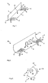
- the FIG. 1 shows a perspective schematic representation of a first embodiment of a distribution device.
- the distributor 1 comprises a vertical and a horizontal baffle which form an L-angle along a common edge 13.
- the vertical guide plate 2 serves as a guide section and the horizontal distribution plate 3 as a distribution section.
- the distribution plate 3 has areas 4, 5 with openings 8, 9. Between the areas 4, 5 with the openings 8, 9, a fluid-tight region 10 is provided. Through the openings, which in the FIG. 1 in the rear region 4 are designed as slots 8, and in the front region 5 are formed as holes 9, fluid can pass downwards.
- the distribution device 1 as in the FIG. 1 is shown, combines the functions of a perforated baffle plate with that of an inlet flow diverter, so a manifold near a flow nozzle of a container.
- the guide section 2 essentially serves to drain fluid or divert it.
- the distribution section 3 makes it possible, with the aid of the openings 8, 9, to dispense fluid specifically below the distribution device 1.
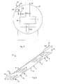
- the FIG. 2 shows a perspective schematic representation of a second embodiment of a distribution device.
- the distribution device 18 is designed in the manner of a curved guide plate.
- the FIG. 2 shows one in the orientation of the FIG. 2 vertical guide section 2 and a horizontal distribution section 3 of the baffle.
- In the distribution section 3 are provided areas 4, 5 with longitudinal openings 8 in the manner of slits.
- In the central region 10 of the distribution section 3 are no holes or slits.
- FIG. 2 is a possible fluid flow indicated by arrows.
- inflowing through an inlet connection of a container fluid 15 reaches the baffle of the distribution device 18.
- the fluid is pressed substantially horizontally to the left and right, as indicated by the arrows 16.
- the fluid flows or flows along the fluid-tight region 10 in the direction of the areas 4, 5 provided with openings 8.
- the fluid exits through the openings 8 downwards, which is indicated by arrows 17.
- FIG. 3 shows a schematic cross-sectional view of a third embodiment of a distribution device.
- the in the FIG. 3 distributor device 24 shown is manufactured as a circular segment-shaped profile, for example from a sheet metal such as aluminum or stainless steel.
- a distribution section 2 is provided opposite a container opening or a fluid inlet 26. Fluid 15 flowing in through the fluid inlet 26 strikes the distributor section 2 of the distributor device 24. In the lower region, downwardly directed openings are provided in the plate of the distributor device 24, which are shown dotted. The circular section, which points essentially downwards, is referred to as the distribution section 3. Due to the plate areas provided with openings in the areas 4, the fluid 17 can escape downwards.
- the arrangement and positioning of the openings within the distribution channel 23 can be a targeted supply of fluid, for example, in the direction of heat exchanger blocks.
- gravitational acceleration which is usually shown vertically. Horizontal in this context means perpendicular to the gravitational acceleration.
- FIG. 4 a heat exchanger device 100 shown in longitudinal section.
- FIG. 5 FIG. 3 illustrates a section AA transverse to an axis of symmetry of the heat exchanger device 100.
- FIG. 6 an illustration of a fourth embodiment of a distributor 101 is shown in perspective, which is provided in the heat exchanger device 100.
- the heat exchanger device 100 is configured as a block-in-tank configuration. That is, a plurality of heat exchanger blocks 28, 29, 30 are installed within a cylindrical container 27, which is also referred to as a jacket.
- a block-in-container arrangement which is also referred to as core-in-shell or block-in-kettle, is in particular that heat exchanger blocks in the form of plate heat exchangers can be used particularly efficiently.
- plate heat exchangers several layers of heat exchange passages are delimited by separating plates against each other, which usually leads to a cuboid block.
- FIG. 4 detects, in a cylindrical container 27 whose longitudinal axis 34, which is also an axis of symmetry and extends horizontally, three heat exchanger blocks 28, 29, 30 are provided.
- fluid to be liquefied such as natural gas or a process gas
- inlet ports 31 which pierce the jacket or tank 27 in an upper region
- outlet nozzle 32 which are provided in the lower region of the shell 27, is discharged.
- a mainly liquid refrigerant is usually isothermal evaporated.
- a fluid inlet 26 is provided approximately in the middle in the upper region in the jacket 27.
- the fluid is referred to below as a refrigerant or cryogen.
- the refrigerant occurs locally as a gas-liquid mixture.
- the liquid fraction is vaporized at the heat exchanger blocks 28, 29, 30 and exits as gas through fluid outlet openings 33 from the jacket space again.
- the fluid inlet 26 is arranged lower than the fluid outlets 33 for the cold medium. It is desirable that only the gas portion of the refrigerant from the shell space via the outlet nozzle or fluid outlets 23 is withdrawn. In order to reduce entrainment of liquid refrigerant as much as possible, an improved distribution of the entering through the fluid inlet nozzle 26 gas-liquid mixture is desired. Therefore, a distributor 101 is provided in the container 27.
- FIG. 5 In particular in the cross-sectional representation of FIG. 5 can be seen the circular cross-section of the cylinder jacket 27 as a container and provided in the interior heat exchanger block 28 with an inlet 31 and a drain 32 for fluid to be cooled. In the orientation of FIG. 5 is provided in the upper left circular segment of the fluid inlet 26.
- the refrigerant 15 enters a distribution channel 23 there.
- the distribution channel 23 is formed by a space portion within the shell 27, which is formed by the jacket wall 25 and an L-shaped guide plate of a guide portion and a distribution section 3.
- FIG. 6 shows a perspective view of an embodiment of the distributor 101.
- the FIG. 6 shows the distributor 101 with a baffle 2, which is provided vertically and a distribution plate 3, which is provided horizontally.
- side plates 19, 20 are provided, which are placed on the L-profile edges and connected fluid-tight and are connected to the guide and distribution plates 2, 3.
- An edge or contour 21, 22 of Side plates 19, 20 nestles against the container wall 25 (see. FIG. 5 ) and forms a fluid-tight seal with the container wall or jacket wall 25.
- the resulting space section or distribution channel 23 thus connects the fluid inlet 26 with the interior of the shell 27 via the openings 8 in the distribution plate 3.
- the openings 8 are slit-shaped and extend substantially perpendicular to a longitudinal extension of the distributor 101 and perpendicular to an axis of symmetry 34 of the container 27th
- FIGS. 4 . 5 and 6 One recognizes in conjunction with the FIGS. 4 . 5 and 6 in that fluid-tight regions 10, 11, 12 are provided in the distribution plate 3, where, on the one hand, there is no heat exchanger block 28, 29, 30 below the distribution plate 3 and, on the other hand, inlet or outlet ports 26, 33 are arranged above the distribution plate 3.
- the areas 4, 5, 6, 7 with openings 8 are provided substantially exclusively above but between the heat exchanger blocks 28, 29, 30. This ensures that a gas-liquid separation of the refrigerant medium takes place uniformly over the entire container length and liquid refrigerant medium does not flow directly onto the heat exchanger blocks 17 (arrows 17).
- the fluid inlet in the direction of the distributor 101 is arranged essentially in the middle of the longitudinal extent of the distributor 101. This results in a splitting of an inflowing fluid into two partial flows each about half.
- the inlet nozzle 26 has a predetermined inlet cross-section.
- the geometry and the dimensions of the distribution channel 23 by an L-profile is chosen such that the most uniform possible distribution of the cooling medium in the shell space is achieved.
- the geometry and the dimensions of the distribution channel 23 by an L-profile is chosen such that the most uniform possible distribution of the cooling medium in the shell space is achieved.
- gas loading of the fluid by evaporation of the coolant at the heat exchanger blocks 28, 29, 30 is particularly high, one can reduce the number of slots per length of the distribution plate 3 or slot cross-sections. As a result, the gas content is more manageable by introduced steam at the refrigerant inlet at the openings.
Landscapes
- Engineering & Computer Science (AREA)
- Physics & Mathematics (AREA)
- Thermal Sciences (AREA)
- Mechanical Engineering (AREA)
- General Engineering & Computer Science (AREA)
- Heat-Exchange Devices With Radiators And Conduit Assemblies (AREA)
- Details Of Heat-Exchange And Heat-Transfer (AREA)
- Steam Or Hot-Water Central Heating Systems (AREA)
Applications Claiming Priority (2)
| Application Number | Priority Date | Filing Date | Title |
|---|---|---|---|
| DE102010064405 | 2010-12-30 | ||
| DE201110013340 DE102011013340A1 (de) | 2010-12-30 | 2011-03-08 | Verteileinrichtung und Wärmetauschervorrichtung |
Publications (3)
| Publication Number | Publication Date |
|---|---|
| EP2472211A2 true EP2472211A2 (fr) | 2012-07-04 |
| EP2472211A3 EP2472211A3 (fr) | 2015-01-07 |
| EP2472211B1 EP2472211B1 (fr) | 2018-11-07 |
Family
ID=45318770
Family Applications (1)
| Application Number | Title | Priority Date | Filing Date |
|---|---|---|---|
| EP11009614.6A Active EP2472211B1 (fr) | 2010-12-30 | 2011-12-06 | Dispositif d'échangeur de chaleur |
Country Status (6)
| Country | Link |
|---|---|
| US (1) | US9157690B2 (fr) |
| EP (1) | EP2472211B1 (fr) |
| JP (1) | JP5971941B2 (fr) |
| CN (1) | CN102538560B (fr) |
| DE (1) | DE102011013340A1 (fr) |
| ES (1) | ES2710552T3 (fr) |
Cited By (3)
| Publication number | Priority date | Publication date | Assignee | Title |
|---|---|---|---|---|
| WO2016102046A1 (fr) * | 2014-12-23 | 2016-06-30 | Linde Aktiengesellschaft | Dispositif de guidage pour contrôler l'écoulement de liquide dans le cadre de l'alimentation en flux biphasiques d'échangeurs de chaleur de type noyau-enveloppe |
| EP2976587A4 (fr) * | 2013-03-20 | 2017-03-15 | ConocoPhillips Company | Distributeur d'écoulement d'entrée de réfrigérant d'échangeur à faisceau dans une enceinte |
| EP4102165A1 (fr) * | 2017-10-20 | 2022-12-14 | Johnson Controls Tyco IP Holdings LLP | Échangeur de chaleur à ruissellement |
Families Citing this family (10)
| Publication number | Priority date | Publication date | Assignee | Title |
|---|---|---|---|---|
| US20130153172A1 (en) * | 2011-12-20 | 2013-06-20 | Conocophillips Company | Method and apparatus for reducing the impact of motion in a core-in-shell heat exchanger |
| JP5795994B2 (ja) * | 2012-07-09 | 2015-10-14 | 住友精密工業株式会社 | 熱交換器 |
| EP3077750B1 (fr) * | 2013-12-05 | 2018-02-21 | Linde Aktiengesellschaft | Échangeur de chaleur avec canal collecteur pour l'extraction d'une phase liquide |
| WO2015168509A1 (fr) | 2014-05-01 | 2015-11-05 | Conocophillips Company | Drains de liquide dans un échangeur de chaleur cœur-coque |
| JP2018500532A (ja) * | 2014-12-23 | 2018-01-11 | リンデ アクチエンゲゼルシャフトLinde Aktiengesellschaft | 液相から気相の分離ならびに液相の分配のための分離ユニットを備えた熱交換器、特にブロックインシェル式熱交換器 |
| FR3032521B1 (fr) * | 2015-02-06 | 2017-02-17 | Air Liquide | Echangeur de chaleur comprenant un dispositif de distribution de liquide frigorigene |
| EP3832242B1 (fr) * | 2018-07-27 | 2024-09-18 | York (Wuxi) Air Conditioning And Refrigeration Co., Ltd. | Condenseur |
| CN111750570A (zh) * | 2019-03-28 | 2020-10-09 | 开利公司 | 蒸发器及其挡板结构 |
| US12140263B2 (en) | 2019-11-15 | 2024-11-12 | Linde Gmbh | Transition component having insulation |
| CN115371297A (zh) | 2021-05-21 | 2022-11-22 | 开利公司 | 用于冷凝器的导流装置、具有其的冷凝器及制冷系统 |
Citations (2)
| Publication number | Priority date | Publication date | Assignee | Title |
|---|---|---|---|---|
| DE3913579A1 (de) | 1989-04-25 | 1990-10-31 | Linde Ag | Waermetauscher |
| DE102009022673A1 (de) | 2009-05-26 | 2010-12-02 | Linde Ag | Verteileinrichtung für einen Fluidstrom |
Family Cites Families (37)
| Publication number | Priority date | Publication date | Assignee | Title |
|---|---|---|---|---|
| US1567814A (en) * | 1921-06-08 | 1925-12-29 | George T Tooby | Heat exchanger |
| US2050158A (en) * | 1936-04-29 | 1936-08-04 | Cacioppo Charles | Milk treating apparatus |
| US2830797A (en) * | 1953-05-05 | 1958-04-15 | Frick Co | Refrigerant condenser |
| DE1501620A1 (de) * | 1964-04-09 | 1969-06-26 | Grenobloise Etude Appl | Verbesserungen aus Waermeaustauschern |
| DE2212816C3 (de) | 1972-03-16 | 1974-12-12 | Wiegand Karlsruhe Gmbh, 7505 Ettlingen | Vorrichtung zur gleichmäßigen Verteilung einzudampfender Flüssigkeit in einem Fallstromverdampfer |
| US3899000A (en) * | 1973-09-20 | 1975-08-12 | Atlantic Richfield Co | Liquid-vapor distributor |
| SU872936A1 (ru) | 1980-01-10 | 1981-10-15 | Предприятие П/Я А-1665 | Кожухотрубный теплообменник |
| US4576222A (en) * | 1982-08-31 | 1986-03-18 | Westinghouse Electric Corp. | Fluid distributor for heat exchanger inlet nozzle |
| DE3347815C2 (de) * | 1983-02-26 | 1986-07-31 | Johs. Burmester & Co GmbH, 2054 Geesthacht | Reinigungseinrichtung für die Verdampfereinrichtung einer Wärmepumpe zur Entnahme von Wärme aus Wasser |
| DE3315250A1 (de) * | 1983-04-27 | 1984-10-31 | Halberg Maschinenbau GmbH, 6700 Ludwigshafen | Einrichtung zur stroemungsverteilung in waermeaustauschern |
| EP0153974A1 (fr) * | 1984-03-09 | 1985-09-11 | Waterkotte Klemens | Distributeur de mélanges gaz-liquides consistant en un moyen de dispersion se composant d'un ou de plusieurs gaz avec la phase dispersée qui y est distribuée et formée d'un ou de plusieurs liquides |
| JPS6123093U (ja) * | 1984-07-10 | 1986-02-10 | 石川島播磨重工業株式会社 | 熱交換器 |
| US5465783A (en) * | 1994-03-04 | 1995-11-14 | Fedco Automotive Components Company, Inc. | Sacrificial erosion bridge for a heat exchanger |
| JP3364818B2 (ja) * | 1995-01-10 | 2003-01-08 | 株式会社日立製作所 | 流下液膜式蒸発器及び該流下液膜式蒸発器を備えたターボ冷凍機 |
| FR2733823B1 (fr) * | 1995-05-04 | 1997-08-01 | Packinox Sa | Echangeur thermique a plaques |
| US5588596A (en) * | 1995-05-25 | 1996-12-31 | American Standard Inc. | Falling film evaporator with refrigerant distribution system |
| FR2751402B1 (fr) * | 1996-07-19 | 1998-10-09 | Packinox Sa | Installation d'echange thermique entre au moins trois fluides |
| US5651270A (en) | 1996-07-17 | 1997-07-29 | Phillips Petroleum Company | Core-in-shell heat exchangers for multistage compressors |
| WO1998041798A1 (fr) * | 1997-03-17 | 1998-09-24 | Hitachi, Ltd. | Distributeur de liquide, echangeur thermique a couches minces et refrigerateur a absorption |
| JP3829452B2 (ja) * | 1998-01-12 | 2006-10-04 | 三菱電機株式会社 | 熱交換器 |
| JPH11351786A (ja) * | 1998-06-04 | 1999-12-24 | Calsonic Corp | 熱交換器 |
| US6167713B1 (en) * | 1999-03-12 | 2001-01-02 | American Standard Inc. | Falling film evaporator having two-phase distribution system |
| EP1079194B1 (fr) | 1999-08-23 | 2004-01-21 | Nippon Shokubai Co., Ltd. | Méthode pour empêcher le blocage d'un échangeur de chaleur à plaques |
| US6382313B2 (en) * | 2000-02-25 | 2002-05-07 | Nippon Shokubai Co., Ltd. | Heat exchanger for easily polymerizing substance-containing gas provided with gas distributing plate |
| US6505472B1 (en) * | 2001-08-20 | 2003-01-14 | Praxair Technology, Inc. | Cryogenic condensation system |
| JP3961254B2 (ja) * | 2001-09-28 | 2007-08-22 | 株式会社日本触媒 | 多管式熱交換器および該熱交換器を用いる(メタ)アクリル酸の製造方法 |
| CN100453959C (zh) * | 2003-01-17 | 2009-01-21 | 西安交通大学 | 板翅式换热器流体分配封头 |
| DE10341896A1 (de) * | 2003-09-10 | 2005-04-14 | Uhde Gmbh | Mehrphasen-Flüssigkeitsverteiler für einen Rieselbettreaktor |
| US7302053B2 (en) | 2003-12-01 | 2007-11-27 | International Business Machines Corporation | System and method for providing a communication session |
| US6868695B1 (en) * | 2004-04-13 | 2005-03-22 | American Standard International Inc. | Flow distributor and baffle system for a falling film evaporator |
| US20070028647A1 (en) * | 2005-08-04 | 2007-02-08 | York International | Condenser inlet diffuser |
| US7421855B2 (en) * | 2007-01-04 | 2008-09-09 | Trane International Inc. | Gas trap distributor for an evaporator |
| US8365812B2 (en) * | 2007-06-27 | 2013-02-05 | King Fahd University Of Petroleum And Minerals | Shell and tube heat exchanger |
| US8276653B2 (en) * | 2008-03-28 | 2012-10-02 | Saudi Arabian Oil Company | Raised overlapped impingement plate |
| CN201497418U (zh) * | 2009-07-11 | 2010-06-02 | 特灵空调系统(中国)有限公司 | 满液式蒸发器的分配器 |
| CN101806554A (zh) * | 2010-03-31 | 2010-08-18 | 开封空分集团有限公司 | 板翅式换热器散布器 |
| CN101886891B (zh) * | 2010-07-20 | 2012-07-18 | 三花丹佛斯(杭州)微通道换热器有限公司 | 制冷剂导引装置和具有它的换热器 |
-
2011
- 2011-03-08 DE DE201110013340 patent/DE102011013340A1/de not_active Withdrawn
- 2011-12-06 EP EP11009614.6A patent/EP2472211B1/fr active Active
- 2011-12-06 ES ES11009614T patent/ES2710552T3/es active Active
- 2011-12-27 CN CN201110457165.8A patent/CN102538560B/zh active Active
- 2011-12-27 JP JP2011285531A patent/JP5971941B2/ja active Active
- 2011-12-28 US US13/338,728 patent/US9157690B2/en active Active
Patent Citations (2)
| Publication number | Priority date | Publication date | Assignee | Title |
|---|---|---|---|---|
| DE3913579A1 (de) | 1989-04-25 | 1990-10-31 | Linde Ag | Waermetauscher |
| DE102009022673A1 (de) | 2009-05-26 | 2010-12-02 | Linde Ag | Verteileinrichtung für einen Fluidstrom |
Cited By (4)
| Publication number | Priority date | Publication date | Assignee | Title |
|---|---|---|---|---|
| EP2976587A4 (fr) * | 2013-03-20 | 2017-03-15 | ConocoPhillips Company | Distributeur d'écoulement d'entrée de réfrigérant d'échangeur à faisceau dans une enceinte |
| WO2016102046A1 (fr) * | 2014-12-23 | 2016-06-30 | Linde Aktiengesellschaft | Dispositif de guidage pour contrôler l'écoulement de liquide dans le cadre de l'alimentation en flux biphasiques d'échangeurs de chaleur de type noyau-enveloppe |
| CN107110612A (zh) * | 2014-12-23 | 2017-08-29 | 林德股份公司 | 用于在块壳式换热器中供入两相流时控制液体的流动的引导装置 |
| EP4102165A1 (fr) * | 2017-10-20 | 2022-12-14 | Johnson Controls Tyco IP Holdings LLP | Échangeur de chaleur à ruissellement |
Also Published As
| Publication number | Publication date |
|---|---|
| AU2012200007A8 (en) | 2016-01-21 |
| AU2012200007B2 (en) | 2015-08-20 |
| DE102011013340A1 (de) | 2012-07-05 |
| JP5971941B2 (ja) | 2016-08-17 |
| AU2012200007A1 (en) | 2012-07-19 |
| US20120175091A1 (en) | 2012-07-12 |
| US9157690B2 (en) | 2015-10-13 |
| CN102538560A (zh) | 2012-07-04 |
| CN102538560B (zh) | 2015-08-26 |
| ES2710552T3 (es) | 2019-04-25 |
| EP2472211A3 (fr) | 2015-01-07 |
| EP2472211B1 (fr) | 2018-11-07 |
| JP2012141126A (ja) | 2012-07-26 |
Similar Documents
| Publication | Publication Date | Title |
|---|---|---|
| EP2472211B1 (fr) | Dispositif d'échangeur de chaleur | |
| DE112013004284B4 (de) | Wärmetauscher für Mikrokanal | |
| DE10027139A1 (de) | Mehrstöckiger Badkondensator | |
| EP3737599B1 (fr) | Véhicule équipé d'un système de climatisation | |
| DE102012004900A1 (de) | Vorrichtung zur Kühlung und/oder zur Wärmerückgewinnung | |
| DE10027140A1 (de) | Mehrstöckiger Badkondensator | |
| EP1038562A1 (fr) | Dispositif pour collecter et distribuer des liquides dans une colonne | |
| WO2006021315A1 (fr) | Echangeur thermique enroule | |
| DE60128363T2 (de) | Gaskondensator | |
| EP2135025B1 (fr) | Échangeur de chaleur pour la vaporisation d'une partie liquide d'un milieu, pourvu d'une dérivation pour une partie à l'état de vapeur du milieu | |
| DE102012011328A1 (de) | Wärmeübertrager | |
| DE102007048416B4 (de) | Eisspeicher mit Wärmeaustauscheinheiten in Plattenbauweise | |
| DE202018102787U1 (de) | Packung für eine Wärme- und/oder Stoffübertragung | |
| DE2520389A1 (de) | Drosselorgan | |
| DE69102164T2 (de) | Wärmeaustauschvorrichtung, insbesondere für hybride, nichtazeotrope Arbeitsmedien verwendende Wärmepumpen. | |
| EP2165867A1 (fr) | Evaporateur muni d'une protection contre le débordement d'eau de condensation | |
| DE69412800T2 (de) | Wasserverteilung aus kühlturm | |
| EP3822569A1 (fr) | Echangeur de chaleur | |
| DE1035097B (de) | Destillationsvorrichtung | |
| EP3134676B1 (fr) | Échangeur de chaleur | |
| EP1063401B1 (fr) | Appareil et procédé pour séparer l'air d'un liquide | |
| DE102005059917A1 (de) | Verdampfer | |
| EP1452817A1 (fr) | Echangeur de chaleur | |
| DE102018004180A1 (de) | Plattenwärmetauscher und verfahrenstechnische Anlage | |
| DE3508145C2 (fr) |
Legal Events
| Date | Code | Title | Description |
|---|---|---|---|
| AK | Designated contracting states |
Kind code of ref document: A2 Designated state(s): AL AT BE BG CH CY CZ DE DK EE ES FI FR GB GR HR HU IE IS IT LI LT LU LV MC MK MT NL NO PL PT RO RS SE SI SK SM TR |
|
| AX | Request for extension of the european patent |
Extension state: BA ME |
|
| PUAI | Public reference made under article 153(3) epc to a published international application that has entered the european phase |
Free format text: ORIGINAL CODE: 0009012 |
|
| PUAL | Search report despatched |
Free format text: ORIGINAL CODE: 0009013 |
|
| AK | Designated contracting states |
Kind code of ref document: A3 Designated state(s): AL AT BE BG CH CY CZ DE DK EE ES FI FR GB GR HR HU IE IS IT LI LT LU LV MC MK MT NL NO PL PT RO RS SE SI SK SM TR |
|
| AX | Request for extension of the european patent |
Extension state: BA ME |
|
| RIC1 | Information provided on ipc code assigned before grant |
Ipc: F28F 9/02 20060101AFI20141128BHEP Ipc: F28D 3/04 20060101ALI20141128BHEP |
|
| 17P | Request for examination filed |
Effective date: 20150707 |
|
| RBV | Designated contracting states (corrected) |
Designated state(s): AL AT BE BG CH CY CZ DE DK EE ES FI FR GB GR HR HU IE IS IT LI LT LU LV MC MK MT NL NO PL PT RO RS SE SI SK SM TR |
|
| GRAP | Despatch of communication of intention to grant a patent |
Free format text: ORIGINAL CODE: EPIDOSNIGR1 |
|
| STAA | Information on the status of an ep patent application or granted ep patent |
Free format text: STATUS: GRANT OF PATENT IS INTENDED |
|
| INTG | Intention to grant announced |
Effective date: 20180420 |
|
| GRAS | Grant fee paid |
Free format text: ORIGINAL CODE: EPIDOSNIGR3 |
|
| GRAJ | Information related to disapproval of communication of intention to grant by the applicant or resumption of examination proceedings by the epo deleted |
Free format text: ORIGINAL CODE: EPIDOSDIGR1 |
|
| GRAL | Information related to payment of fee for publishing/printing deleted |
Free format text: ORIGINAL CODE: EPIDOSDIGR3 |
|
| STAA | Information on the status of an ep patent application or granted ep patent |
Free format text: STATUS: REQUEST FOR EXAMINATION WAS MADE |
|
| INTC | Intention to grant announced (deleted) | ||
| GRAR | Information related to intention to grant a patent recorded |
Free format text: ORIGINAL CODE: EPIDOSNIGR71 |
|
| STAA | Information on the status of an ep patent application or granted ep patent |
Free format text: STATUS: GRANT OF PATENT IS INTENDED |
|
| GRAA | (expected) grant |
Free format text: ORIGINAL CODE: 0009210 |
|
| STAA | Information on the status of an ep patent application or granted ep patent |
Free format text: STATUS: THE PATENT HAS BEEN GRANTED |
|
| AK | Designated contracting states |
Kind code of ref document: B1 Designated state(s): AL AT BE BG CH CY CZ DE DK EE ES FI FR GB GR HR HU IE IS IT LI LT LU LV MC MK MT NL NO PL PT RO RS SE SI SK SM TR |
|
| INTG | Intention to grant announced |
Effective date: 20181002 |
|
| REG | Reference to a national code |
Ref country code: GB Ref legal event code: FG4D Free format text: NOT ENGLISH |
|
| REG | Reference to a national code |
Ref country code: CH Ref legal event code: EP Ref country code: AT Ref legal event code: REF Ref document number: 1062559 Country of ref document: AT Kind code of ref document: T Effective date: 20181115 |
|
| REG | Reference to a national code |
Ref country code: IE Ref legal event code: FG4D Free format text: LANGUAGE OF EP DOCUMENT: GERMAN |
|
| REG | Reference to a national code |
Ref country code: DE Ref legal event code: R096 Ref document number: 502011014953 Country of ref document: DE |
|
| REG | Reference to a national code |
Ref country code: RO Ref legal event code: EPE |
|
| REG | Reference to a national code |
Ref country code: NL Ref legal event code: MP Effective date: 20181107 |
|
| REG | Reference to a national code |
Ref country code: LT Ref legal event code: MG4D |
|
| REG | Reference to a national code |
Ref country code: ES Ref legal event code: FG2A Ref document number: 2710552 Country of ref document: ES Kind code of ref document: T3 Effective date: 20190425 |
|
| PG25 | Lapsed in a contracting state [announced via postgrant information from national office to epo] |
Ref country code: IS Free format text: LAPSE BECAUSE OF FAILURE TO SUBMIT A TRANSLATION OF THE DESCRIPTION OR TO PAY THE FEE WITHIN THE PRESCRIBED TIME-LIMIT Effective date: 20190307 Ref country code: FI Free format text: LAPSE BECAUSE OF FAILURE TO SUBMIT A TRANSLATION OF THE DESCRIPTION OR TO PAY THE FEE WITHIN THE PRESCRIBED TIME-LIMIT Effective date: 20181107 Ref country code: NO Free format text: LAPSE BECAUSE OF FAILURE TO SUBMIT A TRANSLATION OF THE DESCRIPTION OR TO PAY THE FEE WITHIN THE PRESCRIBED TIME-LIMIT Effective date: 20190207 Ref country code: LV Free format text: LAPSE BECAUSE OF FAILURE TO SUBMIT A TRANSLATION OF THE DESCRIPTION OR TO PAY THE FEE WITHIN THE PRESCRIBED TIME-LIMIT Effective date: 20181107 Ref country code: LT Free format text: LAPSE BECAUSE OF FAILURE TO SUBMIT A TRANSLATION OF THE DESCRIPTION OR TO PAY THE FEE WITHIN THE PRESCRIBED TIME-LIMIT Effective date: 20181107 Ref country code: BG Free format text: LAPSE BECAUSE OF FAILURE TO SUBMIT A TRANSLATION OF THE DESCRIPTION OR TO PAY THE FEE WITHIN THE PRESCRIBED TIME-LIMIT Effective date: 20190207 Ref country code: HR Free format text: LAPSE BECAUSE OF FAILURE TO SUBMIT A TRANSLATION OF THE DESCRIPTION OR TO PAY THE FEE WITHIN THE PRESCRIBED TIME-LIMIT Effective date: 20181107 |
|
| PG25 | Lapsed in a contracting state [announced via postgrant information from national office to epo] |
Ref country code: AL Free format text: LAPSE BECAUSE OF FAILURE TO SUBMIT A TRANSLATION OF THE DESCRIPTION OR TO PAY THE FEE WITHIN THE PRESCRIBED TIME-LIMIT Effective date: 20181107 Ref country code: PT Free format text: LAPSE BECAUSE OF FAILURE TO SUBMIT A TRANSLATION OF THE DESCRIPTION OR TO PAY THE FEE WITHIN THE PRESCRIBED TIME-LIMIT Effective date: 20190307 Ref country code: SE Free format text: LAPSE BECAUSE OF FAILURE TO SUBMIT A TRANSLATION OF THE DESCRIPTION OR TO PAY THE FEE WITHIN THE PRESCRIBED TIME-LIMIT Effective date: 20181107 Ref country code: GR Free format text: LAPSE BECAUSE OF FAILURE TO SUBMIT A TRANSLATION OF THE DESCRIPTION OR TO PAY THE FEE WITHIN THE PRESCRIBED TIME-LIMIT Effective date: 20190208 Ref country code: RS Free format text: LAPSE BECAUSE OF FAILURE TO SUBMIT A TRANSLATION OF THE DESCRIPTION OR TO PAY THE FEE WITHIN THE PRESCRIBED TIME-LIMIT Effective date: 20181107 Ref country code: NL Free format text: LAPSE BECAUSE OF FAILURE TO SUBMIT A TRANSLATION OF THE DESCRIPTION OR TO PAY THE FEE WITHIN THE PRESCRIBED TIME-LIMIT Effective date: 20181107 |
|
| PG25 | Lapsed in a contracting state [announced via postgrant information from national office to epo] |
Ref country code: PL Free format text: LAPSE BECAUSE OF FAILURE TO SUBMIT A TRANSLATION OF THE DESCRIPTION OR TO PAY THE FEE WITHIN THE PRESCRIBED TIME-LIMIT Effective date: 20181107 Ref country code: DK Free format text: LAPSE BECAUSE OF FAILURE TO SUBMIT A TRANSLATION OF THE DESCRIPTION OR TO PAY THE FEE WITHIN THE PRESCRIBED TIME-LIMIT Effective date: 20181107 |
|
| REG | Reference to a national code |
Ref country code: CH Ref legal event code: PL |
|
| REG | Reference to a national code |
Ref country code: DE Ref legal event code: R097 Ref document number: 502011014953 Country of ref document: DE |
|
| PG25 | Lapsed in a contracting state [announced via postgrant information from national office to epo] |
Ref country code: SM Free format text: LAPSE BECAUSE OF FAILURE TO SUBMIT A TRANSLATION OF THE DESCRIPTION OR TO PAY THE FEE WITHIN THE PRESCRIBED TIME-LIMIT Effective date: 20181107 Ref country code: EE Free format text: LAPSE BECAUSE OF FAILURE TO SUBMIT A TRANSLATION OF THE DESCRIPTION OR TO PAY THE FEE WITHIN THE PRESCRIBED TIME-LIMIT Effective date: 20181107 Ref country code: LU Free format text: LAPSE BECAUSE OF NON-PAYMENT OF DUE FEES Effective date: 20181206 Ref country code: MC Free format text: LAPSE BECAUSE OF FAILURE TO SUBMIT A TRANSLATION OF THE DESCRIPTION OR TO PAY THE FEE WITHIN THE PRESCRIBED TIME-LIMIT Effective date: 20181107 Ref country code: SK Free format text: LAPSE BECAUSE OF FAILURE TO SUBMIT A TRANSLATION OF THE DESCRIPTION OR TO PAY THE FEE WITHIN THE PRESCRIBED TIME-LIMIT Effective date: 20181107 |
|
| PLBE | No opposition filed within time limit |
Free format text: ORIGINAL CODE: 0009261 |
|
| STAA | Information on the status of an ep patent application or granted ep patent |
Free format text: STATUS: NO OPPOSITION FILED WITHIN TIME LIMIT |
|
| REG | Reference to a national code |
Ref country code: IE Ref legal event code: MM4A |
|
| REG | Reference to a national code |
Ref country code: BE Ref legal event code: MM Effective date: 20181231 |
|
| 26N | No opposition filed |
Effective date: 20190808 |
|
| GBPC | Gb: european patent ceased through non-payment of renewal fee |
Effective date: 20190207 |
|
| PG25 | Lapsed in a contracting state [announced via postgrant information from national office to epo] |
Ref country code: IE Free format text: LAPSE BECAUSE OF NON-PAYMENT OF DUE FEES Effective date: 20181206 Ref country code: SI Free format text: LAPSE BECAUSE OF FAILURE TO SUBMIT A TRANSLATION OF THE DESCRIPTION OR TO PAY THE FEE WITHIN THE PRESCRIBED TIME-LIMIT Effective date: 20181107 |
|
| PG25 | Lapsed in a contracting state [announced via postgrant information from national office to epo] |
Ref country code: BE Free format text: LAPSE BECAUSE OF NON-PAYMENT OF DUE FEES Effective date: 20181231 |
|
| PG25 | Lapsed in a contracting state [announced via postgrant information from national office to epo] |
Ref country code: LI Free format text: LAPSE BECAUSE OF NON-PAYMENT OF DUE FEES Effective date: 20181231 Ref country code: CH Free format text: LAPSE BECAUSE OF NON-PAYMENT OF DUE FEES Effective date: 20181231 |
|
| PG25 | Lapsed in a contracting state [announced via postgrant information from national office to epo] |
Ref country code: GB Free format text: LAPSE BECAUSE OF NON-PAYMENT OF DUE FEES Effective date: 20190207 Ref country code: MT Free format text: LAPSE BECAUSE OF FAILURE TO SUBMIT A TRANSLATION OF THE DESCRIPTION OR TO PAY THE FEE WITHIN THE PRESCRIBED TIME-LIMIT Effective date: 20181107 |
|
| PGFP | Annual fee paid to national office [announced via postgrant information from national office to epo] |
Ref country code: CZ Payment date: 20191126 Year of fee payment: 9 Ref country code: DE Payment date: 20191217 Year of fee payment: 9 |
|
| REG | Reference to a national code |
Ref country code: AT Ref legal event code: MM01 Ref document number: 1062559 Country of ref document: AT Kind code of ref document: T Effective date: 20181206 |
|
| PG25 | Lapsed in a contracting state [announced via postgrant information from national office to epo] |
Ref country code: AT Free format text: LAPSE BECAUSE OF NON-PAYMENT OF DUE FEES Effective date: 20181206 |
|
| PG25 | Lapsed in a contracting state [announced via postgrant information from national office to epo] |
Ref country code: MK Free format text: LAPSE BECAUSE OF NON-PAYMENT OF DUE FEES Effective date: 20181107 Ref country code: HU Free format text: LAPSE BECAUSE OF FAILURE TO SUBMIT A TRANSLATION OF THE DESCRIPTION OR TO PAY THE FEE WITHIN THE PRESCRIBED TIME-LIMIT; INVALID AB INITIO Effective date: 20111206 Ref country code: CY Free format text: LAPSE BECAUSE OF FAILURE TO SUBMIT A TRANSLATION OF THE DESCRIPTION OR TO PAY THE FEE WITHIN THE PRESCRIBED TIME-LIMIT Effective date: 20181107 |
|
| REG | Reference to a national code |
Ref country code: DE Ref legal event code: R081 Ref document number: 502011014953 Country of ref document: DE Owner name: LINDE GMBH, DE Free format text: FORMER OWNER: LINDE AKTIENGESELLSCHAFT, 80331 MUENCHEN, DE |
|
| REG | Reference to a national code |
Ref country code: DE Ref legal event code: R119 Ref document number: 502011014953 Country of ref document: DE |
|
| PG25 | Lapsed in a contracting state [announced via postgrant information from national office to epo] |
Ref country code: CZ Free format text: LAPSE BECAUSE OF NON-PAYMENT OF DUE FEES Effective date: 20201206 |
|
| PG25 | Lapsed in a contracting state [announced via postgrant information from national office to epo] |
Ref country code: DE Free format text: LAPSE BECAUSE OF NON-PAYMENT OF DUE FEES Effective date: 20210701 |
|
| P01 | Opt-out of the competence of the unified patent court (upc) registered |
Effective date: 20230523 |
|
| PGFP | Annual fee paid to national office [announced via postgrant information from national office to epo] |
Ref country code: FR Payment date: 20251217 Year of fee payment: 15 |
|
| PGFP | Annual fee paid to national office [announced via postgrant information from national office to epo] |
Ref country code: TR Payment date: 20251201 Year of fee payment: 15 |
|
| PGFP | Annual fee paid to national office [announced via postgrant information from national office to epo] |
Ref country code: RO Payment date: 20251127 Year of fee payment: 15 |
|
| PGFP | Annual fee paid to national office [announced via postgrant information from national office to epo] |
Ref country code: ES Payment date: 20260119 Year of fee payment: 15 |
|
| PGFP | Annual fee paid to national office [announced via postgrant information from national office to epo] |
Ref country code: IT Payment date: 20251231 Year of fee payment: 15 |