EP2472234A2 - Sensorbaugruppenkomponenten und Verfahren zu deren Montage, Anbringung und Ausrichtung - Google Patents
Sensorbaugruppenkomponenten und Verfahren zu deren Montage, Anbringung und Ausrichtung Download PDFInfo
- Publication number
- EP2472234A2 EP2472234A2 EP12150026A EP12150026A EP2472234A2 EP 2472234 A2 EP2472234 A2 EP 2472234A2 EP 12150026 A EP12150026 A EP 12150026A EP 12150026 A EP12150026 A EP 12150026A EP 2472234 A2 EP2472234 A2 EP 2472234A2
- Authority
- EP
- European Patent Office
- Prior art keywords
- mounting
- sensing assembly
- base portion
- housing portion
- section
- Prior art date
- Legal status (The legal status is an assumption and is not a legal conclusion. Google has not performed a legal analysis and makes no representation as to the accuracy of the status listed.)
- Granted
Links
- 238000000034 method Methods 0.000 title claims abstract description 29
- 230000013011 mating Effects 0.000 claims description 115
- 230000000295 complement effect Effects 0.000 claims description 37
- 230000005855 radiation Effects 0.000 claims description 9
- 230000015572 biosynthetic process Effects 0.000 claims description 3
- 230000003993 interaction Effects 0.000 claims description 3
- 230000000712 assembly Effects 0.000 abstract description 36
- 238000000429 assembly Methods 0.000 abstract description 36
- 230000007246 mechanism Effects 0.000 description 18
- 239000004593 Epoxy Substances 0.000 description 7
- 238000013461 design Methods 0.000 description 7
- 239000000463 material Substances 0.000 description 6
- 230000008569 process Effects 0.000 description 5
- 230000004323 axial length Effects 0.000 description 4
- 239000007769 metal material Substances 0.000 description 4
- RYGMFSIKBFXOCR-UHFFFAOYSA-N Copper Chemical compound [Cu] RYGMFSIKBFXOCR-UHFFFAOYSA-N 0.000 description 3
- 230000008901 benefit Effects 0.000 description 3
- 230000008878 coupling Effects 0.000 description 3
- 238000010168 coupling process Methods 0.000 description 3
- 238000005859 coupling reaction Methods 0.000 description 3
- 239000002184 metal Substances 0.000 description 3
- 229910052751 metal Inorganic materials 0.000 description 3
- 238000004382 potting Methods 0.000 description 3
- 229910001369 Brass Inorganic materials 0.000 description 2
- PXHVJJICTQNCMI-UHFFFAOYSA-N Nickel Chemical compound [Ni] PXHVJJICTQNCMI-UHFFFAOYSA-N 0.000 description 2
- 238000013459 approach Methods 0.000 description 2
- 239000010951 brass Substances 0.000 description 2
- 230000007423 decrease Effects 0.000 description 2
- 238000005755 formation reaction Methods 0.000 description 2
- 238000004519 manufacturing process Methods 0.000 description 2
- 230000000717 retained effect Effects 0.000 description 2
- 238000000926 separation method Methods 0.000 description 2
- 239000010935 stainless steel Substances 0.000 description 2
- 229910001220 stainless steel Inorganic materials 0.000 description 2
- 235000013290 Sagittaria latifolia Nutrition 0.000 description 1
- 229910000831 Steel Inorganic materials 0.000 description 1
- 229910001069 Ti alloy Inorganic materials 0.000 description 1
- 239000000853 adhesive Substances 0.000 description 1
- 238000004026 adhesive bonding Methods 0.000 description 1
- 230000001070 adhesive effect Effects 0.000 description 1
- 238000005352 clarification Methods 0.000 description 1
- 239000003086 colorant Substances 0.000 description 1
- 235000015246 common arrowhead Nutrition 0.000 description 1
- 229910052802 copper Inorganic materials 0.000 description 1
- 239000010949 copper Substances 0.000 description 1
- 238000011161 development Methods 0.000 description 1
- 230000018109 developmental process Effects 0.000 description 1
- 230000017525 heat dissipation Effects 0.000 description 1
- 238000007373 indentation Methods 0.000 description 1
- 238000003780 insertion Methods 0.000 description 1
- 230000037431 insertion Effects 0.000 description 1
- 238000009434 installation Methods 0.000 description 1
- 238000004890 malting Methods 0.000 description 1
- 229910052759 nickel Inorganic materials 0.000 description 1
- 230000003287 optical effect Effects 0.000 description 1
- 238000003825 pressing Methods 0.000 description 1
- 238000011160 research Methods 0.000 description 1
- 230000035939 shock Effects 0.000 description 1
- 229910000679 solder Inorganic materials 0.000 description 1
- 239000010959 steel Substances 0.000 description 1
- 229910000859 α-Fe Inorganic materials 0.000 description 1
Images



Classifications
-
- G—PHYSICS
- G01—MEASURING; TESTING
- G01D—MEASURING NOT SPECIALLY ADAPTED FOR A SPECIFIC VARIABLE; ARRANGEMENTS FOR MEASURING TWO OR MORE VARIABLES NOT COVERED IN A SINGLE OTHER SUBCLASS; TARIFF METERING APPARATUS; MEASURING OR TESTING NOT OTHERWISE PROVIDED FOR
- G01D11/00—Component parts of measuring arrangements not specially adapted for a specific variable
- G01D11/24—Housings ; Casings for instruments
- G01D11/245—Housings for sensors
-
- H—ELECTRICITY
- H01—ELECTRIC ELEMENTS
- H01R—ELECTRICALLY-CONDUCTIVE CONNECTIONS; STRUCTURAL ASSOCIATIONS OF A PLURALITY OF MUTUALLY-INSULATED ELECTRICAL CONNECTING ELEMENTS; COUPLING DEVICES; CURRENT COLLECTORS
- H01R13/00—Details of coupling devices of the kinds covered by groups H01R12/70 or H01R24/00 - H01R33/00
- H01R13/58—Means for relieving strain on wire connection, e.g. cord grip, for avoiding loosening of connections between wires and terminals within a coupling device terminating a cable
- H01R13/5841—Means for relieving strain on wire connection, e.g. cord grip, for avoiding loosening of connections between wires and terminals within a coupling device terminating a cable allowing different orientations of the cable with respect to the coupling direction
-
- Y—GENERAL TAGGING OF NEW TECHNOLOGICAL DEVELOPMENTS; GENERAL TAGGING OF CROSS-SECTIONAL TECHNOLOGIES SPANNING OVER SEVERAL SECTIONS OF THE IPC; TECHNICAL SUBJECTS COVERED BY FORMER USPC CROSS-REFERENCE ART COLLECTIONS [XRACs] AND DIGESTS
- Y10—TECHNICAL SUBJECTS COVERED BY FORMER USPC
- Y10T—TECHNICAL SUBJECTS COVERED BY FORMER US CLASSIFICATION
- Y10T29/00—Metal working
- Y10T29/49—Method of mechanical manufacture
- Y10T29/49826—Assembling or joining
Definitions
- Sensing devices of many different types are commonly employed in a variety of environments and applications. Sensing devices encompass a broad spectrum of devices including, for example, various light-sensing devices such as laser-sensing devices, light sensing devices that are capable of distinguishing among different colors of visible light, and devices for sensing various other types of radiation including infrared radiation or heat, microwave radiation, and x-ray radiation. Additionally, other sensing devices include, for example, devices that are capable of sensing the positions of other structures, acoustic sensors, vibration sensors, motion sensors such as accelerometers, orientation sensors involving gyroscopes, and numerous other types of sensing devices.
- some known sensing assemblies include multiple components that can be repositioned relative to one another so as to allow the orientation of the sensor face (e.g., the face of the sensor at which light or another signal is incident on the sensor) to be varied in its position relative to another supporting portion of the sensing assembly by which the sensing assembly is mounted to a supporting structure such as a wall.
- sensing assemblies can often provide desired flexibility in terms of positioning of the sensor face, some such sensing assemblies are disadvantageous in that the reorientation of the different sensing assembly components requires time-consuming efforts such as screwing and unscrewing bolts used to secure the various components to one another.
- the present invention relates to a sensing assembly.
- the sensing assembly includes a housing portion including a primary mating face, and a base portion including a secondary mating face.
- the sensing assembly further includes at least one first retaining structure provided in relation to a first of the primary and secondary mating faces, and at least one second retaining structure provided in relation to a second of the primary and secondary mating faces.
- the at least one first retaining structures and at least one second retaining structure are configured to engage one another so as to at least partly retain the housing and base portions together, upon the primary and secondary mating faces being positioned adjacent to one another along a junction and shifted relative to one another along the junction.
- a sensing assembly includes a main body including at least a housing portion, and a mounting portion protruding outward from the main body.
- the mounting portion includes an outer connector section including at least one electrical connector, and further includes an intermediate section that includes an outer surface that either has substantially a shape of a polygon or is at least partly threaded, where the intermediate section is positioned in between the main body and the outer connector section. Additionally, the intermediate section has an intermediate section outer diameter, the outer connector section has an outer connector section outer diameter, and the intermediate section outer diameter is greater than the outer connection section outer diameter.
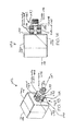
- FIG. 1 is a perspective view of a sensing assembly in accordance with one example embodiment of the present invention
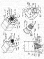
- FIG. 3 is a perspective view of a base portion of the sensing assembly of FIG. 1 ;
- FIG. 4 is cross-sectional cutaway view of a combination dimple/pocket arrangement employed by the sensing assembly of FIG. 1 ;
- FIGS. 5 and 6 are cross-sectional exploded views of the sensing assembly of FIG. 1 at different times during a process of assembling the base portion of the sensing assembly in relation to the housing portion of the sensing assembly;
- FIG. 7 is a further cross-sectional view of the sensing assembly of FIG. 1 after the conclusion of the assembly process of FIGS. 5 and 6 ;
- FIG. 8 is an additional cross-sectional view of the sensing assembly of FIG. 1 , where the housing and base portions of the assembly are assembled in a manner that is reversed relative to that shown in FIG. 7 (and FIG. 1 );
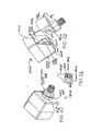
- FIG. 12 is a perspective view of the mounting bracket of FIG. 9 in combination with the sensing assembly of FIG. 11 but not yet fully attached, along with a further mounting component (a nut) that can be used to fixedly attach the sensing assembly and mounting bracket;
- FIG. 14 is a side elevation view of the sensing assembly of FIG. 13 ;
- FIG. 15 is a perspective view of a further example sensing assembly in accordance with another embodiment of the present invention.
- FIG. 16 is a perspective view of the mounting bracket of FIG. 9 attached to the sensing assembly of FIG 15 ;
- FIG, 17 is a cross-sectional view of portions of another example sensing assembly in accordance with yet another embodiment of the present invention.
- FIG. 18 is a perspective of a connector portion that is one of the portions of the sensing assembly of FIG. 17 ;
- FIG. 19 is a perspective of base portion that is one of the portions of the sensing assembly of FIG. 17 ;
- FIG. 20 is a perspective view of yet another example sensing assembly
- FIGS. 22-25 are perspective exploded views of other example sensing assemblies employing various mechanisms for attaching base portions of those sensing assemblies in relation to housing portions of those sensing assemblies that are different from a mechanism used in the sensing assembly of FIGS. 1-8 ;
- FIG. 26 is a further perspective view of the base portion of the sensing assembly of FIG. 25 .
- sensing assemblies and sensing assembly components are described below.
- the sensing assemblies and sensing assembly components described below should be understood as representative of any af a variety of types of sensing assemblies and components that can be used in a variety of applications.
- the sensing assemblies are proximity sensors,
- the sensing assemblies can be light sensing devices that can be implemented in conveyor systems as are often found in manufacturing and other commercial facilities in conjunction with assembly lines or the like.
- the sensing assemblies can include or encompass a variety of other types of assemblies, components or devices including, for example, other light-sensing devices (e.g., color-sensing devices, etc.), devices for sensing various other types of radiation (e.g., infrared, microwave, x-ray, etc.), position-sensing devices, acoustic sensors, vibration sensors, motion sensors such as accelerometers, orientation sensors involving gyroscopes, and numerous other types of sensing devices.
- the sensing assemblies can be suited for any of a variety of industrial, commercial, military, residential and other environments and/or be employed in connection with a variety of different applications.
- a sensing assembly 102 (in this example, a proximity sensor sensing assembly) includes a housing portion 104 with a cap 106 and a base portion 108. As shown, the housing and base portions 104, 108 together when assemble form a substantially cubic structures. Further as shown, jutting outward from a rear surface 110 of the sensing assembly 102 is a mounting portion 112 that, as will be discussed further with reference to FIG. 3 , is in the present embodiment a part of the base portion 108.
- the mounting portion 112 particularly extends outward along a central axis 114 of the sensing assembly 102 and includes a cylindrical threaded connector 116 at its far end and a multi-faceted mounting structure 118 positioned in between the threaded connector 116 and the rear surface 110 of the sensing assembly 102.
- the multi-faceted mounting structure 118 is octagonal in cross-section as viewed in a plane perpendicular to the central axis 114 (that is, the octagonal sides extend around the central axis).
- An outer diameter 120 of the multi-faceted mounting structure as measured between two diametrically-opposed outer points of that structure is substantially greater than (e.g., approximately double that of) the threaded connector 116.
- the sensing assembly 102 particularly can have dimensions of 40 millimeters (mm) by 40 mm (in terms of its outer surfaces that together form a cubic structure) while the outer diameter 120 of the multi-faceted mounting structure 118 can be 22 mm.
- the multi-faceted mounting structure 118 is octagonal, in other embodiments the cross-section of that structure can take the form of some other polygon having any arbitrary number of sides more than two (e.g., a hexagon).
- the cross-sectional shape of the multi-faceted mounting structure 118 will at least have five or more sides, and the shape will be that of a regular polygon having all interior angles being equal and all outermost points of the polygon lying along a shared circle.
- the outer shape of the multi-faceted mounting structure 118 is particularly configured to facilitate mounting of the sensing assembly 102 to a mounting bracket having a mounting hole with complementary multi-faceted internal surfaces.
- this structure can, depending upon the embodiment, either be rigidly affixed in relation to the mounting structure or alternatively can rotate relative to that mounting structure. In at least some embodiments where rotation is possible (and as further discussed below with respect to FIGS. 17-19 ), that rotation is limited to 360 degrees or less.
- one or more (in this case, multiple) connector pins 122 are exposed at a far end 124 of the threaded connector 116 (the pins are within a cylindrical interior of the threaded connector). It will be understood that, by way of the multiple connector pins 122.
- a complementary connector can be connected to (e.g., plugged in relation to) the threaded connector 116 and thus electrical signals (or, depending upon the embodiment, other signals such as optical signals) can be communicated from or to the sensing assembly to or from a remote device or location (not shown).
- the sensing assembly 102 is configured to receive and/or transmit sensing signals by way of a front surface 126 along the cap 106 of the housing portion 104, which is the side of the sensing assembly 142 that is opposite that of the rear surface 110.
- the housing portion 104, cap 106 and base portion 108 of the sensing assembly 102 can each be made of one or more plastic materials, and the housing portion can particularly be attached to the cap by a variety of methods induing press fit, gluing, or ultrasonic wielding methods.
- the base portion 108 can be made of a metal material.
- the housing portion 104 can be made of a metal material while the cap 106 is made of a plastic material, or the housing portion can be made of a metal material and/or the cap 106 can be made of the same or a different metal material such as stainless steel (or a titanium alloy). As will be discussed further with respect to FIGS.
- the housing portion 104 has a mating surface 128 by which it interfaces a complementary mating surface 130 of the base portion 108 such that, when the two portions arc assembled as shown in FIG. 1 , the two portions are in contact with one another along a junction 132.
- the junction 132 (and the mating surface 128, 130) extend along a plane that passes through the central axis 114 along a 45 degree angle and that is perpendicular relative to two diametrically-opposed side outer surfaces 134 and 136 of the sensing assembly 102 that each extend between the front surface 126 and the rear surface 110.
- the housing portion 104 and base portion 108 of the sensing assembly 102 of FIG. 1 are respectively shown disassembled from (independently of) one another to illustrate a mechanism by which those portions can be coupled (assembled) to one another.
- FIG. 2 a perspective view of the housing portion 104 is provided. As shown, in addition to the front surface 126, the rear surface 110, the side surfaces 134 and 136 (more particularly, portions of those rear and side surfaces, with the other portions being provided by the base portion 108), and the 45-degree-angled mating surface, 128 already discussed with respect to FIG. 1 .
- the housing portion 104 further includes a pair of mounting structures 200, 202 that protrude from the mating surface of the housing portion.
- the mating surface 128 in the present embodiment actually includes two half-surfaces 203 separated by a recessed packet 206.
- Each respective one of the mounting structures 200, 202 protrudes from a respective one of those half-surfaces 203.
- a round cable exit 208 is located in the center of the recessed pocket 206 between the half-surfaces 203 and mounting structures 200, 202 protruding therefrom.
- the mounting structures take a form similar to dovetails insofar as each of the mounting structures 200, 202 extends outward away from the malting surface 128 and generally first decreases slightly but then increases significantly in cross-sectional width as one proceeds farther away from the mating surface, such that while inner surfaces 210 of the mounting structures acre flat or substantially flat, outer surfaces 212 of the mounting structures are concave.
- each of the mounting structures 200, 202 extends about one-third of the length of the mating surface as measured along that axis, and each of the mounting structures is positioned at a respective location approximately midway along its respective mating surface.
- the mounting structures 200, 202 shown in FIG. 2 in other embodiments can take other forms, including for example the form of a traditional "V" shaped dovetail. Also it is possible that, in other embodiments, less than or more than two mounting structures will be present.
- the spherical dimple pockets 204 more particularly are symmetrically positioned on the mating surface 128 in terms of their positions relative to the four corners (or rounded corner edges) of the mating surface 128, and also symmetrical in terms of their positions relative to the mounting structures 200, 202.
- spherical pockets it should be understood that each of these recessed pockets can take a variety of other shapes depending upon the embodiment including, for example, a rectangular slot.
- the base portion 108 includes a pair of mounting structures 300, 302 that extend outward from within a recessed pocket 304 of the base portion up to the mating surface 130 so as to be flush with that mating surface.
- the mating surface 130 of the base portion 108 actually includes two half-surfaces 308 that are positioned on opposite sides of the recessed pocket 304, and the respective mounting structures 300, 302 are positioned along the recessed pocket on opposite sides thereof.
- the mounting structures 300, 302 take a form similar to dovetails insofar as the cross-sectional width of each of the mounting structures 300, 302, as one proceeds outward toward the mating surface 130, first decreases slightly but then increases significantly.
- the mounting structures 300, 302 which have the outer surfaces 212 that are concave facing outwardly away from the recessed pocket 206
- the mounting structures 300, 302 have concave surfaces 306 facing inwardly toward the recessed pocket 304 (as the mounting structures 300, 302 are provided inwardly of the mating surface 130, the mounting structures lack flat surfaces that would correspond to the flat surfaces 210 of the mounting structures 200, 202).
- the mounting structures 300, 302 are substantially complementary to the mounting structures 200, 202 in terms of their interfacing concave surfaces.
- each of the mounting structures 300, 302 extends about one-half of the length of the mating surface as measured along that axis, and each of the mounting structures is positioned at a first side 310 of the mating surface from which the mounting portion 112 protrudes rather than a second side 312 opposite the first side. Separating each of the mounting structures 300, 302 from the second side 312 are respective receiving portions 318 of the recessed pocket 304 that, as will be discussed further below with respect to FIGS.
- the mounting structures 200, 202 that protrude out from the mating surfaces 128 of the housing portion 104 while the mounting structures 300, 302 are substantially positioned inwardly of the mating surface 130 (aside from having outer edges flush with that mating surface)
- an opposite arrangement can be implemented where it is the mounting structures of the housing portion that have a substantially inward position and it is the mounting structures of the base portion that extend outward from the mating surface of that structure.
- the base portion 108 includes two raised spherical dimples (protrusions) 314 that are located proximate opposite corners (or rounded corner edges) of the mating surface 130 proximate the second side 312 of that mating surface, with one of the dimples on each respective one of the half-surfaces 308.
- the spherical dimples 314 are symmetrically positioned on the mating surface 130 in terms of their positions relative to the opposite corners of the mating surface along the second side 312. As discussed further with respect to FIGS.
- the spherical dimples 314 are positioned so as to engage (extend into) the two of the dimple pockets 204 of the housing portion 104 positioned along the first side 214 when the base portion 108 is coupled to the housing portion in a first orientation, and to engage (extend into) the other two of the dimple pockets 204 of the housing portion positioned along the second side 216 when the base portion is coupled to the housing portion in a second reverse orientation.
- the spherical dimples 314 are shaped to be complementary with respect to the recessed spherical dimple pockets 204 of the housing portion 104. Nevertheless, although shown as spherical dimple 314 in FIG. 3 , it should be understood that each of these dimples/raised protrusions can take a variety of other shapes depending upon the embodiment including, for example, a rectangular protrusion. Also, while the spherical dimples 314 in the present embodiment are symmetrically positioned, this need not be the case in all embodiments. For example, in one embodiment, one of the spherical dimples 314 could be closer to its respective corner than the other of the spherical dimples.
- the relative positioning of the dimple pockets of each respective pair of two dimple pockets either along the first side 214 or the second side 216 would be correspondingly adjusted so that the dimple pockets and dimples would be aligned.
- the base portion 108 additionally includes the mounting portion 112 with the octagonaliy-shaped multi-faceted mounting structure 118 as well as the threaded connector 116 with the pins 122 protruding from that mounting structure.
- the pins 122 also extend inwardly into (and are visible within) an interior epoxy pocket 316 that is recessed into the multi-faceted mounting structure 118.
- the interior epoxy pocket 316 can be filled with epoxy during assembly.
- FIG. 4 a cross-sectional, cutaway view is provided to show how one of the dimple pockets 204 of the housing portion 104 of FIGS. 1-2 can receive and engage one of the dimples 314 of the base portion 108 of FIGS. 1 and 3 when the housing portion and base portion are coupled to one another (as discussed further with respect to FIGS. 5-8 ).
- the raised dimple 314 extends (drops) into the dimple pocket 204 so that, in combination, a dimple locking mechanism 400 is formed that restricts sideways shifting of the base portion relative to the housing portion (e.g., shifting along the junction 132 of the mating surfaces 128, 130 of the housing and base portions).
- the restricting of shifting in this manner effectively locks the housing portion 104 in relation to the base portion 108 so that the two portions are substantially locked in place relative to one another in the absence of a sufficient disassembly force.
- the design of the dimple locking mechanism 400 is such that, when adequate force is applied, the dimple 314 will lift out of the recessed spherical dimple pocket 204 to release the locking mechanism, thereby allowing the base and housing portions 108 and 104 to be separated.
- dimple pockets 204 are on the housing portion 104 while the dimple 314 are on the base portion 108, in other embodiments the locating of the dimples and pockets can be reversed such that the dimples are on the housing portion and the dimple pocket are on the base portion. Also, just as the dimples can take on other shapes and forms as described above, so to can the dimple pockets (typically, though not always, the shapes of the dimples and pockets will be complementing).
- FIGS. 5-8 the manner of assembling of the housing portion 104 and base portion 108, by way of the mounting structures 200, 202, 300, 302 and dimple mechanisms 400 achieved by the recessed dimple pockets 204 and raised dimples 314, is illustrated in greater detail. Also, certain internal components of the sensing assembly 102 within the housing portion 104 and base portion 108 are shown in more detail. Referring particularly to FIG, 5 , a cross-sectional view of the sensing assembly 102 taken along the central axis 114, when the base portion 108 is exploded from the housing portion 104, is provided. As shown, the sensing assembly 102 internally includes a coil assembly 500, which can include for example a.
- a coil assembly 500 which can include for example a.
- the coil assembly 500 is attached to an internal surface 502 of the front surface 126 of the cap 106, which constitutes the sensing face of the sensing assembly 102.
- a copper or brass shield 504 surrounds the coil assembly 500 along the sides and/or the back to facilitate some sensing modes, such as the shielded sensing mode, or to improve performance.
- wires 506 connect the coil assembly 500 to a printed circuit board (PCB) 508 containing sensing circuitry.
- the printed circuit board 508 containing the sensing circuitry is soldered (by way of solder 510) at a right angle to another structure (which can be another PCB) 512 located behind the coil assembly 500.
- another structure which can be another PCB
- the sensing circuitry can be located on this other structure (in which case it can be a PCB) 512.
- a cable (or flex circuit) 514 that is soldered to the PCB 508 passes through the cable exit 208 of the housing portion 104 and into the base portion 108, where it is further soldered to (or otherwise attached to) the pins 122 in the threaded connector 116, thereby allowing for a flexible connection of the base portion/pins with the interval electronic circuitry of the housing portion 104.
- an adhesive can be used near the cable exit 208 to temporarily fix the cable 514 in relation to the housing portion 104.
- a grommet (not shown) can also or instead be used to provide a seal between the cable and the cable exit.
- the epoxy pocket 316 in the multi-faceted mounting structure 118 of the base portion 108 is filled with epoxy potting to seal the pin 122 and connections between the pins and the cable 514 from the environment.
- an internal volume 516 within the housing portion 104 (and cap 106) is also filled with epoxy potting, or similar material, to facilitate heat dissipation from the sensing assembly 102 (particularly from the electronic circuitry) and to provide structural rigidity that helps the sensing assembly to withstand mechanical shock and vibration.
- FIG. 5 an example manner of assembling the base portion 108 in relation to the housing portion 104 is illustrated.
- the base portion 108 in a first step, is positioned and moved in the direction of arrows 518 so that the mating surface 130 approaches and ultimately abuts the mating surface 128 of the housing portion 104 so as to arrive at a relative positioning as shown in FIG. 6 and form the junction 132 between those mating surfaces.
- the base portion 108 is shifted relative to the housing portion 104 along the junction 132 such that the mounting structures 200, 202 of the housing portion (one of which, the mounting structure 200, is visible in FIGS.
- the mounting structures 200, 202 do not yet engage the mounting structures 300, 302 (one of which, the mounting structure 300, is visible in FIGS. 5-6 ) of the base portion. Rather, the mounting structures 200, 202 are shifted relative to the mounting structures 300, 302 along the direction of an arrow 600 parallel to the junction 132, such that the mounting structures 200, 202 extend into the receiving portions 318 of the base portion 108 (in particular, the mounting structure 200 is shown to extend into a complementary one of the receiving 318 in FIG. 6 ).
- the assembly process is then completed by sliding the base portion relative to the housing portion along the junction 132 in the direction indicated by the arrow 600 of FIG. 6 .
- This causes the mounting structures 300, 302 of the base portion 108 to engage the mounting structures 200, 202 of the housing portion 104, as shown in. FIG. 7 .
- the dimples 314 of the base portion 104 particularly engage the two of the spherical dimple pockets 204 of the housing portion 104 that are closest to the second side 216.
- the dimples 314 on the base portion 108 are seated in the recessed spherical dimple pockets 204 of the housing portion 104 in a manner that prevents unintended separation of the housing and base portions.
- the dimples/recessed pockets can also be designed to provide a slight interference fit that will also aid in preventing unintentional separation.
- the outer (concave) surfaces 212 of the mounting components 200, 202 do not fully overlap the concave (inner) surfaces 306 of the mounting components 300, 302 even when the base portion 108 is fully assembled to (and aligned with) the housing portion 104. Rather, given the design of the mounting components 200, 202, 300, 302, portions af the concave surfaces 306 remain out of contact with the outer surfaces 212 and likewise portions of the surfaces 212 remain out of contact with the surfaces 306.
- the housing portion 104 and base portion 108 are solidly affixed with respect to one another when in the position shown in FIG. 7 .
- FIGS. 5-7 show the inner surface 210 rather than the outer surface 212 of the mounting structure 200 of the housing portion 104, it is the outer surface 212 (as shown in FIG. 2 ) that engages the concave surface 306 of the mounting structure 300 of the base portion 108.
- FIG. 8 illustrates particularly a second version of the sensing assembly, shown as a sensing assembly 802, in which the base portion 108 is oriented in this opposite manner-relative to the housing portion 104. Assembly is accomplished in substantially the same manner as that illustrated by FIGS.
- the base portion 108 initially approaches the housing portion 104 having an orientation that is reversed 180 degrees relative to the orientation shown in FIGS. 5-6 (about an axis perpendicular to the junction 132) and, once the base portion mating surface 130 is in contact with the housing portion mating surface 128, the base portion is slid in a direction corresponding to an arrow 804 shown in FIG. 8 to be opposite the direction of the arrow 600 of FIG. 6 .
- the respective mounting components 200, 202, 300, 302 are reversed in terms of their relative contact relative to that of the sensing assembly 102. That is, the mounting component 200 is in contact with the mounting component 302 (rather than the mounting component 300) as shown in FIG. 8 while the mounting component 202 is in contact with the mounting component 300 rather than the mounting component 302 (this is not shown in FIG. 8 ). Further, while in the (sensing assembly 102 the dimples 314 are engaged with the two recessed dimple pockets 204 that are proximate the second side 216 rather than the first side 214, in the sensing assembly 802 as shown in FIG. 8 the dimples 314 are engaged with the two recessed spherical dimples pockets 204 that are proximate the first side 214 of the housing portion 104 rather than the second side 216.
- the front surface 126 (sensing face) of the sensing assembly 102 is perpendicular to the central axis 114 extending through the mounting portion 112/threaded connector 116 as shown in FIG. 7
- the front surface 126 (sensing face) of the sensing assembly is parallel to an axis 806 extending through the mounting portion 112/threaded connector 116.
- the mounting portion 112/threaded connector 116 jut out from the sensing assembly 102 in a manner diametrically opposed to the directional orientation of the sensing face (that is, the direction out away from the front surface 126), in the sensing assembly 802 the mounting portion 112/threaded connector 116 jut out from the sensing assembly in a direction at a right angle relative to the directional orientation of the sensing face.
- FIG. 9 a perspective view is provided of an exemplary mounting bracket 900 that can be used to affix the sensing assemblies 102, 802 of FIGS. 1-8 to a support structure such as a wall (not shown).
- the mounting bracket 900 is described below as a component separate from the sensing assemblies 102, 802, it will be understood that the mounting bracket can also itself be considered a sensing assembly component such that, when one af the sensing assemblies 102, 802 is affixed to the mounting bracket, the overall combination can itself be considered a sensing assembly.
- the mounting bracket 900 particularly includes a multi-faceted mounting hole 902 that in the present embodiment has an internal surface 904 having multiple facets intended to be complementary to hose of the multi-faceted mounting structure 118 discussed above.
- the internal surface 904 of the multi-faceted mounting hole 902 is in the shape of an octagon, so as to complement the octagonal shape of the multi-faceted mounting structure 118.
- the internal surface of the multi-faceted mounting hole can have more or less facets than eight (e.g., six) and, although the present embodiment employs a regular polygon shape, in other embodiments the shape need not be that of a regular polygon.
- the mounting bracket 900 further includes support gussets 908 extending between the support platform and a support surface 909 extending substantially perpendicularly with respect to the support platform.
- the support gussets 908 are provided to lend additional structural rigidity to the mounting bracket 900.
- the eight facets of each of the multi-faceted mounting structure 118 and mounting hole 902 allow the sensor (sensing face/front surface 126) to be positioned in 8 different rotational orientations, each 45 degrees apart, when the sensing face directional orientation is perpendicular to the axis 806 extending through the mounting portion 112 as shown in FIG. 8 .
- the sensor (sensing face/front surface 126) can take on a ninth orientation if one reverses the base portion 108 relative to the housing portion 104 so that the sensing assembly 802 is converted into the sensing assembly 102 where the sensing face directional orientation is positioned along the central axis 114 extending through the mounting portion 112 as shown in FIGS. 1 and 7 .
- a further advantage associated with the sensing assemblies 102, 802 is that assembly of the housing portion 104 and base portion 108, and reorientation of the housing portion relative to the base portion (that is, from the sensing assembly 102 to the sensing assembly 802 or vice versa) can be accomplished without using additional tools or components.
- the use of the mounting structures 200, 202, 300, 302 and locking mechanisms 400 allows for the base portion and housing portion to be assembled with one another simply by way of pressing those portions together and shifting them so that the two components are aligned and locked into place.
- the present arrangement is advantageous because it allows for assembly of sensing assembly components without the use of special fastening/assembly components or associated tools, and also allows for the assembly process (and reorientation of the base portion relative to the housing portion) to be performed in a simpler, easier, and faster manner.
- FIG. 10 a further embodiment of a sensing assembly 1002 and complementary mounting bracket 1000 are shown (again, the sensing assembly and mounting bracket can together be considered a sensing assembly as well).
- the housing portion 104 (and cap 106) of the sensing assembly 1002 is the same as that of the sensing assemblies 102, 802, a base portion 1008 differing from the base portion 108 is employed.
- the base portion 1008 includes a mounting portion 1012 that differs from the mounting portion 112 described above in that, while still including the threaded connector 116, instead employs a threaded mounting structure 1018 in place of the multi-faceted mounting structure 118.
- the sensing assembly 1002 particularly can be coupled to (affixed to) the mounting bracket 1000 by way of a mounting nut (e.g., a hex nut) 1016 that is complementary in its threads to the threads of the threaded mounting structure 1018.
- a mounting nut e.g., a hex nut
- the threaded mounting structure 1018 can be of any thread size including any thread size commonly used in the industry, such as 18mm threads.
- the thread diameter of the threaded mounting structure 1018 can also be sized to correspond to the 22mm mounting diameter of some conventional cubic (or rectangular) proximity sensor mounting brackets currently on the market to allow for backwards compatibility.
- the mounting bracket 1000 additionally has a further surface i 019 extending substantially perpendicularly away from the support surface. Further, four mounting holes 1020 are provided through the further surface 1019 through which bolts or other fasteners can be inserted to allow for attachment of the mounting bracket 1000 to another support structure such as a wall (not shown).
- the mounting bracket 1000 in the present embodiment has four mounting holes arranged in a pattern generally accepted by the industry, although the number of mounting holes and their arrangement can vary depending upon the embodiment (and, indeed, other fastening devices or manners of fastening the mounting bracket to another support structure can be employed in other embodiments).
- the further sensing assembly 1102 is similar to each of the sensing assemblies 102 and 1002 but represents a combination of the two. That is, the further sensing assembly 1102 continues to employ the housing portion 104 (and cap 106) but has a base portion 1108 having a mounting portion 1112 that includes not only the threaded connector 116 but also both a first multi-faceted mounting structure 1118 identical to or substantially identical to (e.g., in terms of its octagonal facets, diameter and axial length) the multi-faceted mounting structure 118 of the base portion 108, and also a threaded mounting structure 1116 identical to or substantially identical to (e.g., in terms of threading features, diameter, and axial length) the threaded mounting structure 1018 of the base portion 1008 of the sensing assembly 1002.
- a first multi-faceted mounting structure 1118 identical to or substantially identical to (e.g., in terms of its octagonal facets, diameter and axial length) the multi-faceted mounting structure 118 of the base portion 108
- the threaded mounting structure 1116 in particular can have any thread size commonly used in the industry, such as 18mm threads.
- the threaded mounting structure 1116 is positioned between the multi-faceted mounting structure 1118 and the threaded connector 116, while the multi-faceted mounting structure 1118 is positioned between the threaded mounting structure 1116 and a rear surface 1110 of the sensing assembly 1102.
- the threaded connector 116 and threaded mounting structure 1116 extend outward beyond the support platform 906 of the mounting bracket 900 on the other side of that support platform opposite that which is in contact with the rear surface 1110 of the sensing assembly 1102.
- the mounting nut 1016 employed in the arrangement of FIG. 10 can also be used to secure the threaded mounting structure 1116 and sensing assembly 1102 in relation to the mounting bracket by threading the mounting nut onto the threaded mounting structure and tightening the mounting nut.
- the threaded connector 1156 although slightly different from the threaded connector 116 (e.g., because the threads are only at the end of the threaded connector rather than along its entire axial length), still has the pins 122 therewithin and, in other embodiments, can be identical to the threaded connector 116.
- the threaded mounting structure 1168 of FIGS. 13-14 differs from the threaded mounting structure 1018 of FIG. 10 in several manners.
- the threaded mounting structure 1168 has a recessed undercut 1169 spaced between first and second axial portions 1170 and 1171 of the mounting structure that are threaded, where the first axial portion 1170 is positioned axially along the central axis 114 adjacent to the housing portion 104 while the second axial portion 1171 is positioned axially farther down the central axis 114 and is the portion of the mounting structure from which the threaded connector 1156 extends.
- the threaded mounting structure 1018 is generally shaped in the form of a right circular cylinder
- the threaded mounting structure 1168 instead has a quasi-octagonal shape in cross-section (as viewed in a plane perpendicular to the central axis 114). More particularly as shown, the threaded mounting structure 1168 particularly includes four flat sides or flats 1172 alternating with four rounded corner formations or rounds 1173. Each of the four flats 1172 in particular is positioned at a location about the central axis 114 that is 90 degrees apart from the location of the next successive one of the flats.
- the four flats 1172 particularly form two pairs of the flats, with the flats of each pair being parallel to and positioned opposite one another about the central axis 114.
- the threaded mounting structure 1168 is quasi-octagonal (rather than fully octagonal) in shape insofar as the flats 1172 are similar in shape and position to four corresponding facets/sides of the multi-faceted mounting structure 118 of FIG. 1 , but the rounds 1173 extend in a convex manner outward beyond where the surfaces of the remaining four facets/sides of the multi-faceted mounting structure 118 are positioned.
- the flats 1172 are only partly threaded (and needed not be threaded at all).
- the additional sensing assembly 1152 is particularly configured to be supported by a modified version of the mounting (support) bracket 900 shown in FIG. 9 .
- the mounting (support) bracket used in connection with this threaded mounting structure 1168 can be identical to the mounting (support) bracket 900 of FIG. 9 except insofar as the mounting hole within that bracket should, rather than being octagonal as is the mounting hole 902 of FIG. 9 , be "quasi-octagonal" with facets that are alternatingly flat and rounded such that the mounting hole is complementary in shape relative to the shape of the threaded mounting structure 1168.
- the rounds 1173 are curved in a manner so as to allow the mounting nut to be screwed onto the threaded mounting structure 1168.
- the particular mounting nut used can have an inner diameter (of its threads) that is identical or substantially identical to the outer diameter of the rounds 1173 (of the threads of the rounds) so that the mounting nut is complementary relative to the rounds.
- the threaded mounting structure 1168 in the embodiment of FIGS. 13-14 is quasi-octagonal in shape, in alternate embodiments it can take other shapes as well.
- three flats can be positioned in an alternating manner relative to three rounds, to form a quasi-hexagonal shape.
- still other variations are possible. Indeed, any arbitrary number of flats and rounds can be present.
- the flats can be replaced with surfaces of other shape.
- the flats or other shapes are recessed so as to not extend outward beyond a circumference corresponding to the threads of the rounds since, desirably, the round(s) of these embodiments are threaded and particularly accommodate attachment of a mounting nut/ring.
- the support bracket can be attached to the threaded mounting structure 1168 in a locked manner that prevents relative rotation of the support bracket and the mounting structure.
- such designs can limit attachment of the threaded mounting structure to only those support brackets that have complementary mounting holes, thus preventing undesirable or unintended coupling of threaded mounting structures to support brackets that are not appropriate for supporting those threaded mounting structures (and vice-versa).
- a mounting nut can be screwed onto the threaded connector of a sensing assembly fully so as to lock the sensing assembly in place relative to a support bracket extending between the mounting nut and remainder of the sensing assembly, and then also an electrical connector (e.g., a cable) can further be screwed onto the threaded connector (at a location at or more proximate to the tip of the threaded connector) to allow for a desired electrical connection to be achieved by way of coupling that electrical connector to the electrical connector portion(s) (e.g., the pins) of the threaded connector.
- an electrical connector e.g., a cable
- the multi-faceted mounting structure 1318 additionally includes two arrow shaped snaps 1320 that are built into and extend outward from the multi-faceted mounting structure along (but spaced from) the threaded connector 116, in a direction parallel to a central axis 1314 of the sensing assembly 1302.
- the snaps 1320 are located on opposite sides of the multi-faceted mounting structure 1318 and each face outward such that respective ramped snap face portions 1322 of the snaps are located on the outer (rather than inner) surfaces of the snaps 1320.
- gaps 1324 are formed along portions of the snaps 1320 between the snaps and that mounting structure, allowing the snaps to flex radially inward toward the central axis 1314 when inwardly-directed radial pressure is applied to the ramped snap face portions 1322.
- those snap face portions snap outwardly away from the central axis 1314 such that outer portions of those snap face portions overhang the mounting bracket support platform 906 such that the snap face portions cannot be pulled back out through the multi-faceted mounting hole 902. That is, after the ramped snap face portions 1322 have passed through the mounting hole 902 in the bracket 900, the snaps 1320 spring outward to allow the ramped snap face portions to secure the sensing assembly 1302 to the bracket. Thus, at that point, the snaps 1320 and thereby the entire sensing assembly 1302 is locked in place relative to the mounting bracket 900.
- the ramped snap face portions 1322 need to be pressed inwardly toward the central axis 1314 (and toward one another) to release the snaps relative to the mounting bracket 900, such that the mounting portion 1312 including the snaps 1320 can be pulled back out through the multi-faceted mounting hole.
- the use of the snaps 1320 thus provide a fast and convenient mechanism for installation and removal of the sensing assembly 1302 relative to the mounting bracket 900 without the need for additional tools or fastening devices.
- the sensing assemblies 1002, 1102, and 1302 shown in FIGS. 10, 11 , and 15 respectively, although having the respective base portions 1008, 1108, and 1308 that each differ from the base portion 108 of FIG. 1 , nevertheless can and in the present embodiments do include the coupling mechanisms discussed with respect to FIGS. 1-8 by which the base portions are coupled to the housing portion 104 of those sensing assemblies.
- the base portions 1008, 1108, and 1308 can achieve the same benefits as the base portion 108 in terms of being capable of attachment and reorientation relative to the housing portion 104 in the multiple manners illustrated in FIGS. 5-8 .
- FIGS. 17-19 although in some embodiments the threaded connector (e.g., the threaded connector 116 of FIG. 1 ) is fixedly attached to the remainder of the base portion (e.g., the base portion 108) and/or the remainder of the mounting portion to which the threaded connector is attached (e.g., the mounting structure 118 of the mounting portion 112), in other embodiments the threaded connector is rotatable relative to the base portion and/or other portion(s) of the mounting portion.
- FIG. 17 in particular shows a cross-sectional view of a sensing assembly 1502 that is identical to the sensing assembly 102 of FIG.
- FIG. 18 additionally shows the threaded connector 1516 when removed from the remainder of the base portion 1508/mounting portion 1512, while FIG. 19 shows a perspective view of the base portion 1508 without the threaded connector 1516 present therein. It should be noted that the particular cross-section shown in FIG.
- 17 is a cross-section taken along a plane perpendicular to the outer side surfaces of the housing portion (e.g., perpendicular to the surfaces 134 and 136 of FIG. 1 ), where the plane is coincident with a central axis 1517 of the sensing assembly 1502 (e.g., the central axis corresponding to the central axis 114 of FIG. 1 ), and the cross-sectional view is only provided from the tip of the mounting portion 1512 (the threaded, connector 1516) inward to a cutaway line 1519 proximate the junction between the mounting portion and the housing portion 104.
- the threaded connector 1516 be rotatable, it is still desired that the threaded connector be retained axially within the remainder of the mounting portion 1512 that is, with respect to a multi-faceted mounting structure 1518 of the mounting portion.
- snaps 1520 with flat end faces (heads) 1522 are built into the base portion 1508, and particularly extend axially within the multi-faceted mounting structure 1518.
- the snaps 1520 more particularly are built into an annular wall 1506 (see FIG. 19 ) protruding inwardly from the end of the multi-faceted mounting structure 1518 toward the main body of the base portion 1508.
- a circumferential groove 1524 and adjacent circumferential rim 1525 are formed adjacent to one another along the outer surface of the threaded connector 1516, axially midway between threads 1526 formed at one end of the threaded connector (the end from which the pins 122 are accessible) and the other end of the threaded connector that is to be retained within the multi-faceted mounting structure 1518.
- the circumferential rim 1525 particularly is closer to the threads 1526 than the circumferential groove 1524.
- the circumferential rim 1525 passes along the radially inwardly-facing surfaces of the snaps 1520 until it passes the flat end faces 1522.
- a pocket 1532 in the back of the threaded connector 1516 (proximate the end of the threaded connector opposite the end having the threads 1526) is filled with epoxy potting to seal soldered connections 1534 between the cable 514 and the connector pins 122.
- the threaded connector 1516 and the base portion 1508 are provided such that, although the threaded connector is able to rotate about the central axis 1517 relative to the base portion, it is not able to rotate more than 360 degrees. This is desirable to limit the degree of twisting experienced by the cable 514 (and possibly any external connector to which threaded connector is linked).
- the threaded connector 1516 has a protrusion 1602 at its end opposite the end on which are provided the threads 1526 (that is, the protrusion 1602 is at the end of the threaded connector that interfaces the multi-faceted mounting structure 1518).
- a protrusion 1702 extending upwards and radially outwards from the top of the annular wall 1506 is also provided, where the top of the annular wall is the axially-innermost portion of the annular wall that is closest to the housing portion 104 when the housing portion 104 and base portion 1508 are assembled.
- the protrusion 1602 rests upon the top of the annular wall 1506.
- the threaded connector 1516 When so positioned, the threaded connector 1516 is free to rotate (in either clockwise or counterclockwise directions) up to but not beyond rotational positions at which the protrusion 1602 engages the protrusion 1702, which limits the rotation of the threaded connector to a maximum of 360 degrees (more accurately, to slightly less than 360 degrees).
- sensing assemblies such as those described above can be affixed to mounting brackets in a variety of manners.
- a number of the multi-faceted mounting structures discussed above e.g., the mounting structures 118 and 1118 discussed above
- an undercut multi-faceted or round
- Such an undercut can take a form that is similar or identical to that of the undercut 1169 of FIGS. 13-14 . Further in this regard, FIG.
- FIG. 20 in particular shows a sensing assembly 1802 that is identical to the sensing assembly 102 except insofar a base portion 1808 of the sensing assembly includes an undercut 1804 (or groove) formed around a multi-faceted mounting structure 1818 of that base portion.
- the undercut in this embodiment is axially midway along the mounting structure 1818.
- FIG. 21 provides a further cross-sectional cut-away view of the multi-faceted mounting structure 1818/base portion 1808 of the sensing assembly 1802 mounted in relation to a mounting bracket 1900 that is identical to the mounting bracket 900 of FIG.
- components of another sensing assembly 2002 include a housing portion 2004 and a base portion 2008.
- the housing portion 2004 of the sensing assembly 2002 includes two fins 2006 that protrude from the main body of the housing portion, away from a 45-degree-angle mating surface 2007 of the housing portion that corresponds to the mating surface 128 of FIG. 1 .
- the two fins 2006 in particular extend in directions substantially parallel to side surfaces, 2009 of the housing 2004, but are positioned slightly in wards of those side surfaces (that is, inwardly toward one another).
- Locking protrusions (one of which is shown) 2010 extend outwards from outer side surfaces 2011 (again one of which is shown) of the fins 2006.
- the locking protrusions 2010 can have a variety of shapes such as, for example, that of a rounded rectangle as shown.
- the locking protrusions 2010 are configured to mate with complementary holes (one of which is shown) 2012 located in side walls 2013 of the base portion 2008 of the sensing assembly.
- the side walls 2013 of the base portion 2008 can flex to receive the locking protrusions 2010.
- the fins 2006 protruding from the housing portion 2004 are inside the base portion 2008.
- an additional sensing assembly 2102 employs another exemplary locking mechanism.
- the sensing assembly 2102 is identical to the sensing assembly 2002 of FIG. 22 in that it again employs on a, housing portion 2104 two fins 2106 (extending from a 45-degree-angle mating surface 2107) with locking protrusions 2110 that are configured to engage complementary holes 2112 within side walls 2113 of a base portion 2108.
- the fins 2106 are positioned slightly inwardly of side surfaces 2109 of the housing portion 2104.
- the locking protrusions 2110 are spherical protrusions that extend outwards from the fins 2106, and the complementary holes 2112 located in the side walls 2113 are round holes.
- the fins 2106 protruding from the housing portion 2104 can flex to allow the spherical locking protrusions 2110 to fit into the holes 2112 in the base portion 2108.
- the sensing assembly 2102 is fully assembled, the fins 2106 protruding from the housing portion 2104 are inside the base portion 2108.
- FIG. 24 another sensing assembly 2202 having another exemplary locking mechanism is shown,
- two fins 2206 protrude from a 45-degree-angle mating surface 2207 of a housing portion 2204 and are not only parallel to but coincident with and extensions of exterior side surfaces 2209 of the housing portion.
- holes 2210 are located in the fins 2206 to accept complimentary protrusions (one of which is shown) 2212 that extend outwards from side surfaces (one of which is shown) 2213 of a base portion 2208.
- the holes 2210 and protrusions 2212 can have a variety of shapes depending upon the embodiment, and in the present embodiments both are round (e.g., the protrusions can be spherical or cylindrical).
- the fins 2206 protruding from the housing portion 2204 can flex to allow the protrusions 2212 to fit into the holes 2210 in the fins 2206. When assembled, the base portion 2208 fits between the fins 2206.
- FIGS. 25-26 a further example sensing assembly 2302 is shown employing another exemplary locking mechanism.
- FIG. 25 shows both the housing portion of the sensing assembly 2302, which again is the housing portion 2204 of 24, and a base portion 2308 of the sensing assembly.
- FIG. 26 shows the base portion 2308 again in more detail from a different perspective view.
- the two fins 2206 protrude from the main body of the housing portion 2204 along the exterior side surfaces 2209 and include the holes 2210. which again are located in the fins to accept complimentary protrusions 2312 formed on the base portion 2308.
- FIGS. 24 in contrast to the embodiment of FIG. 24 , in FIGS.
- the complementary protrusions 2312 formed on the base portion 2308 are formed on snaps 2314 that are formed in the base portion.
- the snaps 2314 particularly are elongated extensions formed within side walls 2313 of the base portion 2308, where one end of each snap is integral with the remainder of the side wall in which it is formed and the snap extends from that one end, separated from the rest of the side wall along the remainder of the length of the snap, by way of cuts 2316.
- the protrusions 2312 are formed on the snaps 2314 at their far ends, opposite the ends that are integral with the remainders of the respective sidewalls 2313.
- the holes 2210 and protrusions 2312 that extend from the snaps 2314 can have a variety of shapes, and in the present embodiment are shown to be round (or spherical or cylindrical in the case of the protrusions).
- the fins 2206 protruding from the housing portion 2204 can be made rigid to prevent flexing, That is, it is the snaps 2314 in the sidewalls 2313 of the base portion 2308 that can flex to allow the raised protrusions 2312 at the far ends of the snaps to engage with the holes 2210 in the housing fins 2206.
- the base portion 2308 of the sensing assembly 2302 fits between the fins 2206.
- the holes 2012. 2112, and 2210 of FIGS. 22-25 are shown to extend fully through the walls in which the holes are formed in alternate embodiments, the holes need not extend all of the way through the walls but rather can simply be indentations formed in the wall surfaces that receive the complementary protrusions.
- surfaces or edges of the base portions 2008, 2108, 2208, and 2308 can still be considered mating surfaces that are in contact with, and complement, the mating surfaces 2007, 2107, 2207, and 2307 of the corresponding housing portions 2004, 2104, 2204, and 2304, respectively.
- surfaces or surface portions e.g., simply the edges of the side walls 2013
- these surfaces or surface portions of the base portion 2008 can also be considered mating surfaces that complement the mating surface 2007.
Landscapes
- Physics & Mathematics (AREA)
- General Physics & Mathematics (AREA)
- Connection Of Plates (AREA)
- Casings For Electric Apparatus (AREA)
Applications Claiming Priority (2)
| Application Number | Priority Date | Filing Date | Title |
|---|---|---|---|
| US201061428921P | 2010-12-31 | 2010-12-31 | |
| US13/315,992 US9157772B2 (en) | 2010-12-31 | 2011-12-09 | Sensing assembly components and methods of assembling, mounting and orientating same |
Publications (3)
| Publication Number | Publication Date |
|---|---|
| EP2472234A2 true EP2472234A2 (de) | 2012-07-04 |
| EP2472234A3 EP2472234A3 (de) | 2015-08-26 |
| EP2472234B1 EP2472234B1 (de) | 2018-06-13 |
Family
ID=45440417
Family Applications (1)
| Application Number | Title | Priority Date | Filing Date |
|---|---|---|---|
| EP12150026.8A Not-in-force EP2472234B1 (de) | 2010-12-31 | 2012-01-02 | Sensorbaugruppenkomponenten und Verfahren zu deren Montage, Anbringung und Ausrichtung |
Country Status (2)
| Country | Link |
|---|---|
| US (1) | US9157772B2 (de) |
| EP (1) | EP2472234B1 (de) |
Cited By (1)
| Publication number | Priority date | Publication date | Assignee | Title |
|---|---|---|---|---|
| WO2017215915A1 (de) * | 2016-06-14 | 2017-12-21 | Robert Bosch Gmbh | Sensorvorrichtung und verfahren zur herstellung einer sensorvorrichtung |
Families Citing this family (7)
| Publication number | Priority date | Publication date | Assignee | Title |
|---|---|---|---|---|
| AU2003902259A0 (en) * | 2003-05-13 | 2003-05-29 | Telezygology Inc. | Improved assembly system |
| KR101685890B1 (ko) * | 2015-01-20 | 2016-12-28 | 현대자동차주식회사 | 음파 센서 장치 |
| EP4077820B1 (de) | 2019-12-19 | 2024-08-14 | Emerson Electric Co. | Konfigurierbare wasserhahnvorrichtung und verfahren zur implementierung und zum betrieb derselben |
| USD988474S1 (en) | 2020-10-01 | 2023-06-06 | InSinkErator LLC | Faucet apparatus |
| USD988475S1 (en) | 2020-10-01 | 2023-06-06 | InSinkErator LLC | Faucet apparatus |
| FR3128067A1 (fr) * | 2021-10-08 | 2023-04-14 | Sc2N | Capteurs de position |
| DE102022131236A1 (de) * | 2022-11-25 | 2024-05-29 | Turck Holding Gmbh | Elektrisches Endgerät, Herstellungsverfahren und Justierungsverfahren |
Family Cites Families (28)
| Publication number | Priority date | Publication date | Assignee | Title |
|---|---|---|---|---|
| DE920919C (de) | 1942-03-04 | 1954-12-02 | Aeg | Isoliergehaeuse oder Isolierabdeckung mit Schauglas, insbesondere fuer elektrische Geraete |
| CA1192616A (en) | 1981-06-08 | 1985-08-27 | Canadian National Railway Company | Radio channel visual identification system |
| US4785240A (en) | 1984-10-01 | 1988-11-15 | Square D Company | Proximity switch |
| JP2706776B2 (ja) | 1988-02-10 | 1998-01-28 | 株式会社三協精機製作所 | 磁気感応素子用のホルダー |
| FR2643640A1 (en) | 1989-02-24 | 1990-08-31 | Telemecanique Electrique | Proximity detector with state indication |
| DE3918874A1 (de) | 1989-06-09 | 1990-12-13 | Erben Hans Wilhelm | Signal-einrichtung im bewachungsgewerbe zur warnung von gefahren an bewachten baustellen im betrieb |
| GB2244336B (en) | 1990-05-21 | 1994-11-16 | Turck Werner Kg | Electronic proximity switch |
| US5543782A (en) | 1993-11-16 | 1996-08-06 | Protex International Corp. | Security device for merchandise and the like |
| DE19512915C1 (de) | 1995-03-26 | 1996-08-29 | Pepperl & Fuchs | Vorrichtung zum Umlenken von Licht in Vorzugsrichtungen eines Licht aussendenden Leuchtkörpers und damit ausgerüstetes elektrisches Verbindungsteil, wie Stecker oder Buchse |
| US5698975A (en) | 1996-04-10 | 1997-12-16 | Allen-Bradley Company, Inc. | Mounting and coupling arrangement for a proximity sensor |
| USD391182S (en) | 1996-08-23 | 1998-02-24 | Werner Turck Gmbh & Co. Kg | Indicator for locating proximity sensors |
| JP3570662B2 (ja) | 1997-04-14 | 2004-09-29 | 矢崎総業株式会社 | 低挿入力コネクタ |
| US7370983B2 (en) | 2000-03-02 | 2008-05-13 | Donnelly Corporation | Interior mirror assembly with display |
| DE10035996B4 (de) | 2000-07-25 | 2004-03-04 | Balluff Gmbh | Näherungsschalter |
| DE10038001B4 (de) * | 2000-08-04 | 2008-09-18 | Balluff Gmbh | Sensoranordnung |
| US7063537B2 (en) | 2002-08-15 | 2006-06-20 | Smar Research Corporation | Rotatable assemblies and methods of securing such assemblies |
| DE20217773U1 (de) | 2002-11-18 | 2003-01-30 | Pepperl + Fuchs GmbH, 68307 Mannheim | Gehäuse zur Aufnahme eines elektrischen Schaltgerätes oder Sensors mit einer Anzeigeeinrichtung zur Anzeige von verschiedenen Schaltzuständen |
| DE20301144U1 (de) | 2003-01-24 | 2004-06-03 | Pepperl + Fuchs Gmbh | Befestigungsvorrichtung, bestehend aus einem Befestigungssockel und einem elektrischen Gerät |
| US7047823B2 (en) * | 2004-06-23 | 2006-05-23 | Texas Instruments Incorporated | Apparatus for mounting electronic module assembly in sensor |
| US7241181B2 (en) * | 2004-06-29 | 2007-07-10 | Pulse Engineering, Inc. | Universal connector assembly and method of manufacturing |
| US20060280657A1 (en) | 2005-06-13 | 2006-12-14 | Farina Edward F | Snap fit sensor mounting bracket |
| US7737843B2 (en) | 2005-12-23 | 2010-06-15 | Invue Security Products Inc. | Programmable alarm module and system for protecting merchandise |
| DE102006007951B4 (de) | 2006-02-21 | 2013-08-29 | Rittal Gmbh & Co. Kg | Sensorvorrichtung mit Motageeinheit |
| CA2905672C (en) | 2006-12-14 | 2018-09-04 | Hunter Douglas Industries B.V. | Roller blind mounting system and parts therefor |
| DE102008042314B4 (de) | 2008-09-24 | 2012-12-13 | Ifm Electronic Gmbh | Messumformer zur Verbindung eines Sensorelements mit einer externen Einheit, und elektronischer Stecker zum Anschluss an ein elektronisches Gerät |
| JP4908478B2 (ja) | 2008-10-15 | 2012-04-04 | 長野計器株式会社 | 物理量測定用表示器 |
| DE202009009048U1 (de) | 2009-06-30 | 2010-12-09 | Sick Ag | Sensorgehäusesystem |
| US20110101967A1 (en) | 2009-11-02 | 2011-05-05 | Rockwell Automation Technologies, Inc. | Enhanced performance proximity sensor |
-
2011
- 2011-12-09 US US13/315,992 patent/US9157772B2/en active Active
-
2012
- 2012-01-02 EP EP12150026.8A patent/EP2472234B1/de not_active Not-in-force
Cited By (5)
| Publication number | Priority date | Publication date | Assignee | Title |
|---|---|---|---|---|
| WO2017215915A1 (de) * | 2016-06-14 | 2017-12-21 | Robert Bosch Gmbh | Sensorvorrichtung und verfahren zur herstellung einer sensorvorrichtung |
| CN109791059A (zh) * | 2016-06-14 | 2019-05-21 | 罗伯特·博世有限公司 | 传感器装置和用于制造传感器装置的方法 |
| CN109791059B (zh) * | 2016-06-14 | 2021-06-25 | 罗伯特·博世有限公司 | 传感器装置和用于制造传感器装置的方法 |
| CN113405582A (zh) * | 2016-06-14 | 2021-09-17 | 罗伯特·博世有限公司 | 传感器装置和用于制造传感器装置的方法 |
| CN113405582B (zh) * | 2016-06-14 | 2024-11-22 | 罗伯特·博世有限公司 | 传感器装置和用于制造传感器装置的方法 |
Also Published As
| Publication number | Publication date |
|---|---|
| US20120167700A1 (en) | 2012-07-05 |
| US9157772B2 (en) | 2015-10-13 |
| EP2472234A3 (de) | 2015-08-26 |
| EP2472234B1 (de) | 2018-06-13 |
Similar Documents
| Publication | Publication Date | Title |
|---|---|---|
| US9157772B2 (en) | Sensing assembly components and methods of assembling, mounting and orientating same | |
| EP3517821B1 (de) | Halterung für eine vorrichtung | |
| US7211798B2 (en) | Occupancy wall sensor | |
| US8530840B2 (en) | Occupancy sensor with universal mount | |
| US4749251A (en) | Connector locking system | |
| US6796676B2 (en) | Lighting fixture end cap | |
| US6953895B2 (en) | Electronics housings and associated connectors for cable/wiring distribution system | |
| EP2642615B1 (de) | Gehäuse eines elektrischen Moduls | |
| EP3027954A1 (de) | Schnell montierter verbinder | |
| US9797531B2 (en) | Securing assembly for screwed hose end connectors | |
| EP1729098B1 (de) | Servoklemme für einen Kodierer und Kodierer mit einer Servoklemme | |
| US20130010437A1 (en) | Mounting apparatus for circuit board | |
| JP6861575B2 (ja) | ロータリエンコーダ | |
| JP2019525077A (ja) | ねじ山付き開口内へねじ込み可能な構成部品用の二面幅アダプタ | |
| JP2500662B2 (ja) | 積み重ね式スタッド | |
| US20110268532A1 (en) | Fastening apparatus | |
| JP6391972B2 (ja) | ねじ穴付きねじ | |
| JP4507910B2 (ja) | 端子金具の取付構造 | |
| EP3872825B1 (de) | Plattenbefestigungsvorrichtung und schiffssteuertafelstruktur | |
| KR101478439B1 (ko) | 자체 체결 강화 구조를 갖는 자기식 엔코더 | |
| CA2353117C (en) | Method and apparatus for attaching moulded enclosures | |
| CN212011363U (zh) | 集束连接器组件 | |
| JP2013120300A (ja) | 監視カメラのレンズユニット取付け構造 | |
| US11378260B2 (en) | Mounting fixture for mounting an LED connector assembly | |
| US20040131422A1 (en) | Fastening structure for connector |
Legal Events
| Date | Code | Title | Description |
|---|---|---|---|
| AK | Designated contracting states |
Kind code of ref document: A2 Designated state(s): AL AT BE BG CH CY CZ DE DK EE ES FI FR GB GR HR HU IE IS IT LI LT LU LV MC MK MT NL NO PL PT RO RS SE SI SK SM TR |
|
| AX | Request for extension of the european patent |
Extension state: BA ME |
|
| PUAI | Public reference made under article 153(3) epc to a published international application that has entered the european phase |
Free format text: ORIGINAL CODE: 0009012 |
|
| RIC1 | Information provided on ipc code assigned before grant |
Ipc: G01D 11/24 20060101AFI20150216BHEP |
|
| PUAL | Search report despatched |
Free format text: ORIGINAL CODE: 0009013 |
|
| AK | Designated contracting states |
Kind code of ref document: A3 Designated state(s): AL AT BE BG CH CY CZ DE DK EE ES FI FR GB GR HR HU IE IS IT LI LT LU LV MC MK MT NL NO PL PT RO RS SE SI SK SM TR |
|
| AX | Request for extension of the european patent |
Extension state: BA ME |
|
| RIC1 | Information provided on ipc code assigned before grant |
Ipc: G01D 11/24 20060101AFI20150720BHEP |
|
| 17P | Request for examination filed |
Effective date: 20160226 |
|
| RBV | Designated contracting states (corrected) |
Designated state(s): AL AT BE BG CH CY CZ DE DK EE ES FI FR GB GR HR HU IE IS IT LI LT LU LV MC MK MT NL NO PL PT RO RS SE SI SK SM TR |
|
| STAA | Information on the status of an ep patent application or granted ep patent |
Free format text: STATUS: EXAMINATION IS IN PROGRESS |
|
| 17Q | First examination report despatched |
Effective date: 20170717 |
|
| GRAP | Despatch of communication of intention to grant a patent |
Free format text: ORIGINAL CODE: EPIDOSNIGR1 |
|
| STAA | Information on the status of an ep patent application or granted ep patent |
Free format text: STATUS: GRANT OF PATENT IS INTENDED |
|
| INTG | Intention to grant announced |
Effective date: 20180320 |
|
| GRAS | Grant fee paid |
Free format text: ORIGINAL CODE: EPIDOSNIGR3 |
|
| GRAA | (expected) grant |
Free format text: ORIGINAL CODE: 0009210 |
|
| STAA | Information on the status of an ep patent application or granted ep patent |
Free format text: STATUS: THE PATENT HAS BEEN GRANTED |
|
| AK | Designated contracting states |
Kind code of ref document: B1 Designated state(s): AL AT BE BG CH CY CZ DE DK EE ES FI FR GB GR HR HU IE IS IT LI LT LU LV MC MK MT NL NO PL PT RO RS SE SI SK SM TR |
|
| REG | Reference to a national code |
Ref country code: GB Ref legal event code: FG4D |
|
| REG | Reference to a national code |
Ref country code: AT Ref legal event code: REF Ref document number: 1008968 Country of ref document: AT Kind code of ref document: T Effective date: 20180615 Ref country code: CH Ref legal event code: EP |
|
| REG | Reference to a national code |
Ref country code: IE Ref legal event code: FG4D |
|
| REG | Reference to a national code |
Ref country code: DE Ref legal event code: R096 Ref document number: 602012047339 Country of ref document: DE |
|
| REG | Reference to a national code |
Ref country code: NL Ref legal event code: MP Effective date: 20180613 |
|
| REG | Reference to a national code |
Ref country code: LT Ref legal event code: MG4D |
|
| PG25 | Lapsed in a contracting state [announced via postgrant information from national office to epo] |
Ref country code: ES Free format text: LAPSE BECAUSE OF FAILURE TO SUBMIT A TRANSLATION OF THE DESCRIPTION OR TO PAY THE FEE WITHIN THE PRESCRIBED TIME-LIMIT Effective date: 20180613 Ref country code: CY Free format text: LAPSE BECAUSE OF FAILURE TO SUBMIT A TRANSLATION OF THE DESCRIPTION OR TO PAY THE FEE WITHIN THE PRESCRIBED TIME-LIMIT Effective date: 20180613 Ref country code: LT Free format text: LAPSE BECAUSE OF FAILURE TO SUBMIT A TRANSLATION OF THE DESCRIPTION OR TO PAY THE FEE WITHIN THE PRESCRIBED TIME-LIMIT Effective date: 20180613 Ref country code: SE Free format text: LAPSE BECAUSE OF FAILURE TO SUBMIT A TRANSLATION OF THE DESCRIPTION OR TO PAY THE FEE WITHIN THE PRESCRIBED TIME-LIMIT Effective date: 20180613 Ref country code: FI Free format text: LAPSE BECAUSE OF FAILURE TO SUBMIT A TRANSLATION OF THE DESCRIPTION OR TO PAY THE FEE WITHIN THE PRESCRIBED TIME-LIMIT Effective date: 20180613 Ref country code: NO Free format text: LAPSE BECAUSE OF FAILURE TO SUBMIT A TRANSLATION OF THE DESCRIPTION OR TO PAY THE FEE WITHIN THE PRESCRIBED TIME-LIMIT Effective date: 20180913 Ref country code: BG Free format text: LAPSE BECAUSE OF FAILURE TO SUBMIT A TRANSLATION OF THE DESCRIPTION OR TO PAY THE FEE WITHIN THE PRESCRIBED TIME-LIMIT Effective date: 20180913 |
|
| PG25 | Lapsed in a contracting state [announced via postgrant information from national office to epo] |
Ref country code: GR Free format text: LAPSE BECAUSE OF FAILURE TO SUBMIT A TRANSLATION OF THE DESCRIPTION OR TO PAY THE FEE WITHIN THE PRESCRIBED TIME-LIMIT Effective date: 20180914 Ref country code: HR Free format text: LAPSE BECAUSE OF FAILURE TO SUBMIT A TRANSLATION OF THE DESCRIPTION OR TO PAY THE FEE WITHIN THE PRESCRIBED TIME-LIMIT Effective date: 20180613 Ref country code: LV Free format text: LAPSE BECAUSE OF FAILURE TO SUBMIT A TRANSLATION OF THE DESCRIPTION OR TO PAY THE FEE WITHIN THE PRESCRIBED TIME-LIMIT Effective date: 20180613 Ref country code: RS Free format text: LAPSE BECAUSE OF FAILURE TO SUBMIT A TRANSLATION OF THE DESCRIPTION OR TO PAY THE FEE WITHIN THE PRESCRIBED TIME-LIMIT Effective date: 20180613 |
|
| REG | Reference to a national code |
Ref country code: AT Ref legal event code: MK05 Ref document number: 1008968 Country of ref document: AT Kind code of ref document: T Effective date: 20180613 |
|
| PG25 | Lapsed in a contracting state [announced via postgrant information from national office to epo] |
Ref country code: NL Free format text: LAPSE BECAUSE OF FAILURE TO SUBMIT A TRANSLATION OF THE DESCRIPTION OR TO PAY THE FEE WITHIN THE PRESCRIBED TIME-LIMIT Effective date: 20180613 |
|
| PG25 | Lapsed in a contracting state [announced via postgrant information from national office to epo] |
Ref country code: PL Free format text: LAPSE BECAUSE OF FAILURE TO SUBMIT A TRANSLATION OF THE DESCRIPTION OR TO PAY THE FEE WITHIN THE PRESCRIBED TIME-LIMIT Effective date: 20180613 Ref country code: SK Free format text: LAPSE BECAUSE OF FAILURE TO SUBMIT A TRANSLATION OF THE DESCRIPTION OR TO PAY THE FEE WITHIN THE PRESCRIBED TIME-LIMIT Effective date: 20180613 Ref country code: IS Free format text: LAPSE BECAUSE OF FAILURE TO SUBMIT A TRANSLATION OF THE DESCRIPTION OR TO PAY THE FEE WITHIN THE PRESCRIBED TIME-LIMIT Effective date: 20181013 Ref country code: EE Free format text: LAPSE BECAUSE OF FAILURE TO SUBMIT A TRANSLATION OF THE DESCRIPTION OR TO PAY THE FEE WITHIN THE PRESCRIBED TIME-LIMIT Effective date: 20180613 Ref country code: RO Free format text: LAPSE BECAUSE OF FAILURE TO SUBMIT A TRANSLATION OF THE DESCRIPTION OR TO PAY THE FEE WITHIN THE PRESCRIBED TIME-LIMIT Effective date: 20180613 Ref country code: CZ Free format text: LAPSE BECAUSE OF FAILURE TO SUBMIT A TRANSLATION OF THE DESCRIPTION OR TO PAY THE FEE WITHIN THE PRESCRIBED TIME-LIMIT Effective date: 20180613 Ref country code: AT Free format text: LAPSE BECAUSE OF FAILURE TO SUBMIT A TRANSLATION OF THE DESCRIPTION OR TO PAY THE FEE WITHIN THE PRESCRIBED TIME-LIMIT Effective date: 20180613 |
|
| PG25 | Lapsed in a contracting state [announced via postgrant information from national office to epo] |
Ref country code: IT Free format text: LAPSE BECAUSE OF FAILURE TO SUBMIT A TRANSLATION OF THE DESCRIPTION OR TO PAY THE FEE WITHIN THE PRESCRIBED TIME-LIMIT Effective date: 20180613 Ref country code: SM Free format text: LAPSE BECAUSE OF FAILURE TO SUBMIT A TRANSLATION OF THE DESCRIPTION OR TO PAY THE FEE WITHIN THE PRESCRIBED TIME-LIMIT Effective date: 20180613 |
|
| REG | Reference to a national code |
Ref country code: DE Ref legal event code: R097 Ref document number: 602012047339 Country of ref document: DE |
|
| PLBE | No opposition filed within time limit |
Free format text: ORIGINAL CODE: 0009261 |
|
| STAA | Information on the status of an ep patent application or granted ep patent |
Free format text: STATUS: NO OPPOSITION FILED WITHIN TIME LIMIT |
|
| 26N | No opposition filed |
Effective date: 20190314 |
|
| PG25 | Lapsed in a contracting state [announced via postgrant information from national office to epo] |
Ref country code: SI Free format text: LAPSE BECAUSE OF FAILURE TO SUBMIT A TRANSLATION OF THE DESCRIPTION OR TO PAY THE FEE WITHIN THE PRESCRIBED TIME-LIMIT Effective date: 20180613 Ref country code: DK Free format text: LAPSE BECAUSE OF FAILURE TO SUBMIT A TRANSLATION OF THE DESCRIPTION OR TO PAY THE FEE WITHIN THE PRESCRIBED TIME-LIMIT Effective date: 20180613 |
|
| PG25 | Lapsed in a contracting state [announced via postgrant information from national office to epo] |
Ref country code: MC Free format text: LAPSE BECAUSE OF FAILURE TO SUBMIT A TRANSLATION OF THE DESCRIPTION OR TO PAY THE FEE WITHIN THE PRESCRIBED TIME-LIMIT Effective date: 20180613 |
|
| REG | Reference to a national code |
Ref country code: CH Ref legal event code: PL |
|
| PG25 | Lapsed in a contracting state [announced via postgrant information from national office to epo] |
Ref country code: LU Free format text: LAPSE BECAUSE OF NON-PAYMENT OF DUE FEES Effective date: 20190102 |
|
| REG | Reference to a national code |
Ref country code: BE Ref legal event code: MM Effective date: 20190131 |
|
| REG | Reference to a national code |
Ref country code: IE Ref legal event code: MM4A |
|
| PG25 | Lapsed in a contracting state [announced via postgrant information from national office to epo] |
Ref country code: AL Free format text: LAPSE BECAUSE OF FAILURE TO SUBMIT A TRANSLATION OF THE DESCRIPTION OR TO PAY THE FEE WITHIN THE PRESCRIBED TIME-LIMIT Effective date: 20180613 Ref country code: BE Free format text: LAPSE BECAUSE OF NON-PAYMENT OF DUE FEES Effective date: 20190131 |
|
| PG25 | Lapsed in a contracting state [announced via postgrant information from national office to epo] |
Ref country code: LI Free format text: LAPSE BECAUSE OF NON-PAYMENT OF DUE FEES Effective date: 20190131 Ref country code: CH Free format text: LAPSE BECAUSE OF NON-PAYMENT OF DUE FEES Effective date: 20190131 |
|
| PG25 | Lapsed in a contracting state [announced via postgrant information from national office to epo] |
Ref country code: IE Free format text: LAPSE BECAUSE OF NON-PAYMENT OF DUE FEES Effective date: 20190102 |
|
| PGFP | Annual fee paid to national office [announced via postgrant information from national office to epo] |
Ref country code: FR Payment date: 20191219 Year of fee payment: 9 |
|
| PG25 | Lapsed in a contracting state [announced via postgrant information from national office to epo] |
Ref country code: TR Free format text: LAPSE BECAUSE OF FAILURE TO SUBMIT A TRANSLATION OF THE DESCRIPTION OR TO PAY THE FEE WITHIN THE PRESCRIBED TIME-LIMIT Effective date: 20180613 |
|
| PGFP | Annual fee paid to national office [announced via postgrant information from national office to epo] |
Ref country code: DE Payment date: 20191218 Year of fee payment: 9 Ref country code: GB Payment date: 20191224 Year of fee payment: 9 |
|
| PG25 | Lapsed in a contracting state [announced via postgrant information from national office to epo] |
Ref country code: MT Free format text: LAPSE BECAUSE OF NON-PAYMENT OF DUE FEES Effective date: 20190102 Ref country code: PT Free format text: LAPSE BECAUSE OF FAILURE TO SUBMIT A TRANSLATION OF THE DESCRIPTION OR TO PAY THE FEE WITHIN THE PRESCRIBED TIME-LIMIT Effective date: 20181015 |
|
| PG25 | Lapsed in a contracting state [announced via postgrant information from national office to epo] |
Ref country code: HU Free format text: LAPSE BECAUSE OF FAILURE TO SUBMIT A TRANSLATION OF THE DESCRIPTION OR TO PAY THE FEE WITHIN THE PRESCRIBED TIME-LIMIT; INVALID AB INITIO Effective date: 20120102 |
|
| REG | Reference to a national code |
Ref country code: DE Ref legal event code: R119 Ref document number: 602012047339 Country of ref document: DE |
|
| GBPC | Gb: european patent ceased through non-payment of renewal fee |
Effective date: 20210102 |
|
| PG25 | Lapsed in a contracting state [announced via postgrant information from national office to epo] |
Ref country code: FR Free format text: LAPSE BECAUSE OF NON-PAYMENT OF DUE FEES Effective date: 20210131 |
|
| PG25 | Lapsed in a contracting state [announced via postgrant information from national office to epo] |
Ref country code: GB Free format text: LAPSE BECAUSE OF NON-PAYMENT OF DUE FEES Effective date: 20210102 Ref country code: DE Free format text: LAPSE BECAUSE OF NON-PAYMENT OF DUE FEES Effective date: 20210803 |
|
| PG25 | Lapsed in a contracting state [announced via postgrant information from national office to epo] |
Ref country code: MK Free format text: LAPSE BECAUSE OF FAILURE TO SUBMIT A TRANSLATION OF THE DESCRIPTION OR TO PAY THE FEE WITHIN THE PRESCRIBED TIME-LIMIT Effective date: 20180613 |