EP2472252A1 - Portables Röntgendiffraktometer - Google Patents
Portables Röntgendiffraktometer Download PDFInfo
- Publication number
- EP2472252A1 EP2472252A1 EP11195865A EP11195865A EP2472252A1 EP 2472252 A1 EP2472252 A1 EP 2472252A1 EP 11195865 A EP11195865 A EP 11195865A EP 11195865 A EP11195865 A EP 11195865A EP 2472252 A1 EP2472252 A1 EP 2472252A1
- Authority
- EP
- European Patent Office
- Prior art keywords
- ray diffractometer
- supporting carriage
- drive element
- curved guide
- supporting
- Prior art date
- Legal status (The legal status is an assumption and is not a legal conclusion. Google has not performed a legal analysis and makes no representation as to the accuracy of the status listed.)
- Granted
Links
Images


Classifications
-
- G—PHYSICS
- G01—MEASURING; TESTING
- G01N—INVESTIGATING OR ANALYSING MATERIALS BY DETERMINING THEIR CHEMICAL OR PHYSICAL PROPERTIES
- G01N23/00—Investigating or analysing materials by the use of wave or particle radiation, e.g. X-rays or neutrons, not covered by groups G01N3/00 – G01N17/00, G01N21/00 or G01N22/00
- G01N23/20—Investigating or analysing materials by the use of wave or particle radiation, e.g. X-rays or neutrons, not covered by groups G01N3/00 – G01N17/00, G01N21/00 or G01N22/00 by using diffraction of the radiation by the materials, e.g. for investigating crystal structure; by using scattering of the radiation by the materials, e.g. for investigating non-crystalline materials; by using reflection of the radiation by the materials
- G01N23/20008—Constructional details of analysers, e.g. characterised by X-ray source, detector or optical system; Accessories therefor; Preparing specimens therefor
- G01N23/20016—Goniometers
-
- G—PHYSICS
- G01—MEASURING; TESTING
- G01N—INVESTIGATING OR ANALYSING MATERIALS BY DETERMINING THEIR CHEMICAL OR PHYSICAL PROPERTIES
- G01N2223/00—Investigating materials by wave or particle radiation
- G01N2223/30—Accessories, mechanical or electrical features
- G01N2223/301—Accessories, mechanical or electrical features portable apparatus
-
- G—PHYSICS
- G01—MEASURING; TESTING
- G01N—INVESTIGATING OR ANALYSING MATERIALS BY DETERMINING THEIR CHEMICAL OR PHYSICAL PROPERTIES
- G01N2223/00—Investigating materials by wave or particle radiation
- G01N2223/30—Accessories, mechanical or electrical features
- G01N2223/33—Accessories, mechanical or electrical features scanning, i.e. relative motion for measurement of successive object-parts
- G01N2223/3303—Accessories, mechanical or electrical features scanning, i.e. relative motion for measurement of successive object-parts object fixed; source and detector move
-
- G—PHYSICS
- G01—MEASURING; TESTING
- G01N—INVESTIGATING OR ANALYSING MATERIALS BY DETERMINING THEIR CHEMICAL OR PHYSICAL PROPERTIES
- G01N2223/00—Investigating materials by wave or particle radiation
- G01N2223/60—Specific applications or type of materials
- G01N2223/607—Specific applications or type of materials strain
-
- G—PHYSICS
- G01—MEASURING; TESTING
- G01N—INVESTIGATING OR ANALYSING MATERIALS BY DETERMINING THEIR CHEMICAL OR PHYSICAL PROPERTIES
- G01N2223/00—Investigating materials by wave or particle radiation
- G01N2223/60—Specific applications or type of materials
- G01N2223/629—Specific applications or type of materials welds, bonds, sealing compounds
-
- G—PHYSICS
- G01—MEASURING; TESTING
- G01N—INVESTIGATING OR ANALYSING MATERIALS BY DETERMINING THEIR CHEMICAL OR PHYSICAL PROPERTIES
- G01N2223/00—Investigating materials by wave or particle radiation
- G01N2223/60—Specific applications or type of materials
- G01N2223/631—Specific applications or type of materials large structures, walls
Definitions
- the invention concerns a new improved X-ray diffractometer, preferably of the portable type, for determining the residual stresses in polycrystalline materials subjected to analysis.
- X-ray diffractometry is a consolidated experimental technique which allows the structure and microstructure of materials to be analysed. Said technique consists in irradiating a sample with a beam of X-rays generated by a source unit, the same beam being reflected by the sample and acquired by a detector unit.
- the operating mode requires that the source unit and the detector unit be moved integrally, in such a way as to vary the observation angle ( ⁇ ) with respect to the sample to be analysed.
- the source unit and the detector unit can also move independently of each other, thus increasing the possible alternative configurations the X-ray diffractometers can assume for the sample analysis.
- the X-ray diffractometers of the known art are installed permanently in the lab, in which case the sample to be analysed is arranged in a suitable housing under the source unit and the detector unit.
- the sample to be analysed has such dimensions that allow it to be transported and arranged in the so-called housing and, in particular, it is necessary that said sample can be disassembled and removed from its normal operating position.
- Said portable X-ray diffractometers are smaller and lighter than the lab instruments, which allows them to be easily transported and positioned for the execution of the analysis on the sample.
- one of the portable X-ray diffractometers for the determination of residual stresses that is most known in the market has a supporting structure comprising a curved guide along which a supporting carriage on which the source unit and the detector unit are fixed can move.
- the latter is provided, at the level of one of its edges, with a rack cooperating with a pinion that in turn is connected to the revolving shaft of an electric motor fixed to the same supporting carriage.
- the revolving shaft of said electric motor is arranged so that it is essentially orthogonal with respect to the curved guide, in order to allow, in fact, the cooperation between pinion and rack.
- the supporting carriage, the source unit and the detector unit, the electric motor and the pinion move together along the curved guide, so as to vary their position with respect to the sample subjected to analysis.
- a first drawback lies in that the cooperation between rack and pinion is subjected to mechanical movements that tend to reduce measurement precision.
- said type of mechanical solution does not make it possible to obtain a smooth and constant movement of the supporting carriage and of the driving unit along the curved guide.
- a further drawback posed by this X-ray diffractometer of the known art is determined by the fact that moving the motor together with the supporting carriage and the source and detector units may cause unbalance and undesired movements of the same diffractometer, consequently reducing the precision of the results obtained from the analysis of the sample.
- the present invention aims to overcome the drawbacks listed above.
- a further object of the present invention is to provide a portable X-ray diffractometer ensuring higher precision and repeatability of the movements of the source unit and detector unit with respect to the sample.
- the more compact structure of the X-ray diffractometer of the invention and consequently its limited weight make it easier to be transported to the analysis site by the technicians in charge with carrying out the measurements.
- a further advantage due to the choice to use components available on the market for making the X-ray diffractometer of the invention, is represented by the quicker and easier service or maintenance operations on the diffractometer.
- the special structure of the X-ray diffractometer of the invention makes it possible to maintain the area dedicated to the positioning of the sample to be analysed completely clear, so as to allow the analysis of multiple types of samples, even of considerable size, to be performed.
- the X-ray diffractometer 1 of the invention is of the portable type.
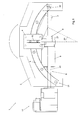
- the X-ray diffractometer of the invention comprises a supporting structure 2 in which it is possible to identify a curved guide 3 in the shape of an arc of a circle, along which a supporting carriage 4 is slidingly constrained.
- the supporting carriage 4 is coupled with the curved guide 3 by means of a system of recirculating balls.
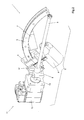
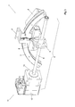
- the X-ray diffractometer 1 also comprises a driving unit, indicated by 5 in Figures from 2 to 4, which allows the movement of the above mentioned supporting carriage 4 along the curved guide 3 .
- the supporting carriage 4 is suited to support in a stable manner a source unit 6 of X-rays and a detector unit 7 of the same X-rays diffracted by the sample subjected to analysis.
- the above mentioned two units 6 and 7 are suited to move along the curved guide 3, as indicated by the arrow in Figure 1 , with respect to the point at the height of which the sample to be analysed is arranged.
- the source unit 6 and the detector unit 7 are mutually arranged on said supporting carriage 4 so that the incident beam and the diffracted beam form an angle 2 ⁇ , indicated in Figure 1 , that depends on the type of material used.
- the source unit 6 and the detector unit 7 move together along the curved guide 3 and around the sample in order to allow the latter to be observed from various angles.
- the X-ray diffractometer 1 is provided with two supporting carriages 4 , each one of which supports one of the two source 6 and detector 7 units with the possibility to move independently along the above mentioned curved guide 3 over a limited and predetermined length.
- a first supporting carriage may move over half of the extension of the curved guide 3 and the other supporting carriage may move over the remaining half.
- the X-ray diffractometer 1 of the invention would be capable of performing other types of diffractometric analyses in addition to the measurement of the residual stresses.
- the above mentioned driving unit 5 comprises a driving bar 8 , of the linear type, which is essentially arranged between the opposite ends 31 and 32 of a chord of the curved guide 3 , as shown in Figure 1 .
- This position of the driving bar 8 with respect to the curved guide 3 is permanent.
- said driving bar 8 defines a longitudinal axis x that lies on a plane ⁇ essentially parallel to the plane p defined by the same curved guide 3 .
- a drive element 9 that can move essentially along the entire extension of the driving bar 8 is slidingly constrained to said driving bar 8 .
- said drive element 9 is operatively associated with the supporting carriage 4 through articulation means 10 , so as to allow the linear motion of the same drive element 9 to be transformed into the curved motion of the supporting carriage 4 determined by the curved guide 3.
- a first end of the same driving bar 8 is associated with power means 11 that in the preferred embodiment of the invention comprise an electric motor 12 and a rotary shaft 13 coaxially connected to the driving bar 8 , as indicated in Figure 2 .
- articulation means 10 include rotation-translation means for the translation and simultaneous rotation of the supporting carriage 4 with respect to the drive element 9 .
- Said rotation movement associated with the translation movement allows said supporting carriage 4 to move along the curved guide 3 when the drive element 9 is set moving along the longitudinal axis x of the driving bar 8 through said power means 11.
- said rotation-translation means include slide means 14 comprising a linear guide 15 operatively associated with a slit 16.
- Said slide means 14 are components generally available on the market, therefore using them makes it possible to achieve one of the objects of the present invention consisting, in fact, in the construction of an X-ray diffractometer essentially made up of components available on the market.
- said rotation-translation means may comprise other elements different from the slide means 14 , provided that they allow the translation and simultaneous rotation of the supporting carriage 4 with respect to the drive element 9 .
- Figures from 2 to 4 show three possible arrangements of the supporting carriage 4 along the curved guide 3 and the corresponding three positions of the drive element 9 along the driving bar 8 , which can be obtained thanks to the presence of the above mentioned rotation-translation means.
- the linear guide 15 projects from the supporting carriage 4 and the corresponding slit 16 is defined in the drive element 9.
- the slit 16 is created in a section element 17 rotatingly associated with the above mentioned drive element 9 through a pin 18 and a bearing 19 incorporated in the section element itself.
- Said composition allows the slit 16 to rotate with respect to the drive element 9 with which it is coupled, so as to follow the orientation that the supporting carriage 4 assumes during its movement along the curved guide 3 , as can be seen in Figures 2 and 4 .
- the slit 16 can be made directly in the drive element 9 and instead of the linear guide 15 it is possible to provide a pin rotatingly associated with the supporting carriage 4 , so as to allow the rotation of the same supporting carriage 4 with respect to the drive element 9 at the same time as the linear translation of the pin inside the slit 16 and thus, consequently, the linear translation between the supporting carriage 4 and the drive element 9 .
- linear guide 15 may project from the drive element 9 and the slit 16 may be defined in the supporting carriage 4, provided that said configuration allows the rotation together with the mutual translation of the two elements 4 and 9 considered above.
- the driving bar 8 As shown in Figure 2 , according to the preferred embodiment of the invention it is a screw 20 and the drive element 9 is the relative nut screw 21.
- the coupling of the screw 20 and the nut screw 21 is made possible through a system with recirculating balls.
- the driving bar 8 and the drive element 9 may be configured in a different manner, provided that the latter can slide along the driving bar 8.
- the driving unit 5 should include two driving bars arranged along to distinct chords of the same curved guide 3.
- the two driving bars 8 can be arranged on the same side with respect to the curved guide 3 , or alternatively they can be arranged on opposite sides of the same curved guide 3.
- each driving bar 8 would be operatively coupled with a drive element 9 , in turn associated with one of the two supporting carriages 4 through the above mentioned articulation means 10 , so as to allow the independent movement of the former along the curved guide 3 , as explained with reference to the preferred embodiment of the invention described above.
- the X-ray source unit 6 and the detector unit 7 would have the possibility to move around the sample at different speeds and with different angles of incidence.
- the X-ray diffractometer 1 of the invention also comprises precision adjustment means, not represented in the figures, that make it possible to position the same X-ray diffractometer 1 precisely with respect to the sample to be analysed.
- said adjustment means comprise a laser pointer aligned with the X-ray source unit 6, so that it is possible to visually verify the incidence point of the X-rays on the sample to be analysed.
- the precision adjustment means comprise a micrometer.
- the precision adjustment means also comprise a spirit level 360°, with which it is possible to verify the inclination of the X-ray diffractometer 1 with respect to the sample to be analysed in the different directions.
- precision adjustment means comprise other precision elements, provided that these allow the diffractometer to be positioned precisely with respect to the sample and provided that they belong to the known art.
- the technician in charge with the determination of the residual stress in a sample subjected to analysis which cannot be removed from its normal operating position transports the X-ray diffractometer 1 of the invention to the site and arranges it in proximity to the point where the analysis has to be performed, fixing it stably through suitable coupling means, like hydraulic arms or magnetic means.
- the technician precisely defines the position of the X-ray diffractometer 1 with respect to the point to be analysed.
- the technician using said precision adjustment means 22 , precisely centers the point of incidence of the X-rays with respect to the sample to be analysed.
- the technician can start analysing the sample, activating the X-ray diffractometer 1 of the invention, whose operating modes have been described above respectively for the first and second embodiment.
- the diffractometer that is the subject of the invention achieves all the set objects.
- the invention achieves the object to provide a portable diffractometer whose size and overall dimensions are reduced compared to the diffractometers of the known art, so that they can be used for on-site applications even in conditions of limited space.
- a further object achieved by the invention is to provide a portable X-ray diffractometer ensuring higher precision and repeatability of the movements of the various components compared to the diffractometers of the known art. Consequently, the invention also achieves the object to provide an X-ray diffractometer that makes it possible to obtain measurements that are much more precise and constant compared to those obtained with the diffractometers of the known art.
- the invention also achieves the object to provide an X-ray diffractometer essentially comprising components normally available and easy to find on the market, so as to reduce its costs.
- the X-ray diffractometer that is the subject of the invention may undergo changes that, though not illustrated or described herein, shall nonetheless be covered by the present patent, provided that they come within the scope of the claims that follow.
Landscapes
- Chemical & Material Sciences (AREA)
- Crystallography & Structural Chemistry (AREA)
- Physics & Mathematics (AREA)
- Health & Medical Sciences (AREA)
- Life Sciences & Earth Sciences (AREA)
- Analytical Chemistry (AREA)
- Biochemistry (AREA)
- General Health & Medical Sciences (AREA)
- General Physics & Mathematics (AREA)
- Immunology (AREA)
- Pathology (AREA)
- Analysing Materials By The Use Of Radiation (AREA)
Applications Claiming Priority (1)
| Application Number | Priority Date | Filing Date | Title |
|---|---|---|---|
| ITVI2010A000351A IT1403478B1 (it) | 2010-12-28 | 2010-12-28 | Diffrattometro a raggi x del tipo portatile perfezionato |
Publications (2)
| Publication Number | Publication Date |
|---|---|
| EP2472252A1 true EP2472252A1 (de) | 2012-07-04 |
| EP2472252B1 EP2472252B1 (de) | 2013-11-20 |
Family
ID=43737559
Family Applications (1)
| Application Number | Title | Priority Date | Filing Date |
|---|---|---|---|
| EP11195865.8A Active EP2472252B1 (de) | 2010-12-28 | 2011-12-28 | Portables Röntgendiffraktometer |
Country Status (2)
| Country | Link |
|---|---|
| EP (1) | EP2472252B1 (de) |
| IT (1) | IT1403478B1 (de) |
Cited By (2)
| Publication number | Priority date | Publication date | Assignee | Title |
|---|---|---|---|---|
| EP2778666A3 (de) * | 2013-03-15 | 2014-12-03 | Proto Manufacturing Ltd. | Röntgenstrahldiffraktionsvorrichtung und -verfahren |
| JP5954642B1 (ja) * | 2015-03-20 | 2016-07-20 | パルステック工業株式会社 | X線回折測定装置および3軸残留応力測定の必要性判定方法 |
Citations (5)
| Publication number | Priority date | Publication date | Assignee | Title |
|---|---|---|---|---|
| US3728541A (en) * | 1969-05-20 | 1973-04-17 | Yale Res And Dev Co Ltd | X-ray diffractometer |
| DE2633114B1 (de) * | 1976-07-23 | 1977-12-08 | Allianz Zentrum Fuer Technik G | Spannungsmessgoniometer fuer die bauteilpruefung |
| US4071758A (en) * | 1975-08-04 | 1978-01-31 | Max-Planck-Gesellschaft Zur Forderung Der Wissenschafter E.V. | Multiple test X-ray goniometer |
| JPH06313757A (ja) * | 1993-02-19 | 1994-11-08 | Rigaku Corp | Exafs測定装置 |
| EP2112505A1 (de) * | 2008-04-22 | 2009-10-28 | Bruker AXS GmbH | Röntgendiffraktometer zum mechanisch korrelierten Verfahren von Quelle, Detektor und Probenposition |
-
2010
- 2010-12-28 IT ITVI2010A000351A patent/IT1403478B1/it active
-
2011
- 2011-12-28 EP EP11195865.8A patent/EP2472252B1/de active Active
Patent Citations (5)
| Publication number | Priority date | Publication date | Assignee | Title |
|---|---|---|---|---|
| US3728541A (en) * | 1969-05-20 | 1973-04-17 | Yale Res And Dev Co Ltd | X-ray diffractometer |
| US4071758A (en) * | 1975-08-04 | 1978-01-31 | Max-Planck-Gesellschaft Zur Forderung Der Wissenschafter E.V. | Multiple test X-ray goniometer |
| DE2633114B1 (de) * | 1976-07-23 | 1977-12-08 | Allianz Zentrum Fuer Technik G | Spannungsmessgoniometer fuer die bauteilpruefung |
| JPH06313757A (ja) * | 1993-02-19 | 1994-11-08 | Rigaku Corp | Exafs測定装置 |
| EP2112505A1 (de) * | 2008-04-22 | 2009-10-28 | Bruker AXS GmbH | Röntgendiffraktometer zum mechanisch korrelierten Verfahren von Quelle, Detektor und Probenposition |
Cited By (3)
| Publication number | Priority date | Publication date | Assignee | Title |
|---|---|---|---|---|
| EP2778666A3 (de) * | 2013-03-15 | 2014-12-03 | Proto Manufacturing Ltd. | Röntgenstrahldiffraktionsvorrichtung und -verfahren |
| US9613728B2 (en) | 2013-03-15 | 2017-04-04 | Proto Manufacturing Ltd. | X-ray diffraction apparatus and method |
| JP5954642B1 (ja) * | 2015-03-20 | 2016-07-20 | パルステック工業株式会社 | X線回折測定装置および3軸残留応力測定の必要性判定方法 |
Also Published As
| Publication number | Publication date |
|---|---|
| IT1403478B1 (it) | 2013-10-17 |
| ITVI20100351A1 (it) | 2012-06-29 |
| EP2472252B1 (de) | 2013-11-20 |
Similar Documents
| Publication | Publication Date | Title |
|---|---|---|
| CN204495749U (zh) | 连续衍射分光与探测装置及顺序式x射线荧光光谱仪 | |
| CN1534289B (zh) | X射线衍射装置 | |
| US7075296B2 (en) | Inspection carriage for turbine blades | |
| KR100990592B1 (ko) | 회절 분석기 및 회절 분석 방법 | |
| EP1621873B1 (de) | Screeningsystem mittels eines zwischen einem Transmissions- und Reflektionsmodus konvertierbaren Röntgendiffraktometer | |
| JPS632470B2 (de) | ||
| EP2472252B1 (de) | Portables Röntgendiffraktometer | |
| US20140026727A1 (en) | Microtome having a piezoelectric linear actuator | |
| JP6322628B2 (ja) | 1d及び2dビームを提供するx線ビームシステム | |
| CN101968442A (zh) | 一种傅里叶变换光谱仪用曲柄滑块动镜扫描系统 | |
| CN110907484A (zh) | 一种三维共聚焦的微束x射线应力仪 | |
| JP3245475B2 (ja) | Exafs測定装置 | |
| EP1995583B1 (de) | Materialteilabnehmvorrichtung | |
| RU2374616C1 (ru) | Центробежная установка для испытания материалов | |
| CN119618064A (zh) | 一种齿轮加工用精度检测装置 | |
| JP4619282B2 (ja) | エックス線分析装置 | |
| JP2006201167A (ja) | 位置決め装置 | |
| CN105891246A (zh) | 一种x射线荧光探测装置 | |
| CN201034952Y (zh) | 一种复合位移式连读分析RoHS指令痕量元素的检测分析仪 | |
| JP2951687B2 (ja) | エキザフス装置 | |
| JP7485872B2 (ja) | 放射線測定装置 | |
| CN216525442U (zh) | 一种模块集成的柔性材料拉伸过程中原位光谱测试试验机 | |
| JPS60122362A (ja) | X−線検査装置 | |
| CN222144910U (zh) | 一种围绕罗兰圆角度转动装置 | |
| CN219657413U (zh) | 一种用于表面应力检测的校准装置 |
Legal Events
| Date | Code | Title | Description |
|---|---|---|---|
| AK | Designated contracting states |
Kind code of ref document: A1 Designated state(s): AL AT BE BG CH CY CZ DE DK EE ES FI FR GB GR HR HU IE IS IT LI LT LU LV MC MK MT NL NO PL PT RO RS SE SI SK SM TR |
|
| AX | Request for extension of the european patent |
Extension state: BA ME |
|
| PUAI | Public reference made under article 153(3) epc to a published international application that has entered the european phase |
Free format text: ORIGINAL CODE: 0009012 |
|
| 17P | Request for examination filed |
Effective date: 20130103 |
|
| RIC1 | Information provided on ipc code assigned before grant |
Ipc: G01N 23/20 20060101AFI20130218BHEP |
|
| GRAP | Despatch of communication of intention to grant a patent |
Free format text: ORIGINAL CODE: EPIDOSNIGR1 |
|
| INTG | Intention to grant announced |
Effective date: 20130415 |
|
| RIN1 | Information on inventor provided before grant (corrected) |
Inventor name: DEFLORIAN, CORRADO Inventor name: MARCONI, GIAN PAOLO |
|
| GRAP | Despatch of communication of intention to grant a patent |
Free format text: ORIGINAL CODE: EPIDOSNIGR1 |
|
| GRAS | Grant fee paid |
Free format text: ORIGINAL CODE: EPIDOSNIGR3 |
|
| INTG | Intention to grant announced |
Effective date: 20130919 |
|
| GRAA | (expected) grant |
Free format text: ORIGINAL CODE: 0009210 |
|
| RIN1 | Information on inventor provided before grant (corrected) |
Inventor name: MARCONI, GIAN PAOLO Inventor name: DEFLORIAN, CORRADO |
|
| AK | Designated contracting states |
Kind code of ref document: B1 Designated state(s): AL AT BE BG CH CY CZ DE DK EE ES FI FR GB GR HR HU IE IS IT LI LT LU LV MC MK MT NL NO PL PT RO RS SE SI SK SM TR |
|
| REG | Reference to a national code |
Ref country code: GB Ref legal event code: FG4D |
|
| REG | Reference to a national code |
Ref country code: CH Ref legal event code: EP |
|
| REG | Reference to a national code |
Ref country code: AT Ref legal event code: REF Ref document number: 641923 Country of ref document: AT Kind code of ref document: T Effective date: 20131215 |
|
| REG | Reference to a national code |
Ref country code: IE Ref legal event code: FG4D |
|
| REG | Reference to a national code |
Ref country code: DE Ref legal event code: R096 Ref document number: 602011003854 Country of ref document: DE Effective date: 20140116 |
|
| REG | Reference to a national code |
Ref country code: NL Ref legal event code: VDEP Effective date: 20131120 |
|
| REG | Reference to a national code |
Ref country code: AT Ref legal event code: MK05 Ref document number: 641923 Country of ref document: AT Kind code of ref document: T Effective date: 20131120 |
|
| REG | Reference to a national code |
Ref country code: LT Ref legal event code: MG4D |
|
| PG25 | Lapsed in a contracting state [announced via postgrant information from national office to epo] |
Ref country code: NL Free format text: LAPSE BECAUSE OF FAILURE TO SUBMIT A TRANSLATION OF THE DESCRIPTION OR TO PAY THE FEE WITHIN THE PRESCRIBED TIME-LIMIT Effective date: 20131120 Ref country code: HR Free format text: LAPSE BECAUSE OF FAILURE TO SUBMIT A TRANSLATION OF THE DESCRIPTION OR TO PAY THE FEE WITHIN THE PRESCRIBED TIME-LIMIT Effective date: 20131120 Ref country code: IS Free format text: LAPSE BECAUSE OF FAILURE TO SUBMIT A TRANSLATION OF THE DESCRIPTION OR TO PAY THE FEE WITHIN THE PRESCRIBED TIME-LIMIT Effective date: 20140320 Ref country code: SE Free format text: LAPSE BECAUSE OF FAILURE TO SUBMIT A TRANSLATION OF THE DESCRIPTION OR TO PAY THE FEE WITHIN THE PRESCRIBED TIME-LIMIT Effective date: 20131120 Ref country code: FI Free format text: LAPSE BECAUSE OF FAILURE TO SUBMIT A TRANSLATION OF THE DESCRIPTION OR TO PAY THE FEE WITHIN THE PRESCRIBED TIME-LIMIT Effective date: 20131120 Ref country code: NO Free format text: LAPSE BECAUSE OF FAILURE TO SUBMIT A TRANSLATION OF THE DESCRIPTION OR TO PAY THE FEE WITHIN THE PRESCRIBED TIME-LIMIT Effective date: 20140220 Ref country code: LT Free format text: LAPSE BECAUSE OF FAILURE TO SUBMIT A TRANSLATION OF THE DESCRIPTION OR TO PAY THE FEE WITHIN THE PRESCRIBED TIME-LIMIT Effective date: 20131120 |
|
| PG25 | Lapsed in a contracting state [announced via postgrant information from national office to epo] |
Ref country code: LV Free format text: LAPSE BECAUSE OF FAILURE TO SUBMIT A TRANSLATION OF THE DESCRIPTION OR TO PAY THE FEE WITHIN THE PRESCRIBED TIME-LIMIT Effective date: 20131120 Ref country code: RS Free format text: LAPSE BECAUSE OF FAILURE TO SUBMIT A TRANSLATION OF THE DESCRIPTION OR TO PAY THE FEE WITHIN THE PRESCRIBED TIME-LIMIT Effective date: 20131120 Ref country code: BE Free format text: LAPSE BECAUSE OF FAILURE TO SUBMIT A TRANSLATION OF THE DESCRIPTION OR TO PAY THE FEE WITHIN THE PRESCRIBED TIME-LIMIT Effective date: 20131120 Ref country code: AT Free format text: LAPSE BECAUSE OF FAILURE TO SUBMIT A TRANSLATION OF THE DESCRIPTION OR TO PAY THE FEE WITHIN THE PRESCRIBED TIME-LIMIT Effective date: 20131120 Ref country code: ES Free format text: LAPSE BECAUSE OF FAILURE TO SUBMIT A TRANSLATION OF THE DESCRIPTION OR TO PAY THE FEE WITHIN THE PRESCRIBED TIME-LIMIT Effective date: 20131120 |
|
| PG25 | Lapsed in a contracting state [announced via postgrant information from national office to epo] |
Ref country code: PT Free format text: LAPSE BECAUSE OF FAILURE TO SUBMIT A TRANSLATION OF THE DESCRIPTION OR TO PAY THE FEE WITHIN THE PRESCRIBED TIME-LIMIT Effective date: 20140320 |
|
| PG25 | Lapsed in a contracting state [announced via postgrant information from national office to epo] |
Ref country code: EE Free format text: LAPSE BECAUSE OF FAILURE TO SUBMIT A TRANSLATION OF THE DESCRIPTION OR TO PAY THE FEE WITHIN THE PRESCRIBED TIME-LIMIT Effective date: 20131120 |
|
| REG | Reference to a national code |
Ref country code: DE Ref legal event code: R097 Ref document number: 602011003854 Country of ref document: DE |
|
| PG25 | Lapsed in a contracting state [announced via postgrant information from national office to epo] |
Ref country code: RO Free format text: LAPSE BECAUSE OF FAILURE TO SUBMIT A TRANSLATION OF THE DESCRIPTION OR TO PAY THE FEE WITHIN THE PRESCRIBED TIME-LIMIT Effective date: 20131120 Ref country code: CZ Free format text: LAPSE BECAUSE OF FAILURE TO SUBMIT A TRANSLATION OF THE DESCRIPTION OR TO PAY THE FEE WITHIN THE PRESCRIBED TIME-LIMIT Effective date: 20131120 Ref country code: PL Free format text: LAPSE BECAUSE OF FAILURE TO SUBMIT A TRANSLATION OF THE DESCRIPTION OR TO PAY THE FEE WITHIN THE PRESCRIBED TIME-LIMIT Effective date: 20131120 Ref country code: SK Free format text: LAPSE BECAUSE OF FAILURE TO SUBMIT A TRANSLATION OF THE DESCRIPTION OR TO PAY THE FEE WITHIN THE PRESCRIBED TIME-LIMIT Effective date: 20131120 |
|
| REG | Reference to a national code |
Ref country code: IE Ref legal event code: MM4A |
|
| PLBE | No opposition filed within time limit |
Free format text: ORIGINAL CODE: 0009261 |
|
| STAA | Information on the status of an ep patent application or granted ep patent |
Free format text: STATUS: NO OPPOSITION FILED WITHIN TIME LIMIT |
|
| PG25 | Lapsed in a contracting state [announced via postgrant information from national office to epo] |
Ref country code: DK Free format text: LAPSE BECAUSE OF FAILURE TO SUBMIT A TRANSLATION OF THE DESCRIPTION OR TO PAY THE FEE WITHIN THE PRESCRIBED TIME-LIMIT Effective date: 20131120 |
|
| 26N | No opposition filed |
Effective date: 20140821 |
|
| PG25 | Lapsed in a contracting state [announced via postgrant information from national office to epo] |
Ref country code: IE Free format text: LAPSE BECAUSE OF NON-PAYMENT OF DUE FEES Effective date: 20131228 |
|
| REG | Reference to a national code |
Ref country code: DE Ref legal event code: R097 Ref document number: 602011003854 Country of ref document: DE Effective date: 20140821 |
|
| PG25 | Lapsed in a contracting state [announced via postgrant information from national office to epo] |
Ref country code: SI Free format text: LAPSE BECAUSE OF FAILURE TO SUBMIT A TRANSLATION OF THE DESCRIPTION OR TO PAY THE FEE WITHIN THE PRESCRIBED TIME-LIMIT Effective date: 20131120 |
|
| PG25 | Lapsed in a contracting state [announced via postgrant information from national office to epo] |
Ref country code: MC Free format text: LAPSE BECAUSE OF FAILURE TO SUBMIT A TRANSLATION OF THE DESCRIPTION OR TO PAY THE FEE WITHIN THE PRESCRIBED TIME-LIMIT Effective date: 20131120 |
|
| PG25 | Lapsed in a contracting state [announced via postgrant information from national office to epo] |
Ref country code: CY Free format text: LAPSE BECAUSE OF FAILURE TO SUBMIT A TRANSLATION OF THE DESCRIPTION OR TO PAY THE FEE WITHIN THE PRESCRIBED TIME-LIMIT Effective date: 20131120 Ref country code: SM Free format text: LAPSE BECAUSE OF FAILURE TO SUBMIT A TRANSLATION OF THE DESCRIPTION OR TO PAY THE FEE WITHIN THE PRESCRIBED TIME-LIMIT Effective date: 20131120 |
|
| PG25 | Lapsed in a contracting state [announced via postgrant information from national office to epo] |
Ref country code: LU Free format text: LAPSE BECAUSE OF NON-PAYMENT OF DUE FEES Effective date: 20131228 Ref country code: MK Free format text: LAPSE BECAUSE OF FAILURE TO SUBMIT A TRANSLATION OF THE DESCRIPTION OR TO PAY THE FEE WITHIN THE PRESCRIBED TIME-LIMIT Effective date: 20131120 Ref country code: HU Free format text: LAPSE BECAUSE OF FAILURE TO SUBMIT A TRANSLATION OF THE DESCRIPTION OR TO PAY THE FEE WITHIN THE PRESCRIBED TIME-LIMIT; INVALID AB INITIO Effective date: 20111228 Ref country code: BG Free format text: LAPSE BECAUSE OF FAILURE TO SUBMIT A TRANSLATION OF THE DESCRIPTION OR TO PAY THE FEE WITHIN THE PRESCRIBED TIME-LIMIT Effective date: 20131120 |
|
| REG | Reference to a national code |
Ref country code: CH Ref legal event code: PL |
|
| PG25 | Lapsed in a contracting state [announced via postgrant information from national office to epo] |
Ref country code: MT Free format text: LAPSE BECAUSE OF FAILURE TO SUBMIT A TRANSLATION OF THE DESCRIPTION OR TO PAY THE FEE WITHIN THE PRESCRIBED TIME-LIMIT Effective date: 20131120 Ref country code: GR Free format text: LAPSE BECAUSE OF NON-PAYMENT OF DUE FEES Effective date: 20131120 |
|
| PG25 | Lapsed in a contracting state [announced via postgrant information from national office to epo] |
Ref country code: LI Free format text: LAPSE BECAUSE OF NON-PAYMENT OF DUE FEES Effective date: 20141231 Ref country code: CH Free format text: LAPSE BECAUSE OF NON-PAYMENT OF DUE FEES Effective date: 20141231 |
|
| REG | Reference to a national code |
Ref country code: FR Ref legal event code: PLFP Year of fee payment: 5 |
|
| PG25 | Lapsed in a contracting state [announced via postgrant information from national office to epo] |
Ref country code: GR Free format text: LAPSE BECAUSE OF FAILURE TO SUBMIT A TRANSLATION OF THE DESCRIPTION OR TO PAY THE FEE WITHIN THE PRESCRIBED TIME-LIMIT Effective date: 20140221 |
|
| PG25 | Lapsed in a contracting state [announced via postgrant information from national office to epo] |
Ref country code: TR Free format text: LAPSE BECAUSE OF FAILURE TO SUBMIT A TRANSLATION OF THE DESCRIPTION OR TO PAY THE FEE WITHIN THE PRESCRIBED TIME-LIMIT Effective date: 20131120 |
|
| GBPC | Gb: european patent ceased through non-payment of renewal fee |
Effective date: 20151228 |
|
| PG25 | Lapsed in a contracting state [announced via postgrant information from national office to epo] |
Ref country code: GB Free format text: LAPSE BECAUSE OF NON-PAYMENT OF DUE FEES Effective date: 20151228 |
|
| REG | Reference to a national code |
Ref country code: FR Ref legal event code: PLFP Year of fee payment: 6 |
|
| REG | Reference to a national code |
Ref country code: DE Ref legal event code: R082 Ref document number: 602011003854 Country of ref document: DE Representative=s name: KUHNEN & WACKER PATENT- UND RECHTSANWALTSBUERO, DE Ref country code: DE Ref legal event code: R082 Ref document number: 602011003854 Country of ref document: DE Representative=s name: GUSTORF, GERHARD, DIPL.-ING., DE Ref country code: DE Ref legal event code: R081 Ref document number: 602011003854 Country of ref document: DE Owner name: TNX S.R.L., IT Free format text: FORMER OWNERS: FONDAZIONE BRUNO KESSLER, TRENTO, IT; TNX S.R.L., TRENTO, IT Ref country code: DE Ref legal event code: R081 Ref document number: 602011003854 Country of ref document: DE Owner name: TNX S.R.L. IN LIQUIDAZIONE, IT Free format text: FORMER OWNERS: FONDAZIONE BRUNO KESSLER, TRENTO, IT; TNX S.R.L., TRENTO, IT Ref country code: DE Ref legal event code: R081 Ref document number: 602011003854 Country of ref document: DE Owner name: 2 EFFE ENGINEERING S.R.L., IT Free format text: FORMER OWNERS: FONDAZIONE BRUNO KESSLER, TRENTO, IT; TNX S.R.L., TRENTO, IT |
|
| REG | Reference to a national code |
Ref country code: FR Ref legal event code: PLFP Year of fee payment: 7 |
|
| REG | Reference to a national code |
Ref country code: FR Ref legal event code: TP Owner name: TNX S.R.L., IT Effective date: 20180214 |
|
| REG | Reference to a national code |
Ref country code: DE Ref legal event code: R082 Ref document number: 602011003854 Country of ref document: DE Representative=s name: KUHNEN & WACKER PATENT- UND RECHTSANWALTSBUERO, DE Ref country code: DE Ref legal event code: R082 Ref document number: 602011003854 Country of ref document: DE Representative=s name: GUSTORF, GERHARD, DIPL.-ING., DE Ref country code: DE Ref legal event code: R081 Ref document number: 602011003854 Country of ref document: DE Owner name: TNX S.R.L. IN LIQUIDAZIONE, IT Free format text: FORMER OWNER: TNX S.R.L., TRENTO, IT Ref country code: DE Ref legal event code: R081 Ref document number: 602011003854 Country of ref document: DE Owner name: 2 EFFE ENGINEERING S.R.L., IT Free format text: FORMER OWNER: TNX S.R.L., TRENTO, IT |
|
| REG | Reference to a national code |
Ref country code: DE Ref legal event code: R082 Ref document number: 602011003854 Country of ref document: DE Representative=s name: KUHNEN & WACKER PATENT- UND RECHTSANWALTSBUERO, DE Ref country code: DE Ref legal event code: R082 Ref document number: 602011003854 Country of ref document: DE Representative=s name: GUSTORF, GERHARD, DIPL.-ING., DE Ref country code: DE Ref legal event code: R081 Ref document number: 602011003854 Country of ref document: DE Owner name: 2 EFFE ENGINEERING S.R.L., IT Free format text: FORMER OWNER: TNX S.R.L. IN LIQUIDAZIONE, AGNOSINE, IT |
|
| PG25 | Lapsed in a contracting state [announced via postgrant information from national office to epo] |
Ref country code: AL Free format text: LAPSE BECAUSE OF FAILURE TO SUBMIT A TRANSLATION OF THE DESCRIPTION OR TO PAY THE FEE WITHIN THE PRESCRIBED TIME-LIMIT Effective date: 20131120 |
|
| REG | Reference to a national code |
Ref country code: FR Ref legal event code: CA Effective date: 20181106 Ref country code: FR Ref legal event code: CD Owner name: 2 EFFE ENGINEERING SRL, IT Effective date: 20181106 Ref country code: FR Ref legal event code: TP Owner name: 2 EFFE ENGINEERING SRL, IT Effective date: 20181106 |
|
| REG | Reference to a national code |
Ref country code: DE Ref legal event code: R082 Ref document number: 602011003854 Country of ref document: DE Representative=s name: KUHNEN & WACKER PATENT- UND RECHTSANWALTSBUERO, DE |
|
| P01 | Opt-out of the competence of the unified patent court (upc) registered |
Effective date: 20230530 |
|
| PGFP | Annual fee paid to national office [announced via postgrant information from national office to epo] |
Ref country code: IT Payment date: 20250925 Year of fee payment: 15 |
|
| PGFP | Annual fee paid to national office [announced via postgrant information from national office to epo] |
Ref country code: DE Payment date: 20251211 Year of fee payment: 15 |
|
| PGFP | Annual fee paid to national office [announced via postgrant information from national office to epo] |
Ref country code: FR Payment date: 20251222 Year of fee payment: 15 |