EP2472368B1 - Eingabevorrichtung - Google Patents
Eingabevorrichtung Download PDFInfo
- Publication number
- EP2472368B1 EP2472368B1 EP10811516.3A EP10811516A EP2472368B1 EP 2472368 B1 EP2472368 B1 EP 2472368B1 EP 10811516 A EP10811516 A EP 10811516A EP 2472368 B1 EP2472368 B1 EP 2472368B1
- Authority
- EP
- European Patent Office
- Prior art keywords
- piezoelectric element
- touch
- drive
- load
- touch sensor
- Prior art date
- Legal status (The legal status is an assumption and is not a legal conclusion. Google has not performed a legal analysis and makes no representation as to the accuracy of the status listed.)
- Active
Links
Images


Classifications
-
- G—PHYSICS
- G06—COMPUTING OR CALCULATING; COUNTING
- G06F—ELECTRIC DIGITAL DATA PROCESSING
- G06F3/00—Input arrangements for transferring data to be processed into a form capable of being handled by the computer; Output arrangements for transferring data from processing unit to output unit, e.g. interface arrangements
- G06F3/01—Input arrangements or combined input and output arrangements for interaction between user and computer
- G06F3/016—Input arrangements with force or tactile feedback as computer generated output to the user
-
- G—PHYSICS
- G06—COMPUTING OR CALCULATING; COUNTING
- G06F—ELECTRIC DIGITAL DATA PROCESSING
- G06F3/00—Input arrangements for transferring data to be processed into a form capable of being handled by the computer; Output arrangements for transferring data from processing unit to output unit, e.g. interface arrangements
- G06F3/01—Input arrangements or combined input and output arrangements for interaction between user and computer
- G06F3/03—Arrangements for converting the position or the displacement of a member into a coded form
- G06F3/041—Digitisers, e.g. for touch screens or touch pads, characterised by the transducing means
- G06F3/0414—Digitisers, e.g. for touch screens or touch pads, characterised by the transducing means using force sensing means to determine a position
- G06F3/04142—Digitisers, e.g. for touch screens or touch pads, characterised by the transducing means using force sensing means to determine a position the force sensing means being located peripherally, e.g. disposed at the corners or at the side of a touch sensing plate
-
- G—PHYSICS
- G06—COMPUTING OR CALCULATING; COUNTING
- G06F—ELECTRIC DIGITAL DATA PROCESSING
- G06F3/00—Input arrangements for transferring data to be processed into a form capable of being handled by the computer; Output arrangements for transferring data from processing unit to output unit, e.g. interface arrangements
- G06F3/01—Input arrangements or combined input and output arrangements for interaction between user and computer
- G06F3/03—Arrangements for converting the position or the displacement of a member into a coded form
- G06F3/041—Digitisers, e.g. for touch screens or touch pads, characterised by the transducing means
- G06F3/0416—Control or interface arrangements specially adapted for digitisers
-
- G—PHYSICS
- G06—COMPUTING OR CALCULATING; COUNTING
- G06F—ELECTRIC DIGITAL DATA PROCESSING
- G06F2203/00—Indexing scheme relating to G06F3/00 - G06F3/048
- G06F2203/041—Indexing scheme relating to G06F3/041 - G06F3/045
- G06F2203/04105—Pressure sensors for measuring the pressure or force exerted on the touch surface without providing the touch position
Definitions
- the present invention relates to an input apparatus having a touch sensor.
- input apparatus such as operation units, switches and the like having touch sensors such as touch panels, touch switches and the like to receive input operations by users have been widely used for mobile terminals such as mobile phones, information equipment such as calculators and ticket vending machines, home electric appliances such as microwaves, TV sets and lighting equipment, industrial equipment (FA equipment) and the like.
- touch sensors such as a resistive film type, a capacitive type, an optical type and the like.
- touch sensors of these types receive a touch input by a finger or a stylus pen and, unlike push-button switches, the touch sensors themselves are not physically displaced even when being touched.
- Document JP 11212725 A discloses a touch screen with piezoelectric elements that perform the dual fucntions of detecting a pressure load and generating a tactile sensation.
- Document JP 63130357 A discloses a discharge circuit for discharging a residual electric charge in a piezoelectric element.
- the threshold for the touch sensor to receive a touch input is a threshold at which the touch sensor responds, which is, for a touch sensor of the resistive film type, a threshold of a pressure at which an upper conductive film is contacted to a lower conductive film and, for a touch sensor of the capacitive type, a threshold for detection of an electric signal by contact.
- the applicant has developed an input apparatus which detects a pressure load on a touch face of the touch sensor and, when the pressure load detected reaches a predetermined standard to provide the tactile sensation, vibrates the touch face.
- This input apparatus when the load detected satisfies the predetermined standard to provide the tactile sensation, provides a pressing object such as a finger with a click sensation obtained when depressing a push-button switch such as a metal dome in pressing such the metal dome switch.
- the tactile sensation is provided when the operator pushes the touch face and the pressure load of the push reaches the predetermined standard. As a result, it is possible to allow the operator to perceive reception of an input while reliably preventing erroneous operations triggered by an unintentional touch described above and the feeling of strangeness.
- a load sensor to detect the pressure load on the touch sensor and an actuator to vibrate the touch sensor are used in addition to basic components such as the touch sensor and a control unit.
- basic components such as the touch sensor and a control unit.
- the applicant has developed an apparatus which utilizes direct piezoelectric effect and converse piezoelectric effect of a piezoelectric element serving as the load sensor to detect the pressure load on the touch face of the touch sensor and the actuator to vibrate the touch face such that the tactile sensation is provided to the pressing object.
- the applicant found out that, in using the piezoelectric element for as the load sensor and as the actuator, there is a need for an improvement as follows.
- the piezoelectric element is connected to a piezoelectric control circuit, which detects the pressure load based on an output voltage of the piezoelectric element and then supplies a drive signal to the piezoelectric element to vibrate the piezoelectric element when the pressure load satisfies the predetermined standard to provide the tactile sensation.
- a required drive signal Vd is applied to the piezoelectric element in order to drive the piezoelectric element.
- the drive signal Vd a sine wave with a predetermined frequency for one period is applied.
- the piezoelectric element is vibrated under the load, that is, while the touch sensor is pressed by the pressing object. Accordingly, the drive signal Vd to vibrate the piezoelectric element is larger than the output voltage Vs generated when pressed by the pressing object and, for example, 30 V p-p . Moreover, in a state that the output voltage Vs of the piezoelectric element is at the standard voltage Vref, the drive signal Vd is applied superimposing the output voltage Vs (standard voltage Vref). Therefore, it may exceed a range of a working voltage of some piezoelectric elements, resulting in limiting usable piezoelectric elements.
- the load detection unit may be considered to separately install the load detection unit to detect the pressure load based on the output voltage Vs of the piezoelectric element and a piezoelectric element drive unit to drive the piezoelectric element with the drive signal Vd, such that one of these units is selectively connected to the piezoelectric element and controls drive of the piezoelectric element.
- connection of the piezoelectric element is switched to the piezoelectric element drive unit at the point P when the load detection unit detects that the output voltage Vs of the piezoelectric element reaches the standard voltage Vref to provide the tactile sensation.
- the piezoelectric element drive unit vibrates the piezoelectric element with the drive signal Vd such that the click sensation is provided.
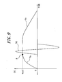
- the inventor observed that, when the load detection unit and the piezoelectric element drive unit are separately installed to control drive of the piezoelectric element, the output voltage Vs of the piezoelectric element detected by the load detection unit after drive of the piezoelectric element does not change as illustrated in FIG. 9 . That is, it was observed that the output voltage Vs is affected by the drive signal Vd applied from the piezoelectric element drive unit immediately before start of load detection or by the pressure load of the pressing object in pressing.
- the drive signal Vd is applied to the piezoelectric element to drive it.
- connection of the piezoelectric element is switched to the load detection unit and the output voltage Vs of the piezoelectric element monitored changes as illustrated in FIG. 10 , for example. That is, when the output voltage Vs of the piezoelectric element increases to a positive polarity side when the touch sensor starts being pressed, the output voltage Vs immediately after the piezoelectric element is driven increases to a negative polarity side relatively sharply. After that, the output voltage Vs represents a movement to gradually return to 0 V in accordance with self-discharge of accumulated charge.
- the tactile sensation is unexpectedly provided and the operator may have the feeling of strangeness.
- it may be considered, in a case illustrated in FIG 10 , for example, to set a negative standard voltage Vref against a positive standard voltage Vref for the load detection unit and to start detection of the pressure load immediately after drive of the piezoelectric element.
- the piezoelectric element is driven at a point Q when the output voltage Vs reaches the negative standard voltage Vref.
- the click sensation is continuously provided to the operator in a short period, which is different from the tactile sensation of the push-button switch, thereby inflicting the feeling of strangeness on the operator.
- the output voltage Vs after drive of the piezoelectric element may change from 0V to the positive polarity side, opposite to the output voltage Vs illustrated in FIG 10 .
- the output voltage Vs reaches the standard voltage Vref immediately after drive of the piezoelectric element, thereby the piezoelectric element is driven.
- the click sensation is provided to the operator continuously in a short period, which is also different from the tactile sensation of the push-button switch, thereby inflicting the feeling of strangeness on the operator.
- the piezoelectric element serving as the load sensor and the actuator to provide the tactile sensation and switching connection of the piezoelectric element between the load detection unit for an operation to detect the pressure load and the piezoelectric element drive unit for an operation to drive the piezoelectric element
- the output voltage Vs after drive of the piezoelectric element does not correspond to an actual pressure load of pressing. Accordingly, when the load detection unit resumes detection of the pressure load and controls drive of the piezoelectric element immediately after drive of the piezoelectric element, there may be a case that the tactile sensation is not appropriately provided to the operator.
- an object of the present invention in consideration of such conditions, is to provide an input apparatus capable of reducing cost and its size and allowing use of various types of piezoelectric elements, as well as appropriately providing the tactile sensation to the operator without inflicting the feeling of strangeness on the operator in operating the touch sensor.
- an input apparatus comprises :
- a first embodiment of the present invention is the input apparatus according to the first aspect, further comprising a discharge circuit configured to discharge the residual electric charge accumulated in the piezoelectric element, wherein the discharge circuit discharges, in the predetermined period, the residual charge accumulated in the piezoelectric element.
- a second embodiment of the present invention is the input apparatus according to the first aspect, wherein the predetermined period is 40 ms or less.
- the input apparatus uses the piezoelectric element as a load sensor to detect the pressure load on the touch face of the touch sensor and as an actuator to vibrate the touch face. It is thus possible to reduce the number of components and the cost as well as to save space for the components for downsizing the apparatus.
- the input apparatus drives the piezoelectric element with a drive signal alone without superimposing the drive signal on the output of the piezoelectric element.
- the load detection unit resumes detection of the pressure load after the predetermined period from drive of the piezoelectric element, it is possible to appropriately provide the tactile sensation to an operator without inflicting a feeling of strangeness on the operator.
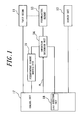
- FIG 1 is a functional block diagram illustrating a schematic configuration of an input apparatus according to a first embodiment of the present invention.
- This input apparatus has a touch sensor 11, a display unit 12, a piezoelectric element 13, a connection switchover unit 14, a piezoelectric element drive unit 15, and a control unit 17 to control an operation of each unit.
- the touch sensor 11 is connected to the control unit 17 and, under control of the control unit 17, detects a touch input to a touch face of the touch sensor 11 by a pressing object, such as a finger and the like, and provides the control unit 17 with position information of a touch position.
- the touch sensor 11 may be of a known type, such as a resistive film type, a capacitive type, an optical type and the like, and disposed on the display unit 12.
- the display unit 12 is connected to the control unit 17 and, under control of the control unit 17, displays an input object of an input button and the like such as a push-button switch (push-type button switch).
- the display unit 12 may be constituted by, for example, a liquid crystal display panel, an organic EL display panel and the like.
- the touch input to the input object displayed on the display unit 12 is detected by the control unit 17 based on the position information output from the touch sensor 11.
- the piezoelectric element 13 is mounted on the touch sensor 11 and designed to be bent (strained) under pressure of the touch face of the touch sensor 11.
- the piezoelectric element 13 is connected to the connection switchover unit 14 and selectively connected to the control unit 17 or the piezoelectric element drive unit 15 via the connection switchover unit 14.
- connection switchover unit 14 selectively connects the piezoelectric element 13 to the control unit 17 or the piezoelectric element drive unit 15 based on a connection switchover signal from the control unit 17.
- the piezoelectric element drive unit 15 may include a power amplifier and the like and outputs a predetermined drive signal to vibrate the piezoelectric element 13 under control of the control unit 17.
- the piezoelectric element 13 When connected to the control unit 17 via the connection switchover unit 14, the piezoelectric element 13 supplies the control unit 17 with a voltage (output signal) of electric charge generated by pressure on the touch face of the touch sensor 11.
- the piezoelectric element 13 is driven by the predetermined drive signal supplied from the piezoelectric element drive unit 15. Thereby, the touch sensor 11 is vibrated and provides a tactile sensation to the pressing object pressing the touch face.
- the control unit 17 may be, for example, a CPU and the like and includes a load detection unit 18 configured to detect the pressure load based on the output signal from the piezoelectric element 13 and determines whether the pressure load satisfies a standard to provide the tactile sensation.
- the control unit 17 controls the operation of each unit based on position information from the touch sensor 11, display information for the display unit 12, a result of determination by the load detection unit 18 and the like.
- FIG 2 is a circuit diagram illustrating an example of a configuration of the connection switchover unit 14 illustrated in FIG 1 .
- the connection switchover unit 14 includes two switch circuits 21, 22, which are semiconductor relays and the like, and an inverter 23. Each of the switch circuits 21, 22 has an ON/OFF contact point.
- the ON/OFF contact point of the switch circuit 21 is connected between a positive electrode terminal of the piezoelectric element 13 and an output terminal (not illustrated) of the piezoelectric element drive unit 15.
- the ON/Off contact point of the switch circuit 22 is connected between the positive electrode terminal of the piezoelectric element 13 and an analogue/digital conversion input terminal (not illustrated) of the control unit 17.
- the ON/OFF contact point of the switch circuit 21 is turned ON/OFF by a connection switchover signal a output from the control unit 17 through the inverter 23.
- the ON/OFF contact point of the switch circuit 22 is turned ON/OFF by the connection switchover signal a set forth above. Accordingly, when one of the ON/OFF contact points of the switch circuits 21, 22 is ON, the other is OFF.
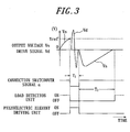
- FIG 3 is a timing chart illustrating a schematic operation of the input apparatus according to the present embodiment.
- FIG 3 illustrates an output signal (voltage) Vs and a drive signal Vd of the piezoelectric element 13, the connection switchover signal a, and motion states of the load detection unit 18 and the piezoelectric element drive unit 15 to the piezoelectric element 13.
- the control unit 17 sets the connection switchover signal ordinarily a at a high (H) level. Thereby, the switch circuit 21 of the switchover control unit 14 is turned OFF and the switch circuit 22 ON such that the piezoelectric element 13 is connected to the control unit 17.
- the control unit 17 monitors an output of the touch sensor 11.
- the load detection unit 18 of the control unit 17 detects the pressure load on the touch sensor 11 based on the output voltage Vs of the piezoelectric element 13 and determines whether the pressure load detected satisfies the standard to provide the tactile sensation.
- the control unit 17 sets the contact switchover signal a at a low (L) level for only a predetermined period T 1 .
- the switch circuit 21 of the switchover control unit 14 is turned ON and the switch circuit 22 OFF such that the piezoelectric element 13 is connected to the piezoelectric element drive unit 15.
- the control unit 17 controls the piezoelectric element drive unit 15 to output a predetermined drive signal Vd to drive the piezoelectric element 13.
- the touch panel 11 is vibrated such that the tactile sensation is provided to the pressing object pressing the touch face.
- the control unit 17 performs predetermined operations for the input object on the display unit 12 such as, for example, changing a display state, displaying a character corresponding to the input object in a predetermined display area, executing and processing application corresponding to the object, and the like.
- the control unit 17 sets the connection switchover signal a at the level H and turns the switch circuit 21 back to OFF and the switch circuit 22 back to ON. Thereby, the piezoelectric element 13 is disconnected from the piezoelectric element drive unit 15 and connected to the control unit 17.
- the load detection unit 18 neutralizes (cancels) the output voltage Vs from the piezoelectric element 13. Then, from the point when the predetermined period T 2 expires, the load detection unit 18 enables the output voltage Vs of the piezoelectric element 13 and resumes detection of the pressure load based on the output voltage Vs.
- the predetermined period T 1 to maintain the connection switchover signal a at the level L may be fixedly set (for example, approximately 10 ms) including a drive time of the piezoelectric element 13 or automatically set based on the drive time by the drive signal corresponding to the tactile sensation to provide.
- the predetermined period T 2 which is a period between drive of the piezoelectric element 13 and resumption of detection of the pressure load by the load detection unit 18, is set to be a sufficient time such that the residual electric charge in the piezoelectric element 13 is substantially completely discharged and also such that detection of the load of each input operation in continuous input operations and the like is not prevented.
- the predetermined period T 2 is, for example, 40 ms or less.
- the input apparatus uses the piezoelectric element 13 to serve as a load sensor to detect the pressure load on the touch face of the touch sensor 11 and as an actuator to vibrate the touch face such that the tactile sensation is provided to the pressing object.
- the same component is shared for a plurality of functions. It is thus possible to reduce the number of components and the cost as well as to save space for the components for downsizing the apparatus.
- the drive signal Vd may be supplied from the piezoelectric element drive unit 15 to the piezoelectric element 13 separately from the output voltage Vs of the piezoelectric element 13. Accordingly, it is not necessary to apply a voltage adding up the output voltage Vs and the drive signal voltage Vd. Thus the range of the working voltage is lowered and use of various types of the piezoelectric elements is enabled. Moreover, after driving the piezoelectric element 13, that is, after providing the tactile sensation first in accordance with increase in the pressure load of the touch input, the load detection unit 18 resumes detection of the pressure load when the predetermined period T 2 expires.
- the tactile sensation is not provided even if the output voltage Vs exceeds the standard voltage Vref in accordance with increase in the pressure by the pressing object during the predetermined period T 2 . It is thus possible to appropriately provide the tactile sensation to the operator without inflicting a feeling of strangeness on the operator due to providing an unexpected tactile sensation.
- FIG. 4 illustrates an exemplary housing structure of the touch sensor 11, the display unit 12 and the piezoelectric element13 illustrated in FIG. 1 ;
- FIG. 4(a) is a cross-sectional view of a main section, and
- FIG. 4(b) is a plane view of the main section.
- the display unit 12 is contained in a housing 31.
- the touch sensor 11 is disposed on the display unit 12 via insulators 32 made of elastic members. According to the present embodiment, the touch sensor 11 is disposed on the display unit 12 via the insulators 32 arranged at four corners outside a display area A of the display unit 12 illustrated by a chain double-dashed line in FIG. 4(b) .
- the housing 31 is provided with an upper cover 33 covering a surface area of the touch sensor 11 outside the display area of the display unit 12.
- an insulator 34 made of elastic member is arranged between the upper cover 33 and the touch sensor 11.
- the touch sensor 11 illustrated in FIG 4 may have, for example, a surface member having a touch face 11a and constituted by a transparent film or the glass, and a rear face member constituted by the glass or acryl.
- the touch sensor 11 is designed such that, when the touch face 11a is pressed down via the insulator 34, a pushed part and an entire touch sensor 11 are bent (strained) slightly in accordance with the pressure.
- the piezoelectric element 13 is provided on the rear face of the touch sensor 11 at a position covered by the upper cover 33 close to a periphery on one side or each of a plurality of sides, for example, three sides. These three piezoelectric elements 13 detect the pressure load on the touch face 11a of the touch sensor 11 and vibrate the touch sensor 11 such that the tactile sensation is provided to the pressing object pressing the touch face 11a. It is to be noted that the housing 31, the upper cover 33 and the insulator 34 illustrated in FIG 4(a) are omitted in FIG 4(b) .
- the three piezoelectric elements 13 are connected to the piezoelectric element drive unit 15 via the connection switchover unit 14 and driven by a common drive signal or individual drive signals.
- the three piezoelectric elements 13 supply the outputs in parallel to the load detection unit 18 via the connection switchover unit 14.
- the load detection unit 18 calculates the pressure load based on the output signals from the three piezoelectric elements 13.
- results of calculation of the pressure loads are approximately the same when the operator feels nearly the same pressure sensation (hard feeling, soft feeling and the like) at each position on the touch face 11a.
- the load detection unit 18 calculates the pressure load based on, for example, an average value of the outputs of the three piezoelectric elements 13, a weighted additional value and the like.
- the piezoelectric element drive unit 15 appropriately changes amplitude, a phase and the like of each of the drive signals in accordance with a position and a location on the touch face 11a such that an approximately identical feeling of a combination of the pressure sensation and the tactile sensation is obtained.
- the standard of the pressure load to provide the tactile sensation may be appropriately set in accordance with a load characteristic of an intended push-button switch in pressing.
- the standard is set to be equal to a load at which the touch sensor 11 responds to the touch input (synchronizing a timing to provide the tactile sensation with a timing of response to the touch input by the touch sensor 11) or to be higher than the load at which the touch sensor 11 responds to the touch input (setting the timing to provide the tactile sensation later than the timing of response to the touch input by the touch sensor 11).
- the standard is set by users as desired, such that an elder user may set it heavier (slower), whereas a user who often writes messages may set it lighter (quicker).
- the drive signal to drive the piezoelectric element 13 by the piezoelectric element drive unit 15 may be appropriately determined based on the tactile sensation to provide. For example, in order to provide a click sensation "Cli", which is obtained when pressing the push-button switch employed by the mobile terminal, the piezoelectric element drive unit 15 drives the piezoelectric element 13 as follows. Upon application of the pressure load satisfying the standard set forth above, the drive signal, for example, a sine wave with a constant frequency of, for example, 100 Hz to 200 Hz, preferably 170 Hz, for 1 period is applied to the piezoelectric element 13 such that the touch face 11 a is vibrated by approximately 15 ⁇ m while the pressure load satisfying the standard is applied thereto.
- the drive signal for example, a sine wave with a constant frequency of, for example, 100 Hz to 200 Hz, preferably 170 Hz, for 1 period is applied to the piezoelectric element 13 such that the touch face 11 a is vibrated by approximately 15 ⁇ m while the pressure load satisfying the standard
- the piezoelectric element drive unit 15 applies the drive signal, for example, a sine wave or a square wave with a frequency of, for example, approximately 200 Hz to 500 Hz, for 1 period to the piezoelectric element 13.
- the drive signal for example, a sine wave with a frequency of approximately 200 Hz to 500 Hz, for two or three periods is applied.
- the drive signal for example, a sine wave with a frequency of approximately 200 Hz to 500 Hz, for four or more periods is applied.
- information on the drive signals to provide those various tactile sensations is stored in a memory unit (not illustrated) such that the user suitably sets the drive signal to provide a desired tactile sensation. It is also preferable, based on the drive signal set, to automatically set the period T 1 , in which the connection switchover signal a is set at the level L.
- the control unit 17 does not drive the piezoelectric element 13 until the load applied to the touch sensor 11 calculated based on the output of the piezoelectric element 13 satisfies the standard to provide the tactile sensation (for example, 1.5 N). Thereby, a tactile sensation of the operator is stimulated. Then, when the load satisfies the standard, the control unit 17 controls the piezoelectric element drive unit 15 to drive the piezoelectric element 13 with the predetermined drive signal such that the touch face 11 a is vibrated to stimulate the tactile sensation. Thereby, the tactile sensation is provided to the operator such that the operator recognizes that the input operation is completed.
- the standard for example, 1.5 N.
- the operator performs the input operation with the touch sensor 11 feeling the realistic click sensation similar to that obtained when operating the push-button switch.
- the operator may not have the feeling of strangeness.
- the operator since the operator carries out the input operation in conjunction with perception to "have pressed" the touch sensor 11, it prevents erroneous inputs caused by mere tapping.
- the control unit 17 determines an input position according to a touch operation to the touch face 11a and changes a display state of the input object at a corresponding portion of the display unit 12. Then, when the pressure load on the touch face 11a detected based on the output from the piezoelectric element 12 satisfies the standard to provide the tactile sensation, the control unit 17 drives the piezoelectric element 13 to provide the tactile sensation and also execute a predetermined operation (for example, execution and processing of a program corresponding to the object) by confirming the input position.
- a predetermined operation for example, execution and processing of a program corresponding to the object
- the operator confirms that the input object is selected, by seeing a change of the display state of the input object displayed on the display unit 12. Moreover, since the click sensation is provided to the operator upon pressing the touch face 11 a, the operator recognizes that the input object selected is determined (executed). Thereby, it prevents erroneous inputs by a so-called wandering finger.
- FIG 5 is a functional block diagram illustrating a schematic configuration of an input apparatus according to a second embodiment of the present invention.
- This input apparatus has a discharge circuit 16 connected to the piezoelectric element 13 in addition to the configuration illustrated in FIG 1 and, after drive of the piezoelectric element 13, the discharge circuit 16 forces discharge of the residual electric charge remained in the piezoelectric element 13 to ground.
- the discharge circuit 16 has, for example, a resistor 41 and a switching transistor 42 for discharge.
- the switching transistor 42 has a collector connected to a positive polarity terminal of the piezoelectric element 13 and an emitter connected to ground.
- a base of the switching transistor 42 is connected to the control unit 17 via the resistor 41 such that a discharge control signal b is supplied from the control unit 17.
- Other configurations are the same as those in FIG. 1 , and thus components for the same functions are provided with identical reference signs and descriptions thereof are omitted.
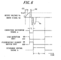
- FIG 6 is a timing chart illustrating a schematic operation of the input apparatus according to the present embodiment.
- the piezoelectric element drive unit 15 drives the piezoelectric element 13, that is, during a predetermined period T 3 after expiration of the predetermined period T 1 to set the connection switchover signal a at the level L
- the discharge control signal b is set at the level H. Accordingly, the switching transistor 42 is conducted such that the residual electric charge accumulated in the piezoelectric element 13 is forcibly discharged to ground via a collector-emitter pathway.
- the load detection unit 18 neutralizes (cancels) the output voltage Vs from the piezoelectric element 13 until expiration of the predetermined period T 3 in which the discharge control signal is set at the level H. Then, from a point when the predetermined period T 3 expires, the load detection unit 18 enables the output voltage Vs from the piezoelectric element 13 and resumes detection of the pressure load based on the output voltage Vs.
- Other operations are the same as those in the first embodiment, thus descriptions thereof are omitted.
- the predetermined period (discharge period) T 3 after drive of the piezoelectric element 13 and before resumption of detection of the pressure load by the load detection unit 18 may be set to be, for example, 30 ms, which is shorter than the predetermined period T 2 according to the first embodiment. Accordingly, in addition to the effect of the first embodiment, in so-called repetitive inputs to continuously carry out the input operation to the same input object displayed on the display unit 12, an effect is obtained such as to appropriately provide the tactile sensation at each input operation.
- FIG 7 is a timing chart illustrating a schematic operation of an input apparatus according to a third embodiment of the present invention.
- the input apparatus according to the present embodiment has the configuration illustrated in FIG 5 and provides the tactile sensation also when the pressing object is released from the touch face of the touch sensor 11.
- the load detection unit 18 has a first standard voltage Vref1 corresponding to the standard of the load to provide the tactile sensation in pressing (corresponding to the standard voltage Vref according to the first and second embodiments) and a second standard voltage Vref2 corresponding to a standard of the load to provide the tactile sensation in releasing.
- the second standard voltage Vref2 has a polarity different from that of the first standard voltage Vref1.
- the following is a description of the schematic operation of the input apparatus according to the present embodiment with reference to FIG. 5 .
- the control unit 17 determines that the position information from the touch sensor 11 indicates that an input is performed to the input object displayed on the display unit 12 and the load detection unit 18 determines that the output voltage Vs of the piezoelectric element 13 has reached the first standard voltage Vref1 corresponding to the standard of the load (for example, 1.5 N) to provide the tactile sensation
- the control unit 17 sets the connection switchover signal a at the level L for only the predetermined period T 1 .
- the piezoelectric element 13 is connected to the piezoelectric element drive unit 15 via the switchover control unit 14.
- the control unit 17 controls the piezoelectric element drive unit 15 to output the predetermined drive signal Vd to drive the piezoelectric element 13.
- the touch panel 11 is vibrated such that the tactile sensation is provided to the pressing object pressing the touch face.
- the control unit 17 sets the connection switchover signal a at the level H and changes the connection of the piezoelectric element 13 from the piezoelectric element drive unit 15 to the control unit 17. Simultaneously, the control unit 17 sets the discharge control signal b at the level H for a predetermined period (discharge period) T 4 and discharges the residual electric charge accumulated in the piezoelectric element 13 to ground via the collector-emitter pathway of the switching transistor 42.
- the load detection unit 18 does not detect the pressure load before expiration of the predetermined period T 4 , in which the discharge control signal b is at the level H. Then, from a point when the predetermined period T 4 expires, the load detection unit 18 resumes detection of the pressure load based on the output voltage Vs from the piezoelectric element 14.
- the predetermined period (discharge period) T 4 is set to be shorter than the predetermined period T 3 according to the second embodiment such as, for example, approximately 20 ms.
- the piezoelectric element 13 since the piezoelectric element 13 is connected to ground for the predetermined period T 4 to discharge the residual electric charge, the output voltage Vs of the piezoelectric element 13 is 0 V at an end of the predetermined period T4. Accordingly, if the touch sensor 11 is pressed by the pressing object at this point, the output voltage Vs of the piezoelectric element 13 is 0 V in that state. As a result, when the piezoelectric element is displaced returning to an original state in accordance with a release operation of the pressing object, the output voltage of the piezoelectric element 13 increases to the negative polarity side in accordance with the displacement.
- the control unit 17 sets the connection switchover signal a at the level L for the predetermined period T 1 and changes the connection of the piezoelectric element 13 from the control unit 17 to the piezoelectric element drive unit 15.
- the control unit 17 controls the piezoelectric element drive unit 15 to output the predetermined drive signal Vd to drive the piezoelectric element 13.
- the touch panel 11 is vibrated and the tactile sensation is provided to the pressing object pressing the touch face.
- the control unit 17 sets the connection switchover signal a at the level H and changes the connection of the piezoelectric element 13 from the piezoelectric element drive unit 15 to the control unit 17 and maintains the discharge control signal b at the level H for the predetermined period (discharge period) T 4 . Thereby, the residual electric charge accumulated in the piezoelectric element 13 is discharged. Then, from a point when the predetermined period T 4 for discharge by the discharge circuit 16 expires, the load detection unit 18 resumes detection of the pressure load based on the output voltage Vs of the piezoelectric element 14 and prepares for detection of a next touch input.
- the input apparatus offers the same effect as the above embodiments.
- the tactile sensation is provided also when the pressing object is released from the touch sensor 11, it is possible to provide a realistic operation sensation of the push-button switch such as a metal dome switch. That is, it is possible to provide a realistic click sensation "Cli” obtained when the metal dome is depressed in pressing and a realistic click sensation (in this case, release sensation) "Ck” obtained when the metal dome recovers from depression in releasing.
- the drive signal for the release sensation does not necessarily need to be the same as that for the click sensation.
- the tactile sensations "Cli”, “Ck”, “Click”, the "throbbing” sensation, the "jelly-like” sensation and the "vibrating” sensation set forth in the present specification are sensations obtained by the operator described in Japanese. Examples of the drive signals to provide actual tactile sensations are set forth above.
- the standard of the load to provide the release sensation may be set to be the same as the standard (for example, 1.5 N) to provide the click sensation in pressing set forth above, it is preferable to set the standard of the load to provide the release sensation to be 50-80 % lower than that to provide the click sensation in pressing (for example, 1 N).
- timings to provide the tactile sensations are synchronized with timings of sequential inputs when the same position (input object) is repetitively input (tapped), providing the realistic click sensation without the feeling of strangeness. That is, setting the standard of the load to provide the tactile sensation in releasing to be smaller than that in pressing enables to prevent the feeling of strangeness.
- setting the standard of the load to provide the tactile sensation in releasing to be approximately 50% or more of that in pressing contributes to a significant improvement in operability in the repetitive input.
- setting the standard of the load to provide the tactile sensation in releasing to be approximately 80% or less of that in pressing enables to deal with a faint load change in a holding state in the repetitive input.
- the switching transistor 42 of the discharge circuit 16 illustrated in FIG 5 may include a semiconductor relay and the like.
- the piezoelectric element 13 may have a known configuration such as monomorph, unimorph, bimorph and a laminated type, based on a size, vibration amplitude and the like of the touch sensor 11.
- the present invention is effectively applicable to the input apparatus in which the touch sensor functions as a touch switch for ON/OFF operations.
- the input apparatus according to the present invention drives the piezoelectric element when the pressure load detected based on the output of the piezoelectric element satisfies the standard to provide the tactile sensation.
- "when the pressure load detected based on the output of the piezoelectric element satisfies the standard to provide the tactile sensation” may include either "when the pressure load detected reaches a standard value to provide the tactile sensation", “when the pressure load detected exceeds the standard value to provide the tactile sensation", or "when the standard value to provide the tactile sensation is detected based on the output of the piezoelectric element".
Landscapes
- Engineering & Computer Science (AREA)
- General Engineering & Computer Science (AREA)
- Theoretical Computer Science (AREA)
- Human Computer Interaction (AREA)
- Physics & Mathematics (AREA)
- General Physics & Mathematics (AREA)
- Position Input By Displaying (AREA)
- User Interface Of Digital Computer (AREA)
- Push-Button Switches (AREA)
- Electronic Switches (AREA)
Claims (3)
- Eingabevorrichtung, die Folgendes umfasst:einen Berührungssensor (11), der konfiguriert ist, eine Berührungseingabe zu detektieren;ein piezoelektrisches Element (13), das an dem Berührungssensor (11) montiert ist;eine Beanspruchungsdetektionseiriheit (18), die konfiguriert ist, eine Druckbeanspruchung auf einer Berührungsfläche (11a) des Berührungssensors (11) anhand einer Ausgabe des piezoelektrischen Elements (13) zu detektieren und zu bestimmen, ob die Druckbeanspruchung einen Standard erfüllt, um eine taktile Empfindung bereitzustellen; undeine Ansteuerungseinheit (15) für das piezoelektrische Element, die konfiguriert ist, das piezoelektrische Element (13) anzusteuern, wenn die Beanspruchungsdetektionseinheit (18) bestimmt, dass die Druckbeanspruchung den Standard erfüllt, derart, dass für ein Objekt, das auf die Berührungsfläche (11a) drückt, die taktile Empfindung bereitgestellt wird, wobeidie Beanspruchungsdetektionseinheit (18) das Detektieren der Druckbeanspruchung wieder aufnimmt, wenn eine vorgegebene Zeitdauer seit dem Ansteuern des piezoelektrischen Elements (13) durch die Ansteuerungseinheit (15) für das piezoelektrische Element verstrichen ist, wobei die vorgegebene Zeitdauer so eingestellt ist, dass sie ausreicht, damit eine verbliebene elektrische Ladung in dem piezoelektrischen Element (13) im Wesentlichen abgeführt wird.
- Eingabevorrichtung nach Anspruch 1, die ferner eine Entladungsschaltung (16) umfasst, die konfiguriert ist, die verbliebene elektrische Ladung, die sich in dem piezoelektrischen Element (13) angesammelt hat, abzuführen, wobei
die Entladungsschaltung (16) in der vorgegebenen Zeitdauer die verbliebene Ladung, die sich in dem piezoelektrischen Element (13) angesammelt hat, abführt. - Eingabevorrichtung nach Anspruch 1, wobei die vorgegebene Zeitdauer 40 ms oder weniger beträgt.
Applications Claiming Priority (2)
| Application Number | Priority Date | Filing Date | Title |
|---|---|---|---|
| JP2009197394A JP2011048696A (ja) | 2009-08-27 | 2009-08-27 | 入力装置 |
| PCT/JP2010/005273 WO2011024460A1 (ja) | 2009-08-27 | 2010-08-26 | 入力装置 |
Publications (3)
| Publication Number | Publication Date |
|---|---|
| EP2472368A1 EP2472368A1 (de) | 2012-07-04 |
| EP2472368A4 EP2472368A4 (de) | 2013-03-20 |
| EP2472368B1 true EP2472368B1 (de) | 2015-07-15 |
Family
ID=43627579
Family Applications (1)
| Application Number | Title | Priority Date | Filing Date |
|---|---|---|---|
| EP10811516.3A Active EP2472368B1 (de) | 2009-08-27 | 2010-08-26 | Eingabevorrichtung |
Country Status (6)
| Country | Link |
|---|---|
| US (1) | US8823662B2 (de) |
| EP (1) | EP2472368B1 (de) |
| JP (1) | JP2011048696A (de) |
| KR (1) | KR20120048655A (de) |
| CN (1) | CN102483663B (de) |
| WO (1) | WO2011024460A1 (de) |
Families Citing this family (48)
| Publication number | Priority date | Publication date | Assignee | Title |
|---|---|---|---|---|
| US8587422B2 (en) | 2010-03-31 | 2013-11-19 | Tk Holdings, Inc. | Occupant sensing system |
| US9007190B2 (en) | 2010-03-31 | 2015-04-14 | Tk Holdings Inc. | Steering wheel sensors |
| JP5759230B2 (ja) | 2010-04-02 | 2015-08-05 | ティーケー ホールディングス,インコーポレーテッド | 手センサを有するステアリング・ホイール |
| WO2012049969A1 (ja) * | 2010-10-15 | 2012-04-19 | 株式会社村田製作所 | タッチ式入力装置およびその制御方法 |
| WO2012063497A1 (ja) * | 2010-11-11 | 2012-05-18 | 京セラ株式会社 | 入力装置および入力装置の制御方法 |
| WO2012169138A1 (ja) * | 2011-06-08 | 2012-12-13 | パナソニック株式会社 | 入力装置 |
| WO2013014942A1 (ja) * | 2011-07-27 | 2013-01-31 | 京セラ株式会社 | 電子機器 |
| JPWO2013105516A1 (ja) * | 2012-01-13 | 2015-05-11 | 京セラ株式会社 | 電子機器及び電子機器の制御方法 |
| JP5590345B2 (ja) * | 2012-02-01 | 2014-09-17 | シャープ株式会社 | 入出力装置、入出力方法、及び入出力プログラム |
| WO2013154720A1 (en) | 2012-04-13 | 2013-10-17 | Tk Holdings Inc. | Pressure sensor including a pressure sensitive material for use with control systems and methods of using the same |
| WO2013175778A1 (ja) | 2012-05-22 | 2013-11-28 | 京セラ株式会社 | 電子機器及びパネル装置 |
| JP2013242806A (ja) * | 2012-05-22 | 2013-12-05 | Kyocera Corp | 電子機器 |
| US9493342B2 (en) | 2012-06-21 | 2016-11-15 | Nextinput, Inc. | Wafer level MEMS force dies |
| WO2014008377A1 (en) | 2012-07-05 | 2014-01-09 | Ian Campbell | Microelectromechanical load sensor and methods of manufacturing the same |
| WO2014043664A1 (en) | 2012-09-17 | 2014-03-20 | Tk Holdings Inc. | Single layer force sensor |
| KR102006151B1 (ko) | 2012-11-27 | 2019-10-10 | 삼성디스플레이 주식회사 | 터치를 인식하고 전기 촉각 자극을 제공하는 표시 장치 및 그 구동 방법 |
| CN105027025A (zh) * | 2013-01-27 | 2015-11-04 | 微软科技许可有限公司 | 对唤醒信号改善响应时间的数字化系统 |
| CN103281004B (zh) * | 2013-06-05 | 2016-01-20 | 中山市昊源电器设备有限公司 | 一种高功率高压脉冲电源电路 |
| JP6143179B2 (ja) * | 2013-06-26 | 2017-06-07 | 株式会社Soken | 操作入力装置 |
| WO2015064007A1 (ja) * | 2013-10-28 | 2015-05-07 | 京セラ株式会社 | 触感呈示装置及び触感呈示装置の制御方法 |
| CA2929723C (en) * | 2013-12-12 | 2020-09-15 | Qualcomm Incorporated | Micromechanical ultrasonic transducers and display |
| CN105934661B (zh) | 2014-01-13 | 2019-11-05 | 触控解决方案股份有限公司 | 微型强化圆片级mems力传感器 |
| KR101677334B1 (ko) | 2014-10-24 | 2016-11-17 | 엘지전자 주식회사 | 냉장고 도어 |
| WO2016072802A1 (en) | 2014-11-07 | 2016-05-12 | Lg Electronics Inc. | Metal touch sensing apparatus, and home appliance having metal touch sensing apparatus and method for controlling the same |
| CN105588400B (zh) | 2014-11-07 | 2018-04-13 | Lg电子株式会社 | 冰箱及冰箱控制方法 |
| EP3018824A1 (de) * | 2014-11-10 | 2016-05-11 | Aito Interactive Oy | Piezoelektrischer Sensor und Vorrichtung mit einem piezoelektrischen Sensor |
| KR101659180B1 (ko) | 2014-12-22 | 2016-09-22 | 엘지전자 주식회사 | 터치 센서 어셈블리 및 터치 센서 어셈블리가 구비된 냉장고 도어 |
| KR101659181B1 (ko) | 2014-12-22 | 2016-09-30 | 엘지전자 주식회사 | 터치 센서 어셈블리 및 터치 센서 어셈블리가 구비된 냉장고 도어 |
| KR101668922B1 (ko) | 2014-12-24 | 2016-10-24 | 엘지전자 주식회사 | 디스플레이 어셈블리가 구비된 가전제품 및 그 제조 방법 |
| KR101668921B1 (ko) | 2014-12-24 | 2016-10-24 | 엘지전자 주식회사 | 터치 센서 어셈블리 및 터치 센서 어셈블리가 구비된 냉장고 도어 |
| KR101659184B1 (ko) | 2014-12-24 | 2016-09-22 | 엘지전자 주식회사 | 터치 센서 어셈블리 및 터치 센서 어셈블리 제조 방법 |
| DE102015206978A1 (de) * | 2015-04-17 | 2016-10-20 | Volkswagen Aktiengesellschaft | Bedienvorrichtung in einem Kraftfahrzeug zum Bestimmen einer Berührposition auf einer Berührfläche |
| US10466119B2 (en) | 2015-06-10 | 2019-11-05 | Nextinput, Inc. | Ruggedized wafer level MEMS force sensor with a tolerance trench |
| KR101736608B1 (ko) | 2015-11-27 | 2017-05-16 | 엘지전자 주식회사 | 냉장고 |
| US20180121011A1 (en) * | 2016-10-31 | 2018-05-03 | iGlass Technology, Inc. | Electrochromic touchscreen device |
| EP4701393A2 (de) | 2017-02-09 | 2026-02-25 | Nextinput, Inc. | Integrierte digitale kraftsensoren und zugehörige verfahren zur herstellung |
| WO2018148510A1 (en) | 2017-02-09 | 2018-08-16 | Nextinput, Inc. | Integrated piezoresistive and piezoelectric fusion force sensor |
| CN107340924B (zh) | 2017-07-14 | 2020-01-31 | 京东方科技集团股份有限公司 | 触控电路、触控面板、显示面板和显示装置 |
| EP3655740A4 (de) | 2017-07-19 | 2021-07-14 | Nextinput, Inc. | Spannungstransferstapelung in einem mems-kraftsensor |
| WO2019023309A1 (en) | 2017-07-25 | 2019-01-31 | Nextinput, Inc. | FORCE SENSOR AND INTEGRATED FINGERPRINTS |
| WO2019023552A1 (en) | 2017-07-27 | 2019-01-31 | Nextinput, Inc. | PIEZORESISTIVE AND PIEZOELECTRIC FORCE SENSOR ON WAFER AND METHODS OF MANUFACTURING THE SAME |
| JP6852795B2 (ja) * | 2017-09-11 | 2021-03-31 | 富士通株式会社 | 制御装置、電子機器、及び、電子機器の制御方法 |
| WO2019079420A1 (en) | 2017-10-17 | 2019-04-25 | Nextinput, Inc. | SHIFT TEMPERATURE COEFFICIENT COMPENSATION FOR FORCE SENSOR AND STRAIN GAUGE |
| WO2019090057A1 (en) | 2017-11-02 | 2019-05-09 | Nextinput, Inc. | Sealed force sensor with etch stop layer |
| WO2019099821A1 (en) | 2017-11-16 | 2019-05-23 | Nextinput, Inc. | Force attenuator for force sensor |
| CN108375431B (zh) * | 2018-02-26 | 2020-06-30 | 京东方科技集团股份有限公司 | 压力检测电路、压力检测方法、压力检测模组和显示装置 |
| US11302859B2 (en) * | 2018-09-20 | 2022-04-12 | Boréas Technologies Inc. | Zero-power wake-up sensing circuit in piezoelectric haptic feedback |
| US10962427B2 (en) | 2019-01-10 | 2021-03-30 | Nextinput, Inc. | Slotted MEMS force sensor |
Family Cites Families (19)
| Publication number | Priority date | Publication date | Assignee | Title |
|---|---|---|---|---|
| JPS62296317A (ja) * | 1986-06-17 | 1987-12-23 | 日立金属株式会社 | 圧電素子駆動回路 |
| JPH0720703B2 (ja) * | 1986-11-20 | 1995-03-08 | ブラザー工業株式会社 | 圧電素子駆動回路 |
| JPH04369543A (ja) | 1991-06-19 | 1992-12-22 | Seiko Epson Corp | 圧電素子駆動回路 |
| JPH08234892A (ja) * | 1995-02-28 | 1996-09-13 | Smk Corp | 抵抗感圧型タブレット及び抵抗感圧型タブレットのペンオン検出しきい値設定方法 |
| JP3987182B2 (ja) * | 1998-01-26 | 2007-10-03 | Idec株式会社 | 情報表示装置および操作入力装置 |
| US6518521B1 (en) * | 1999-09-02 | 2003-02-11 | Hutchinson Technology Incorporated | Switchable shunts for integrated lead suspensions |
| DE10117956B4 (de) * | 2001-04-10 | 2004-04-08 | Schott Glas | Berührungsschalter mit einer Bedienfläche |
| JP2002339872A (ja) * | 2001-05-17 | 2002-11-27 | Matsushita Electric Ind Co Ltd | 圧電ポンプの駆動方法及び装置 |
| FI112415B (fi) * | 2001-11-28 | 2003-11-28 | Nokia Oyj | Pietsosähköinen käyttöliittymä |
| JP2003288158A (ja) | 2002-01-28 | 2003-10-10 | Sony Corp | タクタイル・フィードバック機能を持つ携帯型機器 |
| US20050088417A1 (en) | 2003-10-24 | 2005-04-28 | Mulligan Roger C. | Tactile touch-sensing system |
| KR101130150B1 (ko) | 2003-11-17 | 2012-03-28 | 소니 주식회사 | 입력 장치, 정보 처리 장치, 리모트 컨트롤 장치 및 입력장치의 제어 방법 |
| JP2006048302A (ja) | 2004-08-03 | 2006-02-16 | Sony Corp | 圧電複合装置、その製造方法、その取扱方法、その制御方法、入出力装置及び電子機器 |
| JP4543863B2 (ja) | 2004-10-05 | 2010-09-15 | ソニー株式会社 | 触覚機能付きの入出力装置及び電子機器 |
| JP2007086990A (ja) | 2005-09-21 | 2007-04-05 | Smk Corp | タッチパネル |
| CN1845043A (zh) | 2006-04-29 | 2006-10-11 | 怡利电子工业股份有限公司 | 具有按压压力侦测的触控板 |
| JP2008130055A (ja) * | 2006-11-27 | 2008-06-05 | Sony Corp | タッチパネルディスプレイ装置および駆動方法並びに電子機器 |
| US7808154B2 (en) * | 2007-01-19 | 2010-10-05 | Konica Minolta Opto, Inc. | Actuator unit, driving device for information recording/reading head, information recording/reading apparatus, and method for driving the actuator unit |
| JP2008199880A (ja) * | 2007-01-19 | 2008-08-28 | Konica Minolta Opto Inc | アクチュエータユニット、情報記録読出ヘッド駆動装置、情報記録読出装置、およびアクチュエータユニットの駆動方法 |
-
2009
- 2009-08-27 JP JP2009197394A patent/JP2011048696A/ja active Pending
-
2010
- 2010-08-26 WO PCT/JP2010/005273 patent/WO2011024460A1/ja not_active Ceased
- 2010-08-26 US US13/392,873 patent/US8823662B2/en active Active
- 2010-08-26 EP EP10811516.3A patent/EP2472368B1/de active Active
- 2010-08-26 KR KR1020127005016A patent/KR20120048655A/ko not_active Ceased
- 2010-08-26 CN CN201080038148.4A patent/CN102483663B/zh active Active
Also Published As
| Publication number | Publication date |
|---|---|
| EP2472368A1 (de) | 2012-07-04 |
| JP2011048696A (ja) | 2011-03-10 |
| EP2472368A4 (de) | 2013-03-20 |
| WO2011024460A1 (ja) | 2011-03-03 |
| CN102483663B (zh) | 2015-03-25 |
| US8823662B2 (en) | 2014-09-02 |
| CN102483663A (zh) | 2012-05-30 |
| US20120154318A1 (en) | 2012-06-21 |
| KR20120048655A (ko) | 2012-05-15 |
Similar Documents
| Publication | Publication Date | Title |
|---|---|---|
| EP2472368B1 (de) | Eingabevorrichtung | |
| EP2472367B1 (de) | Eingabevorrichtung und verfahren zur steuerung der eingabevorrichtung | |
| US20190138100A1 (en) | Input apparatus and control method for input apparatus | |
| US9208663B2 (en) | Input apparatus and control method for input apparatus | |
| EP2472366B1 (de) | Tastempfindungsaktivierungsvorrichtung und steuerverfahren für die tastempfindungsaktivierungsvorrichtung | |
| EP2472365B1 (de) | Tastempfindungsaktivierungsvorrichtung und steuerverfahren für die tastempfindungsaktivierungsvorrichtung | |
| EP2515209B1 (de) | Tastempfindungsbereitstellungsvorrichtung | |
| US8947388B2 (en) | Input apparatus | |
| EP2472364B1 (de) | Eingabevorrichtung | |
| JP5710214B2 (ja) | 入力装置および入力装置の制御方法 | |
| JP5143881B2 (ja) | 触感呈示装置および触感呈示装置の制御方法 |
Legal Events
| Date | Code | Title | Description |
|---|---|---|---|
| PUAI | Public reference made under article 153(3) epc to a published international application that has entered the european phase |
Free format text: ORIGINAL CODE: 0009012 |
|
| 17P | Request for examination filed |
Effective date: 20120227 |
|
| AK | Designated contracting states |
Kind code of ref document: A1 Designated state(s): AL AT BE BG CH CY CZ DE DK EE ES FI FR GB GR HR HU IE IS IT LI LT LU LV MC MK MT NL NO PL PT RO SE SI SK SM TR |
|
| DAX | Request for extension of the european patent (deleted) | ||
| REG | Reference to a national code |
Ref country code: DE Ref legal event code: R079 Ref document number: 602010025959 Country of ref document: DE Free format text: PREVIOUS MAIN CLASS: G06F0003041000 Ipc: G06F0003010000 |
|
| A4 | Supplementary search report drawn up and despatched |
Effective date: 20130218 |
|
| RIC1 | Information provided on ipc code assigned before grant |
Ipc: G06F 3/041 20060101ALI20130212BHEP Ipc: G06F 3/01 20060101AFI20130212BHEP |
|
| 17Q | First examination report despatched |
Effective date: 20140618 |
|
| GRAP | Despatch of communication of intention to grant a patent |
Free format text: ORIGINAL CODE: EPIDOSNIGR1 |
|
| INTG | Intention to grant announced |
Effective date: 20150122 |
|
| GRAS | Grant fee paid |
Free format text: ORIGINAL CODE: EPIDOSNIGR3 |
|
| GRAA | (expected) grant |
Free format text: ORIGINAL CODE: 0009210 |
|
| AK | Designated contracting states |
Kind code of ref document: B1 Designated state(s): AL AT BE BG CH CY CZ DE DK EE ES FI FR GB GR HR HU IE IS IT LI LT LU LV MC MK MT NL NO PL PT RO SE SI SK SM TR |
|
| REG | Reference to a national code |
Ref country code: CH Ref legal event code: EP Ref country code: GB Ref legal event code: FG4D |
|
| REG | Reference to a national code |
Ref country code: IE Ref legal event code: FG4D |
|
| REG | Reference to a national code |
Ref country code: AT Ref legal event code: REF Ref document number: 737100 Country of ref document: AT Kind code of ref document: T Effective date: 20150815 |
|
| REG | Reference to a national code |
Ref country code: DE Ref legal event code: R096 Ref document number: 602010025959 Country of ref document: DE |
|
| REG | Reference to a national code |
Ref country code: AT Ref legal event code: MK05 Ref document number: 737100 Country of ref document: AT Kind code of ref document: T Effective date: 20150715 |
|
| REG | Reference to a national code |
Ref country code: NL Ref legal event code: MP Effective date: 20150715 |
|
| REG | Reference to a national code |
Ref country code: LT Ref legal event code: MG4D |
|
| PG25 | Lapsed in a contracting state [announced via postgrant information from national office to epo] |
Ref country code: GR Free format text: LAPSE BECAUSE OF FAILURE TO SUBMIT A TRANSLATION OF THE DESCRIPTION OR TO PAY THE FEE WITHIN THE PRESCRIBED TIME-LIMIT Effective date: 20151016 Ref country code: NO Free format text: LAPSE BECAUSE OF FAILURE TO SUBMIT A TRANSLATION OF THE DESCRIPTION OR TO PAY THE FEE WITHIN THE PRESCRIBED TIME-LIMIT Effective date: 20151015 Ref country code: LV Free format text: LAPSE BECAUSE OF FAILURE TO SUBMIT A TRANSLATION OF THE DESCRIPTION OR TO PAY THE FEE WITHIN THE PRESCRIBED TIME-LIMIT Effective date: 20150715 Ref country code: LT Free format text: LAPSE BECAUSE OF FAILURE TO SUBMIT A TRANSLATION OF THE DESCRIPTION OR TO PAY THE FEE WITHIN THE PRESCRIBED TIME-LIMIT Effective date: 20150715 Ref country code: FI Free format text: LAPSE BECAUSE OF FAILURE TO SUBMIT A TRANSLATION OF THE DESCRIPTION OR TO PAY THE FEE WITHIN THE PRESCRIBED TIME-LIMIT Effective date: 20150715 |
|
| PG25 | Lapsed in a contracting state [announced via postgrant information from national office to epo] |
Ref country code: PL Free format text: LAPSE BECAUSE OF FAILURE TO SUBMIT A TRANSLATION OF THE DESCRIPTION OR TO PAY THE FEE WITHIN THE PRESCRIBED TIME-LIMIT Effective date: 20150715 Ref country code: ES Free format text: LAPSE BECAUSE OF FAILURE TO SUBMIT A TRANSLATION OF THE DESCRIPTION OR TO PAY THE FEE WITHIN THE PRESCRIBED TIME-LIMIT Effective date: 20150715 Ref country code: HR Free format text: LAPSE BECAUSE OF FAILURE TO SUBMIT A TRANSLATION OF THE DESCRIPTION OR TO PAY THE FEE WITHIN THE PRESCRIBED TIME-LIMIT Effective date: 20150715 Ref country code: AT Free format text: LAPSE BECAUSE OF FAILURE TO SUBMIT A TRANSLATION OF THE DESCRIPTION OR TO PAY THE FEE WITHIN THE PRESCRIBED TIME-LIMIT Effective date: 20150715 Ref country code: PT Free format text: LAPSE BECAUSE OF FAILURE TO SUBMIT A TRANSLATION OF THE DESCRIPTION OR TO PAY THE FEE WITHIN THE PRESCRIBED TIME-LIMIT Effective date: 20151116 Ref country code: SE Free format text: LAPSE BECAUSE OF FAILURE TO SUBMIT A TRANSLATION OF THE DESCRIPTION OR TO PAY THE FEE WITHIN THE PRESCRIBED TIME-LIMIT Effective date: 20150715 |
|
| REG | Reference to a national code |
Ref country code: CH Ref legal event code: PL |
|
| REG | Reference to a national code |
Ref country code: DE Ref legal event code: R097 Ref document number: 602010025959 Country of ref document: DE |
|
| PG25 | Lapsed in a contracting state [announced via postgrant information from national office to epo] |
Ref country code: SK Free format text: LAPSE BECAUSE OF FAILURE TO SUBMIT A TRANSLATION OF THE DESCRIPTION OR TO PAY THE FEE WITHIN THE PRESCRIBED TIME-LIMIT Effective date: 20150715 Ref country code: DK Free format text: LAPSE BECAUSE OF FAILURE TO SUBMIT A TRANSLATION OF THE DESCRIPTION OR TO PAY THE FEE WITHIN THE PRESCRIBED TIME-LIMIT Effective date: 20150715 Ref country code: LI Free format text: LAPSE BECAUSE OF NON-PAYMENT OF DUE FEES Effective date: 20150831 Ref country code: CZ Free format text: LAPSE BECAUSE OF FAILURE TO SUBMIT A TRANSLATION OF THE DESCRIPTION OR TO PAY THE FEE WITHIN THE PRESCRIBED TIME-LIMIT Effective date: 20150715 Ref country code: CH Free format text: LAPSE BECAUSE OF NON-PAYMENT OF DUE FEES Effective date: 20150831 Ref country code: MC Free format text: LAPSE BECAUSE OF FAILURE TO SUBMIT A TRANSLATION OF THE DESCRIPTION OR TO PAY THE FEE WITHIN THE PRESCRIBED TIME-LIMIT Effective date: 20150715 Ref country code: EE Free format text: LAPSE BECAUSE OF FAILURE TO SUBMIT A TRANSLATION OF THE DESCRIPTION OR TO PAY THE FEE WITHIN THE PRESCRIBED TIME-LIMIT Effective date: 20150715 |
|
| PLBE | No opposition filed within time limit |
Free format text: ORIGINAL CODE: 0009261 |
|
| STAA | Information on the status of an ep patent application or granted ep patent |
Free format text: STATUS: NO OPPOSITION FILED WITHIN TIME LIMIT |
|
| PG25 | Lapsed in a contracting state [announced via postgrant information from national office to epo] |
Ref country code: RO Free format text: LAPSE BECAUSE OF FAILURE TO SUBMIT A TRANSLATION OF THE DESCRIPTION OR TO PAY THE FEE WITHIN THE PRESCRIBED TIME-LIMIT Effective date: 20150715 |
|
| REG | Reference to a national code |
Ref country code: IE Ref legal event code: MM4A |
|
| 26N | No opposition filed |
Effective date: 20160418 |
|
| PG25 | Lapsed in a contracting state [announced via postgrant information from national office to epo] |
Ref country code: IS Free format text: LAPSE BECAUSE OF FAILURE TO SUBMIT A TRANSLATION OF THE DESCRIPTION OR TO PAY THE FEE WITHIN THE PRESCRIBED TIME-LIMIT Effective date: 20150715 |
|
| REG | Reference to a national code |
Ref country code: FR Ref legal event code: PLFP Year of fee payment: 7 |
|
| PG25 | Lapsed in a contracting state [announced via postgrant information from national office to epo] |
Ref country code: IE Free format text: LAPSE BECAUSE OF NON-PAYMENT OF DUE FEES Effective date: 20150826 |
|
| PG25 | Lapsed in a contracting state [announced via postgrant information from national office to epo] |
Ref country code: SI Free format text: LAPSE BECAUSE OF FAILURE TO SUBMIT A TRANSLATION OF THE DESCRIPTION OR TO PAY THE FEE WITHIN THE PRESCRIBED TIME-LIMIT Effective date: 20150715 |
|
| PG25 | Lapsed in a contracting state [announced via postgrant information from national office to epo] |
Ref country code: MT Free format text: LAPSE BECAUSE OF FAILURE TO SUBMIT A TRANSLATION OF THE DESCRIPTION OR TO PAY THE FEE WITHIN THE PRESCRIBED TIME-LIMIT Effective date: 20150715 |
|
| PG25 | Lapsed in a contracting state [announced via postgrant information from national office to epo] |
Ref country code: HU Free format text: LAPSE BECAUSE OF FAILURE TO SUBMIT A TRANSLATION OF THE DESCRIPTION OR TO PAY THE FEE WITHIN THE PRESCRIBED TIME-LIMIT; INVALID AB INITIO Effective date: 20100826 Ref country code: BG Free format text: LAPSE BECAUSE OF FAILURE TO SUBMIT A TRANSLATION OF THE DESCRIPTION OR TO PAY THE FEE WITHIN THE PRESCRIBED TIME-LIMIT Effective date: 20150715 Ref country code: SM Free format text: LAPSE BECAUSE OF FAILURE TO SUBMIT A TRANSLATION OF THE DESCRIPTION OR TO PAY THE FEE WITHIN THE PRESCRIBED TIME-LIMIT Effective date: 20150715 |
|
| PG25 | Lapsed in a contracting state [announced via postgrant information from national office to epo] |
Ref country code: NL Free format text: LAPSE BECAUSE OF FAILURE TO SUBMIT A TRANSLATION OF THE DESCRIPTION OR TO PAY THE FEE WITHIN THE PRESCRIBED TIME-LIMIT Effective date: 20150715 Ref country code: CY Free format text: LAPSE BECAUSE OF FAILURE TO SUBMIT A TRANSLATION OF THE DESCRIPTION OR TO PAY THE FEE WITHIN THE PRESCRIBED TIME-LIMIT Effective date: 20150715 |
|
| REG | Reference to a national code |
Ref country code: FR Ref legal event code: PLFP Year of fee payment: 8 |
|
| PG25 | Lapsed in a contracting state [announced via postgrant information from national office to epo] |
Ref country code: BE Free format text: LAPSE BECAUSE OF NON-PAYMENT OF DUE FEES Effective date: 20150831 |
|
| PG25 | Lapsed in a contracting state [announced via postgrant information from national office to epo] |
Ref country code: TR Free format text: LAPSE BECAUSE OF FAILURE TO SUBMIT A TRANSLATION OF THE DESCRIPTION OR TO PAY THE FEE WITHIN THE PRESCRIBED TIME-LIMIT Effective date: 20150715 |
|
| PG25 | Lapsed in a contracting state [announced via postgrant information from national office to epo] |
Ref country code: LU Free format text: LAPSE BECAUSE OF NON-PAYMENT OF DUE FEES Effective date: 20150826 |
|
| PG25 | Lapsed in a contracting state [announced via postgrant information from national office to epo] |
Ref country code: MK Free format text: LAPSE BECAUSE OF FAILURE TO SUBMIT A TRANSLATION OF THE DESCRIPTION OR TO PAY THE FEE WITHIN THE PRESCRIBED TIME-LIMIT Effective date: 20150715 |
|
| REG | Reference to a national code |
Ref country code: FR Ref legal event code: PLFP Year of fee payment: 9 |
|
| PG25 | Lapsed in a contracting state [announced via postgrant information from national office to epo] |
Ref country code: AL Free format text: LAPSE BECAUSE OF FAILURE TO SUBMIT A TRANSLATION OF THE DESCRIPTION OR TO PAY THE FEE WITHIN THE PRESCRIBED TIME-LIMIT Effective date: 20150715 |
|
| P01 | Opt-out of the competence of the unified patent court (upc) registered |
Effective date: 20230505 |
|
| PGFP | Annual fee paid to national office [announced via postgrant information from national office to epo] |
Ref country code: DE Payment date: 20250702 Year of fee payment: 16 |
|
| PGFP | Annual fee paid to national office [announced via postgrant information from national office to epo] |
Ref country code: IT Payment date: 20250722 Year of fee payment: 16 |
|
| PGFP | Annual fee paid to national office [announced via postgrant information from national office to epo] |
Ref country code: GB Payment date: 20250703 Year of fee payment: 16 |
|
| PGFP | Annual fee paid to national office [announced via postgrant information from national office to epo] |
Ref country code: FR Payment date: 20250703 Year of fee payment: 16 |