EP2472489B1 - Steuervorrichtung, Rundfunkempfänger, Verfahren zur Steuerung des Rundfunkempfängers und Verfahren zur Dienstbereitstellung - Google Patents
Steuervorrichtung, Rundfunkempfänger, Verfahren zur Steuerung des Rundfunkempfängers und Verfahren zur Dienstbereitstellung Download PDFInfo
- Publication number
- EP2472489B1 EP2472489B1 EP11188994.5A EP11188994A EP2472489B1 EP 2472489 B1 EP2472489 B1 EP 2472489B1 EP 11188994 A EP11188994 A EP 11188994A EP 2472489 B1 EP2472489 B1 EP 2472489B1
- Authority
- EP
- European Patent Office
- Prior art keywords
- broadcast receiver
- control
- control device
- menu
- displayed
- Prior art date
- Legal status (The legal status is an assumption and is not a legal conclusion. Google has not performed a legal analysis and makes no representation as to the accuracy of the status listed.)
- Active
Links
Images


Classifications
-
- H—ELECTRICITY
- H04—ELECTRIC COMMUNICATION TECHNIQUE
- H04N—PICTORIAL COMMUNICATION, e.g. TELEVISION
- H04N21/00—Selective content distribution, e.g. interactive television or video on demand [VOD]
- H04N21/60—Network structure or processes for video distribution between server and client or between remote clients; Control signalling between clients, server and network components; Transmission of management data between server and client, e.g. sending from server to client commands for recording incoming content stream; Communication details between server and client
- H04N21/63—Control signaling related to video distribution between client, server and network components; Network processes for video distribution between server and clients or between remote clients, e.g. transmitting basic layer and enhancement layers over different transmission paths, setting up a peer-to-peer communication via Internet between remote STB's; Communication protocols; Addressing
-
- G—PHYSICS
- G08—SIGNALLING
- G08C—TRANSMISSION SYSTEMS FOR MEASURED VALUES, CONTROL OR SIMILAR SIGNALS
- G08C17/00—Arrangements for transmitting signals characterised by the use of a wireless electrical link
- G08C17/02—Arrangements for transmitting signals characterised by the use of a wireless electrical link using a radio link
-
- H—ELECTRICITY
- H04—ELECTRIC COMMUNICATION TECHNIQUE
- H04N—PICTORIAL COMMUNICATION, e.g. TELEVISION
- H04N21/00—Selective content distribution, e.g. interactive television or video on demand [VOD]
- H04N21/40—Client devices specifically adapted for the reception of or interaction with content, e.g. set-top-box [STB]; Operations thereof
- H04N21/41—Structure of client; Structure of client peripherals
- H04N21/4104—Peripherals receiving signals from specially adapted client devices
- H04N21/4126—The peripheral being portable, e.g. PDAs or mobile phones
- H04N21/41265—The peripheral being portable, e.g. PDAs or mobile phones having a remote control device for bidirectional communication between the remote control device and client device
-
- H—ELECTRICITY
- H04—ELECTRIC COMMUNICATION TECHNIQUE
- H04N—PICTORIAL COMMUNICATION, e.g. TELEVISION
- H04N21/00—Selective content distribution, e.g. interactive television or video on demand [VOD]
- H04N21/40—Client devices specifically adapted for the reception of or interaction with content, e.g. set-top-box [STB]; Operations thereof
- H04N21/41—Structure of client; Structure of client peripherals
- H04N21/422—Input-only peripherals, i.e. input devices connected to specially adapted client devices, e.g. global positioning system [GPS]
- H04N21/42204—User interfaces specially adapted for controlling a client device through a remote control device; Remote control devices therefor
- H04N21/42206—User interfaces specially adapted for controlling a client device through a remote control device; Remote control devices therefor characterized by hardware details
- H04N21/4222—Remote control device emulator integrated into a non-television apparatus, e.g. a PDA, media center or smart toy
-
- H—ELECTRICITY
- H04—ELECTRIC COMMUNICATION TECHNIQUE
- H04N—PICTORIAL COMMUNICATION, e.g. TELEVISION
- H04N21/00—Selective content distribution, e.g. interactive television or video on demand [VOD]
- H04N21/40—Client devices specifically adapted for the reception of or interaction with content, e.g. set-top-box [STB]; Operations thereof
- H04N21/47—End-user applications
- H04N21/482—End-user interface for programme selection
-
- G—PHYSICS
- G08—SIGNALLING
- G08C—TRANSMISSION SYSTEMS FOR MEASURED VALUES, CONTROL OR SIMILAR SIGNALS
- G08C2201/00—Transmission systems of control signals via wireless link
- G08C2201/30—User interface
- G08C2201/32—Remote control based on movements, attitude of remote control device
-
- G—PHYSICS
- G08—SIGNALLING
- G08C—TRANSMISSION SYSTEMS FOR MEASURED VALUES, CONTROL OR SIMILAR SIGNALS
- G08C2201/00—Transmission systems of control signals via wireless link
- G08C2201/90—Additional features
- G08C2201/93—Remote control using other portable devices, e.g. mobile phone, PDA, laptop
Definitions
- aspects of the exemplary embodiments relate to a control device, a broadcast receiver, a method for controlling a broadcast receiver, and a method for providing a service, and more particularly, to a control device which allows a user to easily change a display menu of the control device according to a user's preference and circumstances, a broadcast receiver, a method for controlling a broadcast receiver, and a method for providing a service thereof.
- a broadcast receiver is a device which, when in use, receives digital and/or analog satellite broadcast signals, converts the digital satellite broadcast or analog satellite broadcast transmitted from a broadcast station, and displays the converted signal or transmits the converted signal to an external display apparatus.
- the broadcast receiver also receives a video and/or an audio signal input from various external apparatuses, such as a video player, a DVD player, and a Blu-ray disc player, converts the signal into a transport stream (TS) signal, and displays the converted signal or transmits the converted signal to the external display apparatus.
- TS transport stream
- such a broadcast receiver may include Internet Protocol Television (IPTV) such as a digital TV and Video On Demand (VOD) and a set-top box (STB).
- IPTV Internet Protocol Television
- VOD Video On Demand
- STB set-top box
- a broadcast receiver is capable of providing various types of information using a menu and thus, a user is provided with various menus.
- a user In order to select a desired menu through a remote controller, a user needs to press a button on the remote controller corresponding to the desired menu and check an image formed on the display of the broadcast receiver located at some distance from where the user is located to confirm that the desired menu item is selected.
- This operation is inconvenient to the user since the user needs to perform the input operation in the remote controller while also checking the images displayed on the receiver which can be located some distance away from the user.
- the user in order to operate the menu correctly, the user must repeatedly shift their focus between the remote controller in their hand and the display screen at a distance, which can be difficult and inconvenient for the user.
- WO 2010/016853 discloses an apparatus and method for controlling an electronic device.
- EP-A-2 141 675 discloses a remote controller to set operating mode using analysis of the remote controller.
- An aspect of the exemplary embodiments relates to a control device which allows a user to easily select a device displaying a menu according to a user's preference and circumstances, a broadcast receiver, a method for controlling a broadcast receiver and a method for providing a service thereof characterized in that wherein the determination unit is arranged to identify a grip direction of a user with respect to the control device and determines the control mode of the control device corresponding to the identified grip direction.
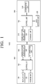
- FIG. 1 is a block diagram illustrating the configuration of a home network system according to an exemplary embodiment.
- the home network system 1000 comprises a broadcast receiver 100 and a control device 200.
- the broadcast receiver 100 provides a user with an image or video/audio information, and may be embodied as a digital TV, STB, PC, notebook computer, personal media player (PMP), and so on.
- the broadcast receiver 100 may include a display unit 110, a storage unit 120, a communication interface unit 130, a determination unit 140, and a control unit 150.
- the display unit 110 may display information provided by the broadcast receiver 100.
- the display unit 110 may be an apparatus which is capable of receiving and outputting data such as a touch pad device, or may be an image display apparatus such as a liquid crystal display (LCD), plasma display panel (PDP) and cathode ray-tube (CRT).
- the control device 200 may receive a service screen provided by the broadcast receiver 100.
- the display unit 110 of the broadcast receiver 100 may display a menu for selecting a service by a user. Specifically, if the determination unit 140 which will be explained later determines that a menu is displayed on the broadcast receiver 100, a menu for selecting a service by a user may be displayed. On the other hand, if the determination unit 140 determines that a menu is displayed only on the control device 200, the display unit 110 of the broadcast receiver 100 may not display a menu.
- the display unit 110 may be an internal component of the digital TV, and if the broadcast receiver 110 is a set-top box, the display unit 110 may be an external component or apparatus (such as a monitor or a TV connected to the set-top box).
- the storage unit 120 may store contents corresponding to various services supported by the broadcast receiver 100.
- the storage unit 120 may store a plurality of user interface windows corresponding to an operation mode of the broadcast receiver 100.
- the storage unit 120 may be embodied as a storage medium inside the broadcast receiver 100, an external storage medium such as a removable disk including a USB memory, a storage medium connected to a separate host, or a web server connected to the broadcast receiver 100 via a network.
- the communication interface unit 130 transmits menu information. Specifically, the communication interface unit 130 may form a link to the communication interface unit 210 of the control device 200 and transmit menu information to the communication interface unit 130 through bi-directional wireless communication. In addition, the communication interface unit 130 may transmit a user interface window corresponding to an operation mode of the broadcast receiver 100 according to a request from the control device 200.
- the communication interface unit 130 may receive a control command of a user from the control device 200. Meanwhile, such transmission of menu information may be performed in accordance with a request from the control device 200, or may be performed without any particular request.
- the bi-directional communication may include all of the existing communication technologies such as Bluetooth (BT), Radio Frequency (RF), Wireless Fidelity (Wi-Fi), High Definition Multimedia Interface - Consumer Electronic Control (HDMI-CEC), and Wireless HDMI-CEC and all of the future bi-directional wireless communication technologies.
- BT Bluetooth
- RF Radio Frequency
- Wi-Fi Wireless Fidelity
- HDMI-CEC Wireless HDMI-CEC
- the menu information is information to help a user select a service of a broadcast receiver and may include information regarding channel, current volume, play time, remaining play time, current time, Electronic Program Guide (EPG), an operation mode of a broadcast receiver, and a current screen displayed on a broadcast receiver.
- EPG Electronic Program Guide
- the communication interface unit 130 may receive the menu information and the user interface window from an external server (not shown). Specifically, the communication interface unit 130 may receive the menu information and the user interface window from an external server which provides information such as EPG information or an external server of a manufacturer of a control device or a broadcast receiver.
- the determination unit 140 determines an apparatus in which to display a menu for controlling the broadcast receiver 100. Specifically, the determination unit 140 may receive information regarding a control mode determined by the control device 200 and determine in which apparatus to display the menu. For example, if a control mode determined by the control device 200 is a first control mode, the determination unit 140 may determine that the menu is to be displayed on the broadcast receiver 100, and if a control mode determined by the control device 200 is a second control mode, the determination unit 140 may determine that the menu is to be displayed on a control device.
- the determination unit 140 may also identify a grip direction of a user with respect to the control device 200. For example, the grip direction may be determined using a photographing sensor. As another example, the control device 200 may determine the grip direction and inform the broadcasr receiver 100 of the current grip direction. The determination unit 140 may determine an apparatus in which to display a menu according to the identified grip direction. In particular, the determination unit 140 may determine whether to display the menu by the display unit 110 or by the control device 200.
- the determination unit 140 may determine that a menu is to be displayed on the broadcast receiver 100, which is the first control mode, and if the identified grip direction of a user with respect to the control device 200 is a horizontal direction, the determination unit 140 may determine that a menu is to be displayed on the control device 200, which is the second control mode.
- the control unit 150 controls each component of the broadcast receiver 100. Specifically, if the determination unit 140 determines that a menu is to be displayed on the broadcast receiver 100, which is the first control mode, the control unit 150 may control the display unit 110 to display the menu on the broadcast receiver 100. Alternatively, if the determination unit 140 determines that a menu is to be displayed on the control device 200, which is the second control mode, the control unit 150 may control the display unit 110 not to display the menu on the broadcast receiver 100. Meanwhile, menu information may be transmitted to the control device 200 only when it is determined that the menu information is to be displayed on the control device 200, i.e. when a control mode of the control device 200 is the second control mode.
- control unit 150 may control a service operation or a service state of the broadcast receiver 100 according to a received control command and provides a service accordingly. For example, if the broadcast receiver 100 receives a control command of 'TV channel up' from the control device 200, the control unit 150 may provide a command to the TV in which a TV channel is changed. If the control device 200 requests screen information displayed on the broadcast receiver 100, the control unit 150 may control the communication interface unit 130 to transmit the screen information being displayed on the display unit 110 of the broadcast receiver 100 to the control device 200. Accordingly, a user may view the same screen information displayed on the broadcast receiver 100 also on the control device 200.
- the control device 200 controls the broadcast receiver 100 using bi-directional wireless communication and may be embodied as a remote controller, a mobile phone, an MP3 player, a navigator, or a digital photo frame.
- the control device 200 may include a communication interface unit 210, a storage unit 220, a user interface unit 230, a determination unit 240, and a control unit 250.
- the communication interface unit 210 requests the broadcast receiver 100 to send menu information. Specifically, the communication interface unit 210 may form a link to perform bi-directional wireless communication with the communication interface unit 130 of the broadcast receiver 100, request menu information to be displayed on the user interface unit 230 which will be explained later through the formed link, and receive the menu information. Meanwhile, the communication interface unit 210 may request the broadcast receiver 100 to send menu information only when a control mode of the control device 200 determined by the determination unit 240 which will be explained later is in the second control mode. When menu information is requested, information regarding a control mode determined by the determination unit 240 which will be explained later may be transmitted to the broadcast receiver 100.
- Such a request for menu information may be made to an external server (not shown).
- the communication interface unit 210 may request a broadcast receiver 100 which is communicable with an external server (not shown) or an external server itself to send menu information and receive the menu information accordingly.
- the communication interface unit 210 may transmit a control command received from the user interface unit 230 which will be explained later to the broadcast receiver 100.
- the storage unit 220 may store broadcast information received through the communication interface unit 210 and a user interface window corresponding to an operation mode of the broadcast receiver 100.
- the storage unit 220 may be embodied as a storage medium in the control device 200 or as an external storage medium such as a removable disk including a USB memory and a web server via a network.
- a plurality of user interface windows stored in the storage unit 220 may be provided.
- the plurality of user interface windows are pre-determined and may be stored in the storage unit 220 ready to be used when needed.
- the user interface windows may be provided from the broadcast receiver 100.
- the user interface unit 230 displays a user interface window to receive a control command and receives a control command for the broadcast receiver 100.
- the user interface unit 230 has a plurality of function keys through which a user may set or select various functions supported by the broadcast receiver 100 and display a plurality of user interface windows for controlling the broadcast receiver 100.
- the user interface unit 230 may be embodied as an apparatus which is capable of inputting and outputting data simultaneously such as a touch pad or as an apparatus which combines a key pad with a display apparatus.
- the user interface unit 230 may display a user interface window according to an operation mode of the broadcast receiver 100. Specifically, if the broadcast receiver 100 is displaying a TV broadcast, the user interface unit 230 may include various modes such as a TV control mode, a VTR control mode, and a search control mode according to the operation of the broadcast receiver 100. That is, if a user watches a TV using a broadcast receiver, a user interface window customized to control the TV may be displayed on the user interface unit 230. Alternatively, if a user watches a DVD using a broadcast receiver, a user interface window customized to watch the DVD may be displayed on the interface unit 230.
- various modes such as a TV control mode, a VTR control mode, and a search control mode according to the operation of the broadcast receiver 100. That is, if a user watches a TV using a broadcast receiver, a user interface window customized to control the TV may be displayed on the user interface unit 230. Alternatively, if a user watches a DVD using a broadcast receiver, a user
- the user interface unit 230 may display received menu information on a user interface window. Specifically, the user interface unit 230 may display menu information received through the communication interface unit 210 along with a user interface window according to the above-mentioned operation mode. Such a user interface window will be explained with reference to FIGS. 4 to 6 .
- the determination unit 240 determines a control mode of the control device 200. Specifically, the determination unit 240 may control the control unit 250 to control the user interface unit 230 to display a user interface window according to the control mode of the control device 200. The determination unit 240 may further determine a location or positioning of the menu on the user interface window according to the control mode selected by a user through the displayed user interface window.
- the control mode may include a first control mode where a menu having only an area for receiving a control command regarding a broadcast receiver is displayed on a user interface window (that is, a mode where the broadcast receiver displays a menu) and a second control mode where a menu showing menu information is displayed on a user interface window (that is, a mode where a control device displays a menu).
- the determination unit 240 may also identify a grip direction of a user with respect to the control device 200, or how a user holds the control device 200. As an example, the grip direction is determined using a gyro sensor. The determination unit 240 may determine a control mode corresponding to the grip direction of the user. For example, if the grip direction of a user is in a vertical direction with respect to the user, or in other words if the user holds the control device 200 in a vertical direction, the determination unit 240 may determine a control mode as the first control mode in which only an area for receiving a control command regarding a broadcast receiver 100 is displayed on a user interface window. If the grip direction of a user is in a horizontal direction with respect to the user, the determination unit 240 may determine a control mode as the second control mode in which received menu information is displayed on a user interface window.
- the control unit 250 controls each component of the control device 200. Specifically, if the determination unit 240 determines a control mode as the first control mode, the control unit 250 may control the user interface unit 230 to display a user interface window according to the operation mode of the broadcast receiver 100. If the determination unit 240 determines a control mode as the second control mode, the control unit 250 may control the user interface unit 230 to display received menu information along with a user interface window according to the operation mode of the broadcast receiver 100.
- control unit 250 may control the communication interface unit 110 to transmit the input control command to the broadcast receiver 100.
- the control unit 250 may control the control device 200 to display a screen being displayed on the broadcast receiver 100 on a user interface. Specifically, if it is determined that the control device 200 is disposed in a horizontal direction with respect to a user, the control unit 250 may request the broadcast receiver 100 to transmit a screen currently being displayed on the broadcast receiver 100 to the control device 200 and control the user interface unit 230 to display the screen received from the broadcast receiver 100.
- control device displays a location where a menu is displayed on the menu or on the control device according to a user's preference and circumstance, thereby improving user convenience.
- control device 200 controls only one broadcast receiver 100, but the control device 200 may control a plurality of broadcast receivers 100.
- FIG. 2 is a view illustrating an example of connection of a home network system 1000 according to an exemplary embodiment.
- the home network system 1000 includes the broadcast receiver 100 and the control device 200.
- the broadcast receiver 100 and the control device 200 are connected by performing bi-directional communication. Accordingly, the broadcast receiver 100 may transmit menu information to the control device 200 and also receive a user's control command using bi-directional communication.
- the broadcast receiver 100 may display a menu 111 on the display unit 110 in accordance with a user's control command. Specifically, if the control device 200 operates in the first control mode as described above, menu information is displayed on the broadcast receiver 100.
- the control device 200 may display menu information received from the broadcast receiver 100 as illustrated in FIGS. 4 and 5 .
- the broadcast receiver 100 may stop displaying the menu.
- the user interface unit 230 of the control device 200 may display a user interface window including a first area 231 for receiving a user's control command and a second area 232 for receiving a control mode.
- the first area 231 is an area for receiving a user's control command and may display a user interface window as illustrated in FIGS. 3 to 5 according to an operation mode of the broadcast receiver 100 and a control mode of the control device 200.
- the second area 232 is an area for receiving a control mode and may be displayed in the form of a slide bar as illustrated in FIG. 2 .
- FIGS. 3A - 3D are views illustrating examples of a user interface windows which can be displayed on a user interface unit of the control device 200 if the control device 200 is operated in the first control mode.
- the user interface window 310 of the control device 200 displays a user interface window which is optimized to control TV watching as a displayable user interface window.
- the user interface window 320 of the control device 200 displays a user interface window which is optimized to input a control command for game operation as a displayable user interface window.
- the user interface window 330 of the control device 200 displays a user interface window which is optimized to input a number as a displayable user interface window.
- the user interface window 340 of the control device 200 displays a user interface window which is optimized to control DVD watching as a displayable user interface window.
- control device 200 provides a user interface window optimized to the operation mode of the broadcast receiver 100 and thus, a user may control the broadcast receiver 100 conveniently.
- FIGS. 4 and 5 are views illustrating an example of a user interface window which can be displayed on a user interface unit of the control device 200 when the control device 200 is operated in the second control mode.
- the user interface window 400 displays a user interface window which is optimized to control TV watching along with menu information (information regarding a channel currently selectable by a user) as a displayable user interface window.
- the user may easily identify which channel is currently displayed on the broadcast receiver 100 and to which channel the current channel may be changed through the menu information displayed on the control device 200.
- the user interface window 500 displays menu information, which is, a user's search result as a displayable user interface window.
- a user may check the search result through the control device 200 and input a search command and perform additional search on the control device 200 directly. Therefore, user convenience may be enhanced.
- FIG. 6 is a view illustrating an example of an operation of a user interface unit when the control device 200 is gripped in a horizontal direction.
- the control device 200 is disposed in a horizontal direction with respect to a user, the screen being displayed on the broadcast receiver 100 is displayed on a user interface.
- the screen displayed on the broadcast receiver 100 may be displayed on the control device 200 according to a grip direction of the control device 200.
- user convenience may be enhanced.
- FIG. 7 is a flowchart to explain a method for providing a service according to an exemplary embodiment.
- an apparatus where a menu for controlling a broadcast receiver to be displayed is determined (S710),specifically the apparatus is determined by receiving information regarding a control mode.
- the control mode is determined by the control device 200, by identifying a grip direction of a user with respect to the control device 200 using a photographing or gyro sensor.
- menu information is displayed (S730) on the broadcast receiver.
- menu information is transmitted to a control device 200 (S740). Specifically, if it is determined that the menu is to be displayed on the control device 200, information which helps a user to select a desired service of a broadcast receiver 100 (such as, channel information, current volume, play time, remaining play time, current time, Electronic Program Guide (EPG), an operation mode of a broadcast receiver 100, and a current screen) is displayed on a broadcast receiver 100. Meanwhile, such transmission operation may always be provided to a control device 200 regardless of the above-mentioned control mode.
- EPG Electronic Program Guide
- a service corresponding to the received control command may be provided (S760) to the broadcast receiver 100.
- the broadcast receiver 100 receives a 'TV channel up' control command from the control device 200
- a TV service or command to change a TV channel may be provided to the broadcast receiver 100.
- the received control command is a command to provide screen information
- the screen information currently being displayed on the broadcast receiver 100 is transmitted to the control device 200 so that the screen being displayed on the broadcast receiver 100 is also displayed on the control device 200.
- the method for providing a service allows a user to receive a service by controlling a broadcast receiver 100 through a remote mobile device, thereby enhancing user convenience.
- the method for providing a service illustrated in FIG. 7 may be performed not only in a broadcast receiver 100 having the configuration of FIG. 1 but also in a broadcast receiver 100 having other configurations.
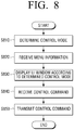
- FIG. 8 is a flowchart to explain a method for controlling a broadcast receiver according to another exemplary embodiment.
- a control mode according to an apparatus where a menu is to be displayed is determined (S810). Specifically, a user interface window for receiving at least one control mode from among a plurality of control modes is displayed and a selected control mode may be determined as a control mode of the control device 200 through the displayed user interface window.
- the control mode may include the first control mode in which a menu is displayed on the broadcast receiver 100 and the second control mode in which a menu is displayed on the control device 200.
- a user's grip direction with respect to the control device 200 may be identified using a gyro sensor and the above determination may be performed according to the identified grip direction. This has been explained above with respect to the determination unit 240, so further description will not be provided.
- menu information is requested and received from a broadcast receiver 100 (820). Specifically, menu information such as channel information, current volume, play time, remaining play time, current time, Electronic Program Guide (EPG), and an operation mode of a broadcast receiver 100 may be requested and received from a broadcast receiver 100. Such a request for menu information may be made only when a control mode is determined to be the second control mode.
- EPG Electronic Program Guide
- the received menu information and a user interface window according to the determined control mode are displayed (S830). Specifically, if the determined control mode is the first control mode, a user interface window according to an operation mode of the broadcast receiver 100 (that is, a user interface window without menu information) is displayed, and if the determined control mode is the second control mode, menu information may also be displayed on a user interface window according to an operation mode of the broadcast receiver 100.
- the method for controlling a broadcast receiver 100 provides a user interface window which is optimized according to an operation mode of the broadcast receiver 100, and a user may easily select a location where a menu is to be displayed according to a user interface window or a grip method of a control device 200.
- the method for controlling a broadcast receiver 100 illustrated in FIG. 8 may be performed not only in a control device 200 having configuration of FIG. 1 but also in a control device 200 having other configurations.
Landscapes
- Engineering & Computer Science (AREA)
- Multimedia (AREA)
- Signal Processing (AREA)
- Human Computer Interaction (AREA)
- Computer Networks & Wireless Communication (AREA)
- Physics & Mathematics (AREA)
- General Physics & Mathematics (AREA)
- Two-Way Televisions, Distribution Of Moving Picture Or The Like (AREA)
- User Interface Of Digital Computer (AREA)
- Selective Calling Equipment (AREA)
- Circuits Of Receivers In General (AREA)
Claims (9)
- Steuervorrichtung (200), die einen Rundfunkempfänger (100) steuert, die Folgendes umfasst:eine Kommunikationsschnittstelleneinheit (210), die konfiguriert ist, mit dem Rundfunkempfänger (100) zu kommunizieren;eine Berührungsanzeigeeinheit, die konfiguriert ist, eine Berührungseingabe zu empfangen;einen Sensor, der konfiguriert ist, eine Greifrichtung der Steuervorrichtung zu erfassen, die von einem Anwender gehalten wird;eine Steuereinheit (250), die konfiguriert ist zum:Identifizieren, ob sich die Steuervorrichtung in einer ersten Steuerungsbetriebsart, die einer vertikalen Greifrichtung entspricht, oder einer zweiten Steuerungsbetriebsart, die einer horizontalen Greifrichtung entspricht, befindet, auf der Grundlage der Greifrichtung, die durch den Sensor erfasst wird,Steuern der Berührungsanzeigeeinheit, eine Anwenderschnittstelle, UI, zum Steuern des Rundfunkempfängers anzuzeigen, als Antwort auf das Identifizieren, dass sich die Steuervorrichtung in der ersten Steuerungsbetriebsart befindet, undSteuern der Berührungsanzeigeeinheit, Menüinformationen anzuzeigen, die vom Rundfunkempfänger empfangen werden, als Antwort auf das Identifizieren, dass sich die Steuervorrichtung in der zweiten Steuerungsbetriebsart befindet, wobei die Menüinformationen dieselben Menüinformationen wie diejenigen, die aktuell auf einem Bildschirm des Rundfunkempfängers angezeigt werden, sind.
- Steuervorrichtung nach einem der vorhergehenden Ansprüche, wobei die Menüinformationen Kanalinformationen und/oder eine aktuelle Lautstärke und/oder eine Abspielzeit und/oder eine verbleibende Abspielzeit und/oder eine aktuelle Uhrzeit und/oder einen elektronischen Programmführer, EPG, und/oder eine Betriebsart eines Rundfunkempfängers (100) enthalten.
- Rundfunkempfänger (100), der Folgendes umfasst:eine Anzeigeeinheit (110), die Menüinformationen anzeigen kann, die verwendet werden, um den Rundfunkempfänger (100) zu steuern;eine Kommunikationsschnittstelleneinheit (130), die konfiguriert ist, Informationen an die Steuervorrichtung (200) zu senden und einen Steuerbefehl von der Steuervorrichtung (200) zu empfangen; undeine Steuereinheit (150), die einen Dienst gemäß einem Steuerbefehl bereitstellt, der von der Steuervorrichtung (200) empfangen wird;wobei der Rundfunkempfänger (100) ferner eine Bestimmungseinheit (140) umfasst, die konfiguriert ist zum:Identifizieren, ob sich die Steuervorrichtung in einer ersten Steuerungsbetriebsart, die einer vertikalen Greifrichtung entspricht, oder einer zweiten Steuerungsbetriebsart, die einer horizontalen Greifrichtung entspricht, befindet, auf der Grundlage der Greifrichtung, die durch den Sensor erfasst wird,Steuern der Anzeigeeinheit, Menüinformationen anzuzeigen, als Antwort auf das Identifizieren, dass sich die Steuervorrichtung in der ersten Steuerungsbetriebsart befindet.
- Rundfunkempfänger nach Anspruch 3, wobei die Menüinformationen Kanalinformationen und/oder eine aktuelle Lautstärke und/oder eine Abspielzeit und/oder eine verbleibende Abspielzeit und/oder eine aktuelle Tageszeit und/oder einen elektronischen Programmführer, EPG, und/oder eine Betriebsart eines Rundfunkempfängers und/oder Bildschirminformationen, die auf dem Rundfunkempfänger angezeigt werden, enthalten.
- Verfahren zum Steuern einer Steuervorrichtung (200), die einen Rundfunkempfänger (100) steuert, wobei das Verfahren Folgendes umfasst:Erfassen einer Greifrichtung der Steuervorrichtung, die von einem Anwender gehalten wird, durch einen Sensor;Identifizieren, ob sich die Steuervorrichtung in einer ersten Steuerungsbetriebsart, die einer vertikalen Greifrichtung entspricht, oder einer zweiten Steuerungsbetriebsart, die einer horizontalen Greifrichtung entspricht, befindet, auf der Grundlage der Greifrichtung;Anzeigen einer Anwenderschnittstelle, UI, zum Steuern des Rundfunkempfängers als Antwort auf das Identifizieren, dass sich die Steuervorrichtung in der ersten Steuerungsbetriebsart befindet; undAnzeigen von Menüinformationen, die vom Rundfunkempfänger empfangen werden, als Antwort auf das Identifizieren, dass sich die Steuervorrichtung in der zweiten Steuerungsbetriebsart befindet, wobei die Menüinformationen dieselben Menüinformationen wie diejenigen, die aktuell auf einem Bildschirm des Rundfunkempfängers angezeigt werden, sind.
- Verfahren nach Anspruch 5, wobei die mehreren Steuerungsbetriebsarten eine erste Steuerungsbetriebsart, in der lediglich ein Bereich zum Empfangen eines Befehls, um den Rundfunkempfänger (100) zu steuern, auf dem Anwenderschnittstellenfenster (400) der Steuervorrichtung (200) angezeigt wird, und eine zweite Betriebsart, in der die empfangenen Menüinformationen auf dem Anwenderschnittstellenfenster (400) der Steuervorrichtung (200) angezeigt werden, enthalten.
- Verfahren nach Anspruch 6, wobei der Bestimmungsschritt das Anzeigen eines Anwenderschnittstellenfensters (400) zum Empfangen eines Anwenderbefehls, um die erste Steuerungsbetriebsart und/oder die zweite Steuerungsbetriebsart auszuwählen, und das Bestimmen der Steuerungsbetriebsart durch das angezeigte Anwenderschnittstellenfenster umfasst.
- Verfahren zum Bereitstellen eines Dienstes eines Rundfunkempfängers (100), wobei das Verfahren Folgendes umfasst:Bestimmen, ob ein Menü, das den Rundfunkempfänger (100) steuert, durch den Rundfunkempfänger (100) oder durch eine zugehörige Steuervorrichtung (200) angezeigt werden soll;dann, wenn bestimmt wird, dass das Menü auf dem Rundfunkempfänger (100) angezeigt werden soll, Anzeigen des Menüs auf einer Anzeigeeinheit (110) des Rundfunkempfängers (100);dann, wenn bestimmt wird, dass das Menü auf der Steuervorrichtung (200) angezeigt werden soll, Senden von Menüinformationen an die Steuervorrichtung (200) und wahlweise Anzeigen des Menüs auf der Steuervorrichtung (200) ;Empfangen eines Steuerbefehls von der Steuervorrichtung (200) als Antwort auf die angezeigten Menüinformationen; undBereitstellen eines Dienstes des Rundfunkempfängers (100), der dem empfangenen Steuerbefehl entspricht;Identifizieren, ob sich die Steuervorrichtung in einer ersten Steuerungsbetriebsart, die einer vertikalen Greifrichtung entspricht, oder einer zweiten Steuerungsbetriebsart, die einer horizontalen Greifrichtung entspricht, befindet, auf der Grundlage der Greifrichtung, die durch den Sensor erfasst wird;Steuern der Anzeigeeinheit, ein Menü anzuzeigen, als Antwort auf das Identifizieren, dass sich die Steuervorrichtung in der ersten Steuerungsbetriebsart befindet.
- Steuervorrichtung nach Anspruch 1, wobei die Steuereinheit konfiguriert ist zum:Empfangen von Informationen in Bezug auf eine Betriebsart des Rundfunkempfängers über die Kommunikationsschnittstelleneinheit; undSteuern der Berührungsanzeigeeinheit der UI zum Steuern des Rundfunkempfängers gemäß der Betriebsart des Rundfunkempfängers als Antwort auf das Identifizieren, dass sich die Steuervorrichtung in der ersten Steuerungsbetriebsart befindet, die einer vertikalen Greifrichtung entspricht.
Priority Applications (2)
| Application Number | Priority Date | Filing Date | Title |
|---|---|---|---|
| EP20198642.9A EP3779918A1 (de) | 2010-12-31 | 2011-11-14 | Steuerungsvorrichtung, rundfunkempfänger, verfahren zur steuerung des rundfunkempfängers und verfahren zur dienstbereitstellung |
| EP20164405.1A EP3693937B1 (de) | 2010-12-31 | 2011-11-14 | Steuerungsvorrichtung, rundfunkempfänger, verfahren zur steuerung des rundfunkempfängers und verfahren zur dienstbereitstellung |
Applications Claiming Priority (1)
| Application Number | Priority Date | Filing Date | Title |
|---|---|---|---|
| KR1020100140242A KR101713788B1 (ko) | 2010-12-31 | 2010-12-31 | 제어 디바이스, 방송수신장치, 방송수신장치 제어 방법 및 서비스 제공 방법 |
Related Child Applications (3)
| Application Number | Title | Priority Date | Filing Date |
|---|---|---|---|
| EP20198642.9A Division EP3779918A1 (de) | 2010-12-31 | 2011-11-14 | Steuerungsvorrichtung, rundfunkempfänger, verfahren zur steuerung des rundfunkempfängers und verfahren zur dienstbereitstellung |
| EP20164405.1A Division EP3693937B1 (de) | 2010-12-31 | 2011-11-14 | Steuerungsvorrichtung, rundfunkempfänger, verfahren zur steuerung des rundfunkempfängers und verfahren zur dienstbereitstellung |
| EP20164405.1A Division-Into EP3693937B1 (de) | 2010-12-31 | 2011-11-14 | Steuerungsvorrichtung, rundfunkempfänger, verfahren zur steuerung des rundfunkempfängers und verfahren zur dienstbereitstellung |
Publications (3)
| Publication Number | Publication Date |
|---|---|
| EP2472489A2 EP2472489A2 (de) | 2012-07-04 |
| EP2472489A3 EP2472489A3 (de) | 2013-09-25 |
| EP2472489B1 true EP2472489B1 (de) | 2020-09-30 |
Family
ID=45023671
Family Applications (3)
| Application Number | Title | Priority Date | Filing Date |
|---|---|---|---|
| EP11188994.5A Active EP2472489B1 (de) | 2010-12-31 | 2011-11-14 | Steuervorrichtung, Rundfunkempfänger, Verfahren zur Steuerung des Rundfunkempfängers und Verfahren zur Dienstbereitstellung |
| EP20198642.9A Pending EP3779918A1 (de) | 2010-12-31 | 2011-11-14 | Steuerungsvorrichtung, rundfunkempfänger, verfahren zur steuerung des rundfunkempfängers und verfahren zur dienstbereitstellung |
| EP20164405.1A Active EP3693937B1 (de) | 2010-12-31 | 2011-11-14 | Steuerungsvorrichtung, rundfunkempfänger, verfahren zur steuerung des rundfunkempfängers und verfahren zur dienstbereitstellung |
Family Applications After (2)
| Application Number | Title | Priority Date | Filing Date |
|---|---|---|---|
| EP20198642.9A Pending EP3779918A1 (de) | 2010-12-31 | 2011-11-14 | Steuerungsvorrichtung, rundfunkempfänger, verfahren zur steuerung des rundfunkempfängers und verfahren zur dienstbereitstellung |
| EP20164405.1A Active EP3693937B1 (de) | 2010-12-31 | 2011-11-14 | Steuerungsvorrichtung, rundfunkempfänger, verfahren zur steuerung des rundfunkempfängers und verfahren zur dienstbereitstellung |
Country Status (3)
| Country | Link |
|---|---|
| US (6) | US9723350B2 (de) |
| EP (3) | EP2472489B1 (de) |
| KR (1) | KR101713788B1 (de) |
Families Citing this family (8)
| Publication number | Priority date | Publication date | Assignee | Title |
|---|---|---|---|---|
| CN103491405B (zh) * | 2013-08-30 | 2018-06-05 | 小米科技有限责任公司 | 遥控系统、遥控器、显示设备及遥控方法 |
| US10965991B2 (en) | 2013-09-06 | 2021-03-30 | Gracenote, Inc. | Displaying an actionable element over playing content |
| CN103826156B (zh) * | 2014-03-17 | 2017-09-19 | 华为技术有限公司 | 终端遥控方法、机顶盒、移动终端及网页服务器 |
| JP6381774B2 (ja) * | 2015-02-24 | 2018-08-29 | 三菱電機株式会社 | リモートコントローラ、操作画面表示方法及びプログラム |
| US20160366481A1 (en) * | 2015-06-12 | 2016-12-15 | Samsung Electronics Co., Ltd. | Method and apparatus for service oriented input and output |
| CN111711852B (zh) * | 2015-07-24 | 2022-09-23 | 麦克赛尔株式会社 | 接收装置 |
| KR102609545B1 (ko) * | 2016-08-16 | 2023-12-05 | 삼성전자주식회사 | 파워 제어 장치, 시스템 및 방법 |
| KR102507161B1 (ko) | 2016-09-27 | 2023-03-07 | 삼성전자주식회사 | 주변 기기의 컨텐츠를 디스플레이하는 디스플레이 장치 및 제어 방법 |
Family Cites Families (28)
| Publication number | Priority date | Publication date | Assignee | Title |
|---|---|---|---|---|
| US6097441A (en) * | 1997-12-31 | 2000-08-01 | Eremote, Inc. | System for dual-display interaction with integrated television and internet content |
| US6255961B1 (en) * | 1998-05-08 | 2001-07-03 | Sony Corporation | Two-way communications between a remote control unit and one or more devices in an audio/visual environment |
| US8863184B2 (en) * | 2001-07-13 | 2014-10-14 | Universal Electronics Inc. | System and method for presenting program guide information in an electronic portable device |
| KR100811339B1 (ko) * | 2001-10-11 | 2008-03-07 | 엘지전자 주식회사 | 그래픽 유저 인터페이스가 구현되는 원격제어 시스템 및방법 |
| US7109974B2 (en) * | 2002-03-05 | 2006-09-19 | Matsushita Electric Industrial Co., Ltd. | Remote control system including an on-screen display (OSD) |
| US6914551B2 (en) * | 2002-04-12 | 2005-07-05 | Apple Computer, Inc. | Apparatus and method to facilitate universal remote control |
| US8291465B2 (en) * | 2003-10-06 | 2012-10-16 | Lester Sussman | Television system to extract TV advertisement contact data and to store contact data in a TV remote control |
| US7814419B2 (en) * | 2003-11-26 | 2010-10-12 | Nokia Corporation | Changing an orientation of a user interface via a course of motion |
| US8185543B1 (en) * | 2004-11-10 | 2012-05-22 | Google Inc. | Video image-based querying for video content |
| US8244179B2 (en) * | 2005-05-12 | 2012-08-14 | Robin Dua | Wireless inter-device data processing configured through inter-device transmitted data |
| US8054294B2 (en) * | 2006-03-31 | 2011-11-08 | Sony Corporation | Touch screen remote control system for use in controlling one or more devices |
| US7797713B2 (en) * | 2007-09-05 | 2010-09-14 | Sony Corporation | GUI with dynamic thumbnail grid navigation for internet TV |
| US20090156251A1 (en) * | 2007-12-12 | 2009-06-18 | Alan Cannistraro | Remote control protocol for media systems controlled by portable devices |
| US8217964B2 (en) * | 2008-02-14 | 2012-07-10 | Nokia Corporation | Information presentation based on display screen orientation |
| US8078632B1 (en) * | 2008-02-15 | 2011-12-13 | Google Inc. | Iterated related item discovery |
| KR20100003512A (ko) * | 2008-07-01 | 2010-01-11 | 삼성전자주식회사 | 각도를 이용하여 작동모드를 설정하는 원격제어장치, 및이를 적용한 작동모드 설정방법 및 호스트 기기 결정방법 |
| CN101646025A (zh) | 2008-08-07 | 2010-02-10 | 深圳Tcl新技术有限公司 | 一种控制电子设备的方法、电子系统以及遥控器 |
| US20100157167A1 (en) * | 2008-12-19 | 2010-06-24 | Lawther Joel S | Display system and remote control for use therewith |
| TWI379592B (en) * | 2008-12-31 | 2012-12-11 | Mediatek Inc | Display systems and methods |
| KR20100135145A (ko) | 2009-06-16 | 2010-12-24 | 삼성전자주식회사 | 원격제어장치 및 그의 디스플레이방법 |
| CA2765956C (en) * | 2009-06-19 | 2015-10-06 | Google Inc. | User interface visualizations |
| KR101589179B1 (ko) * | 2009-08-31 | 2016-02-12 | 엘지전자 주식회사 | 스크린 리모컨 및 공간 리모컨에 의해 컨트롤되는 디지털 방송 수신기, 그리고 그 제어 방법 |
| KR101585692B1 (ko) * | 2009-11-17 | 2016-01-14 | 엘지전자 주식회사 | 컨텐츠 정보 표시 방법 |
| KR20110057629A (ko) * | 2009-11-24 | 2011-06-01 | 엘지전자 주식회사 | Ui 제공 방법 및 디지털 방송 수신기 |
| US9329746B2 (en) * | 2009-11-27 | 2016-05-03 | Lg Electronics Inc. | Method for managing contents and display apparatus thereof |
| KR101636714B1 (ko) * | 2009-12-08 | 2016-07-20 | 엘지전자 주식회사 | 영상표시장치 및 그 동작방법 |
| US8958018B2 (en) * | 2010-12-22 | 2015-02-17 | Google Technology Holdings LLC | Remote control device and method for controlling operation of a media display system |
| US9363579B2 (en) * | 2010-12-22 | 2016-06-07 | Google Inc. | Video player with assisted seek |
-
2010
- 2010-12-31 KR KR1020100140242A patent/KR101713788B1/ko active Active
-
2011
- 2011-11-07 US US13/290,198 patent/US9723350B2/en active Active
- 2011-11-14 EP EP11188994.5A patent/EP2472489B1/de active Active
- 2011-11-14 EP EP20198642.9A patent/EP3779918A1/de active Pending
- 2011-11-14 EP EP20164405.1A patent/EP3693937B1/de active Active
-
2015
- 2015-09-15 US US14/854,814 patent/US10298990B2/en active Active
-
2019
- 2019-05-17 US US16/415,326 patent/US11451851B2/en active Active
-
2022
- 2022-07-28 US US17/875,899 patent/US12028570B2/en active Active
-
2024
- 2024-06-17 US US18/745,537 patent/US12342028B2/en active Active
-
2025
- 2025-05-28 US US19/221,135 patent/US20250294204A1/en active Pending
Non-Patent Citations (1)
| Title |
|---|
| None * |
Also Published As
| Publication number | Publication date |
|---|---|
| US10298990B2 (en) | 2019-05-21 |
| EP2472489A2 (de) | 2012-07-04 |
| EP3693937B1 (de) | 2021-04-07 |
| US12028570B2 (en) | 2024-07-02 |
| EP2472489A3 (de) | 2013-09-25 |
| US11451851B2 (en) | 2022-09-20 |
| US20120169935A1 (en) | 2012-07-05 |
| US20220368975A1 (en) | 2022-11-17 |
| US20160037202A1 (en) | 2016-02-04 |
| US9723350B2 (en) | 2017-08-01 |
| US20190273962A1 (en) | 2019-09-05 |
| US20240340486A1 (en) | 2024-10-10 |
| KR101713788B1 (ko) | 2017-03-08 |
| US12342028B2 (en) | 2025-06-24 |
| EP3693937A1 (de) | 2020-08-12 |
| KR20120078068A (ko) | 2012-07-10 |
| US20250294204A1 (en) | 2025-09-18 |
| EP3779918A1 (de) | 2021-02-17 |
Similar Documents
| Publication | Publication Date | Title |
|---|---|---|
| US12028570B2 (en) | Control device, broadcast receiver, method for controlling broadcast receiver, and method for providing service | |
| US11449297B2 (en) | Image display apparatus | |
| EP2472892B1 (de) | Steuervorrichtung und Verfahren zum Steuern eines Rundfunkempfängers | |
| CN104145481B (zh) | 图像显示设备和用于操作其的方法 | |
| US20140359522A1 (en) | Operating method of image display apparatus | |
| US20130057465A1 (en) | Image display apparatus, remote controller, and method for operating the same | |
| US10219045B2 (en) | Server, image providing apparatus, and image providing system comprising same | |
| EP3731510B1 (de) | Mobiles endgerät zur fernsteuerung der auswahl der inhaltsquelle und des präsentationsgeräts | |
| EP3902269B1 (de) | Anzeigevorrichtung und betriebsverfahren dafür | |
| US10555028B2 (en) | Image providing device | |
| US12353786B2 (en) | Image display apparatus and image display system including the same | |
| KR101680125B1 (ko) | 방송수신장치, 모바일 디바이스, 서비스 제공 방법 및 방송수신장치 제어 방법 | |
| KR102228420B1 (ko) | 방송수신장치, 모바일 디바이스, 서비스 제공 방법 및 방송수신장치 제어 방법 | |
| KR101906540B1 (ko) | 방송수신장치, 모바일 디바이스, 서비스 제공 방법 및 방송수신장치 제어 방법 | |
| US12301946B2 (en) | Mobile terminal | |
| KR102173678B1 (ko) | 방송수신장치, 모바일 디바이스, 서비스 제공 방법 및 방송수신장치 제어 방법 | |
| KR102033056B1 (ko) | 방송수신장치, 모바일 디바이스, 서비스 제공 방법 및 방송수신장치 제어 방법 | |
| KR20130039165A (ko) | 원격제어장치 및 그 동작 방법 |
Legal Events
| Date | Code | Title | Description |
|---|---|---|---|
| AK | Designated contracting states |
Kind code of ref document: A2 Designated state(s): AL AT BE BG CH CY CZ DE DK EE ES FI FR GB GR HR HU IE IS IT LI LT LU LV MC MK MT NL NO PL PT RO RS SE SI SK SM TR |
|
| AX | Request for extension of the european patent |
Extension state: BA ME |
|
| PUAI | Public reference made under article 153(3) epc to a published international application that has entered the european phase |
Free format text: ORIGINAL CODE: 0009012 |
|
| RAP1 | Party data changed (applicant data changed or rights of an application transferred) |
Owner name: SAMSUNG ELECTRONICS CO., LTD. |
|
| PUAL | Search report despatched |
Free format text: ORIGINAL CODE: 0009013 |
|
| AK | Designated contracting states |
Kind code of ref document: A3 Designated state(s): AL AT BE BG CH CY CZ DE DK EE ES FI FR GB GR HR HU IE IS IT LI LT LU LV MC MK MT NL NO PL PT RO RS SE SI SK SM TR |
|
| AX | Request for extension of the european patent |
Extension state: BA ME |
|
| RIC1 | Information provided on ipc code assigned before grant |
Ipc: G08C 17/02 20060101AFI20130821BHEP |
|
| 17P | Request for examination filed |
Effective date: 20140325 |
|
| RBV | Designated contracting states (corrected) |
Designated state(s): AL AT BE BG CH CY CZ DE DK EE ES FI FR GB GR HR HU IE IS IT LI LT LU LV MC MK MT NL NO PL PT RO RS SE SI SK SM TR |
|
| STAA | Information on the status of an ep patent application or granted ep patent |
Free format text: STATUS: EXAMINATION IS IN PROGRESS |
|
| 17Q | First examination report despatched |
Effective date: 20180525 |
|
| GRAP | Despatch of communication of intention to grant a patent |
Free format text: ORIGINAL CODE: EPIDOSNIGR1 |
|
| STAA | Information on the status of an ep patent application or granted ep patent |
Free format text: STATUS: GRANT OF PATENT IS INTENDED |
|
| INTG | Intention to grant announced |
Effective date: 20191205 |
|
| GRAJ | Information related to disapproval of communication of intention to grant by the applicant or resumption of examination proceedings by the epo deleted |
Free format text: ORIGINAL CODE: EPIDOSDIGR1 |
|
| STAA | Information on the status of an ep patent application or granted ep patent |
Free format text: STATUS: EXAMINATION IS IN PROGRESS |
|
| GRAP | Despatch of communication of intention to grant a patent |
Free format text: ORIGINAL CODE: EPIDOSNIGR1 |
|
| STAA | Information on the status of an ep patent application or granted ep patent |
Free format text: STATUS: GRANT OF PATENT IS INTENDED |
|
| INTC | Intention to grant announced (deleted) | ||
| INTG | Intention to grant announced |
Effective date: 20200429 |
|
| GRAS | Grant fee paid |
Free format text: ORIGINAL CODE: EPIDOSNIGR3 |
|
| GRAA | (expected) grant |
Free format text: ORIGINAL CODE: 0009210 |
|
| STAA | Information on the status of an ep patent application or granted ep patent |
Free format text: STATUS: THE PATENT HAS BEEN GRANTED |
|
| AK | Designated contracting states |
Kind code of ref document: B1 Designated state(s): AL AT BE BG CH CY CZ DE DK EE ES FI FR GB GR HR HU IE IS IT LI LT LU LV MC MK MT NL NO PL PT RO RS SE SI SK SM TR |
|
| REG | Reference to a national code |
Ref country code: CH Ref legal event code: EP Ref country code: GB Ref legal event code: FG4D |
|
| REG | Reference to a national code |
Ref country code: AT Ref legal event code: REF Ref document number: 1319611 Country of ref document: AT Kind code of ref document: T Effective date: 20201015 |
|
| REG | Reference to a national code |
Ref country code: DE Ref legal event code: R096 Ref document number: 602011068756 Country of ref document: DE |
|
| REG | Reference to a national code |
Ref country code: IE Ref legal event code: FG4D |
|
| REG | Reference to a national code |
Ref country code: NL Ref legal event code: FP |
|
| PG25 | Lapsed in a contracting state [announced via postgrant information from national office to epo] |
Ref country code: GR Free format text: LAPSE BECAUSE OF FAILURE TO SUBMIT A TRANSLATION OF THE DESCRIPTION OR TO PAY THE FEE WITHIN THE PRESCRIBED TIME-LIMIT Effective date: 20201231 Ref country code: SE Free format text: LAPSE BECAUSE OF FAILURE TO SUBMIT A TRANSLATION OF THE DESCRIPTION OR TO PAY THE FEE WITHIN THE PRESCRIBED TIME-LIMIT Effective date: 20200930 Ref country code: BG Free format text: LAPSE BECAUSE OF FAILURE TO SUBMIT A TRANSLATION OF THE DESCRIPTION OR TO PAY THE FEE WITHIN THE PRESCRIBED TIME-LIMIT Effective date: 20201230 Ref country code: NO Free format text: LAPSE BECAUSE OF FAILURE TO SUBMIT A TRANSLATION OF THE DESCRIPTION OR TO PAY THE FEE WITHIN THE PRESCRIBED TIME-LIMIT Effective date: 20201230 Ref country code: FI Free format text: LAPSE BECAUSE OF FAILURE TO SUBMIT A TRANSLATION OF THE DESCRIPTION OR TO PAY THE FEE WITHIN THE PRESCRIBED TIME-LIMIT Effective date: 20200930 Ref country code: HR Free format text: LAPSE BECAUSE OF FAILURE TO SUBMIT A TRANSLATION OF THE DESCRIPTION OR TO PAY THE FEE WITHIN THE PRESCRIBED TIME-LIMIT Effective date: 20200930 |
|
| REG | Reference to a national code |
Ref country code: AT Ref legal event code: MK05 Ref document number: 1319611 Country of ref document: AT Kind code of ref document: T Effective date: 20200930 |
|
| PG25 | Lapsed in a contracting state [announced via postgrant information from national office to epo] |
Ref country code: LV Free format text: LAPSE BECAUSE OF FAILURE TO SUBMIT A TRANSLATION OF THE DESCRIPTION OR TO PAY THE FEE WITHIN THE PRESCRIBED TIME-LIMIT Effective date: 20200930 Ref country code: RS Free format text: LAPSE BECAUSE OF FAILURE TO SUBMIT A TRANSLATION OF THE DESCRIPTION OR TO PAY THE FEE WITHIN THE PRESCRIBED TIME-LIMIT Effective date: 20200930 |
|
| REG | Reference to a national code |
Ref country code: LT Ref legal event code: MG4D |
|
| PG25 | Lapsed in a contracting state [announced via postgrant information from national office to epo] |
Ref country code: EE Free format text: LAPSE BECAUSE OF FAILURE TO SUBMIT A TRANSLATION OF THE DESCRIPTION OR TO PAY THE FEE WITHIN THE PRESCRIBED TIME-LIMIT Effective date: 20200930 Ref country code: CZ Free format text: LAPSE BECAUSE OF FAILURE TO SUBMIT A TRANSLATION OF THE DESCRIPTION OR TO PAY THE FEE WITHIN THE PRESCRIBED TIME-LIMIT Effective date: 20200930 Ref country code: PT Free format text: LAPSE BECAUSE OF FAILURE TO SUBMIT A TRANSLATION OF THE DESCRIPTION OR TO PAY THE FEE WITHIN THE PRESCRIBED TIME-LIMIT Effective date: 20210201 Ref country code: LT Free format text: LAPSE BECAUSE OF FAILURE TO SUBMIT A TRANSLATION OF THE DESCRIPTION OR TO PAY THE FEE WITHIN THE PRESCRIBED TIME-LIMIT Effective date: 20200930 Ref country code: SM Free format text: LAPSE BECAUSE OF FAILURE TO SUBMIT A TRANSLATION OF THE DESCRIPTION OR TO PAY THE FEE WITHIN THE PRESCRIBED TIME-LIMIT Effective date: 20200930 Ref country code: RO Free format text: LAPSE BECAUSE OF FAILURE TO SUBMIT A TRANSLATION OF THE DESCRIPTION OR TO PAY THE FEE WITHIN THE PRESCRIBED TIME-LIMIT Effective date: 20200930 |
|
| PG25 | Lapsed in a contracting state [announced via postgrant information from national office to epo] |
Ref country code: AL Free format text: LAPSE BECAUSE OF FAILURE TO SUBMIT A TRANSLATION OF THE DESCRIPTION OR TO PAY THE FEE WITHIN THE PRESCRIBED TIME-LIMIT Effective date: 20200930 Ref country code: AT Free format text: LAPSE BECAUSE OF FAILURE TO SUBMIT A TRANSLATION OF THE DESCRIPTION OR TO PAY THE FEE WITHIN THE PRESCRIBED TIME-LIMIT Effective date: 20200930 Ref country code: IS Free format text: LAPSE BECAUSE OF FAILURE TO SUBMIT A TRANSLATION OF THE DESCRIPTION OR TO PAY THE FEE WITHIN THE PRESCRIBED TIME-LIMIT Effective date: 20210130 Ref country code: ES Free format text: LAPSE BECAUSE OF FAILURE TO SUBMIT A TRANSLATION OF THE DESCRIPTION OR TO PAY THE FEE WITHIN THE PRESCRIBED TIME-LIMIT Effective date: 20200930 Ref country code: PL Free format text: LAPSE BECAUSE OF FAILURE TO SUBMIT A TRANSLATION OF THE DESCRIPTION OR TO PAY THE FEE WITHIN THE PRESCRIBED TIME-LIMIT Effective date: 20200930 |
|
| PG25 | Lapsed in a contracting state [announced via postgrant information from national office to epo] |
Ref country code: MC Free format text: LAPSE BECAUSE OF FAILURE TO SUBMIT A TRANSLATION OF THE DESCRIPTION OR TO PAY THE FEE WITHIN THE PRESCRIBED TIME-LIMIT Effective date: 20200930 Ref country code: SK Free format text: LAPSE BECAUSE OF FAILURE TO SUBMIT A TRANSLATION OF THE DESCRIPTION OR TO PAY THE FEE WITHIN THE PRESCRIBED TIME-LIMIT Effective date: 20200930 |
|
| REG | Reference to a national code |
Ref country code: CH Ref legal event code: PL |
|
| REG | Reference to a national code |
Ref country code: DE Ref legal event code: R097 Ref document number: 602011068756 Country of ref document: DE |
|
| PG25 | Lapsed in a contracting state [announced via postgrant information from national office to epo] |
Ref country code: LU Free format text: LAPSE BECAUSE OF NON-PAYMENT OF DUE FEES Effective date: 20201114 |
|
| PLBE | No opposition filed within time limit |
Free format text: ORIGINAL CODE: 0009261 |
|
| STAA | Information on the status of an ep patent application or granted ep patent |
Free format text: STATUS: NO OPPOSITION FILED WITHIN TIME LIMIT |
|
| REG | Reference to a national code |
Ref country code: BE Ref legal event code: MM Effective date: 20201130 |
|
| GBPC | Gb: european patent ceased through non-payment of renewal fee |
Effective date: 20201230 |
|
| PG25 | Lapsed in a contracting state [announced via postgrant information from national office to epo] |
Ref country code: LI Free format text: LAPSE BECAUSE OF NON-PAYMENT OF DUE FEES Effective date: 20201130 Ref country code: DK Free format text: LAPSE BECAUSE OF FAILURE TO SUBMIT A TRANSLATION OF THE DESCRIPTION OR TO PAY THE FEE WITHIN THE PRESCRIBED TIME-LIMIT Effective date: 20200930 Ref country code: CH Free format text: LAPSE BECAUSE OF NON-PAYMENT OF DUE FEES Effective date: 20201130 |
|
| 26N | No opposition filed |
Effective date: 20210701 |
|
| PG25 | Lapsed in a contracting state [announced via postgrant information from national office to epo] |
Ref country code: IE Free format text: LAPSE BECAUSE OF NON-PAYMENT OF DUE FEES Effective date: 20201114 |
|
| PG25 | Lapsed in a contracting state [announced via postgrant information from national office to epo] |
Ref country code: GB Free format text: LAPSE BECAUSE OF NON-PAYMENT OF DUE FEES Effective date: 20201230 Ref country code: SI Free format text: LAPSE BECAUSE OF FAILURE TO SUBMIT A TRANSLATION OF THE DESCRIPTION OR TO PAY THE FEE WITHIN THE PRESCRIBED TIME-LIMIT Effective date: 20200930 |
|
| PGFP | Annual fee paid to national office [announced via postgrant information from national office to epo] |
Ref country code: IT Payment date: 20211025 Year of fee payment: 11 |
|
| PG25 | Lapsed in a contracting state [announced via postgrant information from national office to epo] |
Ref country code: IS Free format text: LAPSE BECAUSE OF FAILURE TO SUBMIT A TRANSLATION OF THE DESCRIPTION OR TO PAY THE FEE WITHIN THE PRESCRIBED TIME-LIMIT Effective date: 20210130 Ref country code: TR Free format text: LAPSE BECAUSE OF FAILURE TO SUBMIT A TRANSLATION OF THE DESCRIPTION OR TO PAY THE FEE WITHIN THE PRESCRIBED TIME-LIMIT Effective date: 20200930 Ref country code: MT Free format text: LAPSE BECAUSE OF FAILURE TO SUBMIT A TRANSLATION OF THE DESCRIPTION OR TO PAY THE FEE WITHIN THE PRESCRIBED TIME-LIMIT Effective date: 20200930 Ref country code: CY Free format text: LAPSE BECAUSE OF FAILURE TO SUBMIT A TRANSLATION OF THE DESCRIPTION OR TO PAY THE FEE WITHIN THE PRESCRIBED TIME-LIMIT Effective date: 20200930 |
|
| PG25 | Lapsed in a contracting state [announced via postgrant information from national office to epo] |
Ref country code: MK Free format text: LAPSE BECAUSE OF FAILURE TO SUBMIT A TRANSLATION OF THE DESCRIPTION OR TO PAY THE FEE WITHIN THE PRESCRIBED TIME-LIMIT Effective date: 20200930 |
|
| PG25 | Lapsed in a contracting state [announced via postgrant information from national office to epo] |
Ref country code: BE Free format text: LAPSE BECAUSE OF NON-PAYMENT OF DUE FEES Effective date: 20201130 |
|
| PG25 | Lapsed in a contracting state [announced via postgrant information from national office to epo] |
Ref country code: IT Free format text: LAPSE BECAUSE OF NON-PAYMENT OF DUE FEES Effective date: 20221114 |
|
| PGFP | Annual fee paid to national office [announced via postgrant information from national office to epo] |
Ref country code: NL Payment date: 20241021 Year of fee payment: 14 |
|
| PGFP | Annual fee paid to national office [announced via postgrant information from national office to epo] |
Ref country code: DE Payment date: 20241021 Year of fee payment: 14 |
|
| PGFP | Annual fee paid to national office [announced via postgrant information from national office to epo] |
Ref country code: FR Payment date: 20241022 Year of fee payment: 14 |