EP2472689B1 - Hochspannungsgarnitur und Verfahren zur Detektion von Teilentladungen in Hochspannungsgarnituren - Google Patents
Hochspannungsgarnitur und Verfahren zur Detektion von Teilentladungen in Hochspannungsgarnituren Download PDFInfo
- Publication number
- EP2472689B1 EP2472689B1 EP11192360.3A EP11192360A EP2472689B1 EP 2472689 B1 EP2472689 B1 EP 2472689B1 EP 11192360 A EP11192360 A EP 11192360A EP 2472689 B1 EP2472689 B1 EP 2472689B1
- Authority
- EP
- European Patent Office
- Prior art keywords
- insulation
- fiber
- cable
- high voltage
- voltage
- Prior art date
- Legal status (The legal status is an assumption and is not a legal conclusion. Google has not performed a legal analysis and makes no representation as to the accuracy of the status listed.)
- Active
Links
Images




Classifications
-
- H—ELECTRICITY
- H02—GENERATION; CONVERSION OR DISTRIBUTION OF ELECTRIC POWER
- H02G—INSTALLATION OF ELECTRIC CABLES OR LINES, OR OF COMBINED OPTICAL AND ELECTRIC CABLES OR LINES
- H02G15/00—Cable fittings
- H02G15/08—Cable junctions
- H02G15/10—Cable junctions protected by boxes, e.g. by distribution, connection or junction boxes
- H02G15/103—Cable junctions protected by boxes, e.g. by distribution, connection or junction boxes with devices for relieving electrical stress
-
- G—PHYSICS
- G01—MEASURING; TESTING
- G01D—MEASURING NOT SPECIALLY ADAPTED FOR A SPECIFIC VARIABLE; ARRANGEMENTS FOR MEASURING TWO OR MORE VARIABLES NOT COVERED IN A SINGLE OTHER SUBCLASS; TARIFF METERING APPARATUS; MEASURING OR TESTING NOT OTHERWISE PROVIDED FOR
- G01D5/00—Mechanical means for transferring the output of a sensing member; Means for converting the output of a sensing member to another variable where the form or nature of the sensing member does not constrain the means for converting; Transducers not specially adapted for a specific variable
- G01D5/26—Mechanical means for transferring the output of a sensing member; Means for converting the output of a sensing member to another variable where the form or nature of the sensing member does not constrain the means for converting; Transducers not specially adapted for a specific variable characterised by optical transfer means, i.e. using infrared, visible, or ultraviolet light
- G01D5/268—Mechanical means for transferring the output of a sensing member; Means for converting the output of a sensing member to another variable where the form or nature of the sensing member does not constrain the means for converting; Transducers not specially adapted for a specific variable characterised by optical transfer means, i.e. using infrared, visible, or ultraviolet light using optical fibres
-
- G—PHYSICS
- G01—MEASURING; TESTING
- G01D—MEASURING NOT SPECIALLY ADAPTED FOR A SPECIFIC VARIABLE; ARRANGEMENTS FOR MEASURING TWO OR MORE VARIABLES NOT COVERED IN A SINGLE OTHER SUBCLASS; TARIFF METERING APPARATUS; MEASURING OR TESTING NOT OTHERWISE PROVIDED FOR
- G01D5/00—Mechanical means for transferring the output of a sensing member; Means for converting the output of a sensing member to another variable where the form or nature of the sensing member does not constrain the means for converting; Transducers not specially adapted for a specific variable
- G01D5/26—Mechanical means for transferring the output of a sensing member; Means for converting the output of a sensing member to another variable where the form or nature of the sensing member does not constrain the means for converting; Transducers not specially adapted for a specific variable characterised by optical transfer means, i.e. using infrared, visible, or ultraviolet light
- G01D5/32—Mechanical means for transferring the output of a sensing member; Means for converting the output of a sensing member to another variable where the form or nature of the sensing member does not constrain the means for converting; Transducers not specially adapted for a specific variable characterised by optical transfer means, i.e. using infrared, visible, or ultraviolet light with attenuation or whole or partial obturation of beams of light
- G01D5/34—Mechanical means for transferring the output of a sensing member; Means for converting the output of a sensing member to another variable where the form or nature of the sensing member does not constrain the means for converting; Transducers not specially adapted for a specific variable characterised by optical transfer means, i.e. using infrared, visible, or ultraviolet light with attenuation or whole or partial obturation of beams of light the beams of light being detected by photocells
- G01D5/353—Mechanical means for transferring the output of a sensing member; Means for converting the output of a sensing member to another variable where the form or nature of the sensing member does not constrain the means for converting; Transducers not specially adapted for a specific variable characterised by optical transfer means, i.e. using infrared, visible, or ultraviolet light with attenuation or whole or partial obturation of beams of light the beams of light being detected by photocells influencing the transmission properties of an optical fibre
- G01D5/35303—Mechanical means for transferring the output of a sensing member; Means for converting the output of a sensing member to another variable where the form or nature of the sensing member does not constrain the means for converting; Transducers not specially adapted for a specific variable characterised by optical transfer means, i.e. using infrared, visible, or ultraviolet light with attenuation or whole or partial obturation of beams of light the beams of light being detected by photocells influencing the transmission properties of an optical fibre using a reference fibre, e.g. interferometric devices
-
- G—PHYSICS
- G01—MEASURING; TESTING
- G01D—MEASURING NOT SPECIALLY ADAPTED FOR A SPECIFIC VARIABLE; ARRANGEMENTS FOR MEASURING TWO OR MORE VARIABLES NOT COVERED IN A SINGLE OTHER SUBCLASS; TARIFF METERING APPARATUS; MEASURING OR TESTING NOT OTHERWISE PROVIDED FOR
- G01D5/00—Mechanical means for transferring the output of a sensing member; Means for converting the output of a sensing member to another variable where the form or nature of the sensing member does not constrain the means for converting; Transducers not specially adapted for a specific variable
- G01D5/26—Mechanical means for transferring the output of a sensing member; Means for converting the output of a sensing member to another variable where the form or nature of the sensing member does not constrain the means for converting; Transducers not specially adapted for a specific variable characterised by optical transfer means, i.e. using infrared, visible, or ultraviolet light
- G01D5/32—Mechanical means for transferring the output of a sensing member; Means for converting the output of a sensing member to another variable where the form or nature of the sensing member does not constrain the means for converting; Transducers not specially adapted for a specific variable characterised by optical transfer means, i.e. using infrared, visible, or ultraviolet light with attenuation or whole or partial obturation of beams of light
- G01D5/34—Mechanical means for transferring the output of a sensing member; Means for converting the output of a sensing member to another variable where the form or nature of the sensing member does not constrain the means for converting; Transducers not specially adapted for a specific variable characterised by optical transfer means, i.e. using infrared, visible, or ultraviolet light with attenuation or whole or partial obturation of beams of light the beams of light being detected by photocells
- G01D5/353—Mechanical means for transferring the output of a sensing member; Means for converting the output of a sensing member to another variable where the form or nature of the sensing member does not constrain the means for converting; Transducers not specially adapted for a specific variable characterised by optical transfer means, i.e. using infrared, visible, or ultraviolet light with attenuation or whole or partial obturation of beams of light the beams of light being detected by photocells influencing the transmission properties of an optical fibre
- G01D5/35338—Mechanical means for transferring the output of a sensing member; Means for converting the output of a sensing member to another variable where the form or nature of the sensing member does not constrain the means for converting; Transducers not specially adapted for a specific variable characterised by optical transfer means, i.e. using infrared, visible, or ultraviolet light with attenuation or whole or partial obturation of beams of light the beams of light being detected by photocells influencing the transmission properties of an optical fibre using other arrangements than interferometer arrangements
-
- G—PHYSICS
- G01—MEASURING; TESTING
- G01R—MEASURING ELECTRIC VARIABLES; MEASURING MAGNETIC VARIABLES
- G01R31/00—Arrangements for testing electric properties; Arrangements for locating electric faults; Arrangements for electrical testing characterised by what is being tested not provided for elsewhere
- G01R31/12—Testing dielectric strength or breakdown voltage ; Testing or monitoring effectiveness or level of insulation, e.g. of a cable or of an apparatus, for example using partial discharge measurements; Electrostatic testing
- G01R31/14—Circuits therefor, e.g. for generating test voltages, sensing circuits
Definitions
- the present invention relates to a method for the detection of partial discharges (TE) and / or structural damage in an insulation in high-voltage sets and an associated high-voltage set.
- TE partial discharges
- a previously established method has been to measure electrical current pulses and / or electromagnetic signals that are associated with the occurrence of partial discharges.
- these measurements are very complex and typically require the construction of suitable measuring and testing systems on site. For this reason, monitoring is typically only carried out at longer intervals or if damage is suspected.
- the measuring sensitivity of electromagnetic environmental disturbances is limited, so that partial discharges are only recorded at a late stage, ie shortly before the breakthrough. This is because electromagnetic measurements can only be carried out in safe access areas, ie outside the high-voltage area.
- the present invention proposes a high voltage set according to claim 1 and a method according to claim 7.
- the high-voltage set is designed in such a way that it can accommodate a high-voltage cable with a conductor set up for conducting electrical current and a cable insulation surrounding the conductor.
- the high-voltage set includes insulation that includes a field control part that is set up to at least partially surround the cable insulation.
- the field control part is typically an elastomeric field control body with an integrated deflector for changing the electrical field profile in the high-voltage set.
- the field control part typically occupies the space in the high-voltage set in which the field strength in high-voltage operation is too large for the rest of the insulation.
- the field control part can in particular be designed as a field control cone with an integrated conductive deflector.
- the field control part can thus guide the field lines in the high-voltage operation of the high-voltage set in such a way that the field strength outside the field control part is sufficiently low.
- the high-voltage set includes at least one fiber-optic sensor mechanically coupled to the field control part, which is typically arranged inside the high-voltage set.
- the at least one fiber-optic sensor is set up in such a way that it can detect a mechanical deformation of the insulation. An electrical partial discharge occurring in the insulation of the high-voltage set or in the cable insulation can thus be detected via a deformation of the insulation connected therewith.
- high voltage is intended to include voltages above approximately 1 kV, in particular the term high voltage is intended to mean the nominal voltage ranges of the medium voltage of approximately 3 kV to approximately 50 kV, the high voltage of approximately 50 kV to, which are common in energy transmission about 110 kV and maximum voltages up to about 500 kV. In the event that the cable operating voltages are further increased, these voltage ranges should also be included. This can be both direct voltages and alternating voltages.
- high-voltage cable as used herein is intended to describe a cable that is suitable for carrying heavy current, ie electrical current of more than approximately one ampere at voltages above approximately 1 kV.
- high voltage cable and power cable are used synonymously. Accordingly, the term “high-voltage set” or “high-voltage cable set” is intended to describe a device which is suitable for connecting high-voltage systems and / or high-voltage cables to one another.
- partial discharge as used in the present context is intended to describe short-term, low-energy and locally limited discharges in the insulation which do not immediately lead to electrical breakdown, but irreversibly damage the material of the insulation.
- partial discharge is intended in particular to refer to the term "internal partial discharge", i.e. discharge phenomena that are not necessarily externally visible in non-gaseous insulation materials, in particular in solid insulation materials.
- internal partial discharge i.e. discharge phenomena that are not necessarily externally visible in non-gaseous insulation materials, in particular in solid insulation materials.
- Partial discharge trees typically have a size greater than about 1 ⁇ m (microns).
- partial discharge is intended in particular to include discharges in the insulation with apparent charges of more than approx. 1 pC.
- partial discharges are associated with short sound emissions in the range from approximately 10 kHz to approximately a few hundred kHz. Due to electrochemical changes (reaction fading) and / or during the partial discharges, mechanical stresses can develop and as a result cracks and gaps can form in the insulating material.
- the fiber-optic sensor is in direct contact with the insulation, for example at least partially embedded in the field control part, and is thus in operation in the high-voltage electrical field.
- fiber-optic sensors can be designed to be highly sensitive, on the other hand they can be made from exclusively dielectric materials, so that they are principally in the high-voltage field, ie in areas near to partial discharge or even in areas at risk of partial discharge can be used without significantly changing the high-voltage field.
- This also enables simple, continuous monitoring of the condition of the insulation during operation of the high-voltage set, for example by transmitting the measurement results to a central evaluation unit. In this way, an impending breakdown in the high-voltage set can be recognized at an early stage, the system can be switched off and consequential damage can be avoided by replacing the aged insulation or the complete high-voltage set.
- the high-voltage set can be a high-voltage cable set, for example a cable sleeve or a cable end closure.
- the insulations in cable sleeves and cable terminations are typically exposed to high electrical field strengths, particularly in the vicinity of conductor ends and / or in the vicinity of openings in the cable insulation. Early detection of partial discharges of fiber-optic sensors in these devices can therefore particularly contribute to increasing operational safety.
- the field control part consists of an elastomer, for example a silicone elastomer.
- the fiber-optic sensor can be easily integrated into this.
- the fiber optic sensor is suitable for measuring a mechanical size of the insulation.
- the mechanical variable to be detected can be an expansion, a change in density, a pressure or a mechanical tension, a deformation, a variable that characterizes a mechanical vibration and / or a variable that is a spreading and / or of the insulation outgoing mechanical wave, ie a sound wave, characterized.
- the mechanical variable can in particular comprise a sound frequency, a sound pressure, and / or a sound intensity.
- the fiber optic sensor can be a strain sensor and / or a bending sensor and / or a sound sensor.
- the fiber-optic sensor is preferably designed such that it can detect mechanical vibrations with frequencies in the range from approximately 10 kHz to approximately 5 MHz, in particular in the range from approximately 10 kHz to approximately 500 kHz. These frequencies are particularly characteristic of partial discharges.
- the fiber-optic sensor can be a phase-sensitive sensor, for example an interferometric sensor, but also a power-sensitive sensor, ie an intensiometric sensor.
- the fiber optic sensor is a fiber tip sensor, i.e. a sensor in which a fiber tip or a fiber end is used as a sensitive measuring element. Due to the small size of the fiber tip of the fiber tip sensor, the fiber-optic sensor can be placed in the insulation at a location that is favorable for detection.
- a method for detecting a partial discharge in the insulation of a high-voltage set has the step of measuring a mechanical size of the insulation by means of a fiber-optic sensor mechanically coupled to the insulation, which is typically arranged inside the high-voltage set.
- a mechanical size of the insulation can include the measurement of a pressure, a voltage, a reversible or irreversible deformation and / or a vibration in the insulation.
- the measurement of the mechanical size is typically carried out in the current-carrying state of the high-voltage set. The high-voltage set can thus be monitored during operation.
- the method is carried out continuously and / or event-controlled, one or more sensors being able to be operated. This is to ensure that all partial discharges that occur or other damaging influences are recorded.
- temporary continuous measurement as used in the present context is to be understood as a measurement that also detects individual short signals in the range above a few milliseconds in a period of several hours, typically several days, or even several weeks and months can.
- the method can be carried out, for example, in such a way that a detector connected to the fiber-optic sensor continuously detects the optical signals supplied by the fiber-optic sensor for a period of up to months, the actual evaluation of the measurement or determination of the mechanical quantity correlated therewith in an evaluation unit however only occurs when the optical signals change, ie when the mechanical quantity has changed due to an event such as a partial electrical discharge.
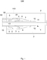
- Fig. 1 shows a high-voltage set 100 for receiving a high-voltage cable 1 according to an exemplary embodiment in a schematic central cross-sectional view along the cylinder axis of the high-voltage cable 1.
- the rotationally symmetrical high-voltage cable 1 contains a conductor 11 on the inside for conducting high-voltage current, for example an aluminum or copper conductor which is made by one Cable insulation 12, typically a XLPE insulation (cross-linked polyethylene), and an outer cable shield 13, for example an outer conductive layer or a semiconductive outer cable shield, is surrounded.
- the high-voltage cable 1 can additionally have cushion layers and a copper screen and an outer jacket for protection against environmental influences. This can be a polyethylene jacket or a jacket made of another halogen-free material.
- the high-voltage cable 1 can be an inner one Have conductive layer between the conductor 11 and the XLPE insulation. This inner conductive layer is also not shown.
- the high-voltage set 100 shown represents a cable end closure 100, as is used, for example, in overhead lines.
- the cable termination 100 has a housing 110, for example a ceramic housing, which seals off the inner parts of the high-voltage fitting 1 from the surroundings.
- An insulation region 2 is arranged in the interior of the housing.
- the insulation region 2 can be formed, for example, by an insulation space filled with oil or gas.
- the isolation region 2 forms an essentially cylinder-symmetrical region.
- the outer layers (cable sheath, cushion layers and metallic shield) are removed, the typically semiconducting outer cable shield 13 continues into the area of the field control part and then only the cable insulation 12 through the end closure up to the head fitting the conductor 11 continued axially. Only the conductor 11 is completely passed through the cable end closure 100 to in the right area of Figure 1 to be connected to the overhead line after leaving the cable end closure 100. In the interior of the cable termination 100, the conductor 11 is directly surrounded by the insulation region 2 only in the area of the removed cable insulation.
- a rotationally symmetrical, electrically isolating field control part 3 is inserted into the isolating area 2, which occupies the space within the isolating area 2 in which the electric field strength would be too large for the isolating materials in the isolating area 2.
- the field control part 3 has an inner hollow cylinder into which the high-voltage cable 1 can be inserted.
- the field control part 3 can be designed as a field control cone.
- the field control part 3 is an elastomeric field control part, which consists of an elastomer body, for example a silicone elastomer body.
- the inner hollow cylinder is typically dimensioned such that there is an interference fit between the cable insulation 12 of the inserted cable 1 and the field control part 3 and the field control part 3 thus forms a stress cone.
- the insulation region 2 and the field control part 3 together form the insulation 2, 3 of the cable termination 100.
- the field control part 3 and / or the high-voltage cable 1 can additionally be fixed, for example by means of springs, to the housing 110 or in a region 5 of the insulation region 2 near the cable, e.g. if the insulation region 2 is formed by a solid insulation body.
- Such a fixation of field control part 3 and / or high-voltage cable 1 is typically used in a construction of the cable termination 100 in a component construction.
- the construction of the cable end closure 100 can also be designed in accordance with the winding technique or slide-on technique.
- the insulation comprises a field control part 3 for receiving the cable 1 with partially removed cable insulation 12 and for appropriately guiding the field lines in high-voltage operation.
- the conductive deflector 4 is in electrical contact with the cable shield 13.
- the conductive deflector 4 also consists of a silicone elastomer, which, however, has a suitable electrical conductivity due to doping. Because of material inhomogeneities or errors, there are typically areas of increased field strength. These are in Fig. 1 represented by the areas 8 with dashed lines. The probability of occurrence or onset of partial discharges is increased in areas 8 with increased field strength.
- a fiber-optic sensor 20 is arranged inside the high-voltage set 100.
- the fiber-optic sensor 20 is completely embedded in the field control part 3, which surrounds the cable insulation 12 of the high-voltage cable 1 and thus its conductor 11 in the area described above.
- the field control part 3 thus represents at least part of an insulation of the high-voltage set 100.
- the fiber-optic sensor 20 is a sensor that can detect a mechanical deformation in an adjacent medium, ie in the field control part 3.
- Optical measurement or test signals can be fed to and removed from the typically passive fiber-optic sensor 20 via one or more optical supply fibers 50. This avoids a galvanic connection between the fiber optic sensor 20 and an evaluation unit.
- Fiber-optic sensors can detect mechanical deformations in a particularly sensitive manner.
- the fiber optic sensor 20 is typically designed to consist only of dielectric materials, e.g. made of glass or polymer material, and therefore the electrical field distribution in the cable termination 100 does not change or changes only insignificantly.
- the fiber optic sensor 20 is practically not influenced by external electromagnetic fields. Therefore, the fiber optic sensor 20 can also be positioned in the vicinity of areas 8 with a particularly high field strength, and therefore in the vicinity of risk areas, for the detection of partial discharges. This enables sensitive monitoring of partial discharges during operation, i.e. under high voltage conditions. This increases the safety of the operation of high-voltage systems.
- the measurement results or the measurement signals can be forwarded to a central monitoring point via one or more optical supply fibers 50, so that complex measurement campaigns on site can be dispensed with. Due to the low fiber attenuation, even fiber-optic measurements from a central monitoring point are possible over long distances.
- the electrical field distribution in the field control part 3 can change.
- the shape and / or conductivity of the conductive deflector 4 can be modified such that the change in the electric field caused by the fiber-optic sensor 20 and / or the optical supply fibers 50 is compensated for.
- the fiber-optic sensor 20 coupled mechanically with the insulation enables a more sensitive detection of deformations and / or vibration of the insulation and thus an earlier detection of partial discharges.
- the fiber optic sensor 20 In addition to the in Fig. 1 illustrated complete embedding of the fiber optic sensor 20, it is also possible to embed the fiber optic sensor 20 only partially in the typically elastomeric field control part 3.
- the arrangement of the fiber-optic sensor 20 within the high-voltage set 100 also protects it from external influences, so that reliable and low-maintenance sensors can be made available for partial discharges.
- the fiber optic sensor 20 is typically a passive sensor that is associated with an optical test signal, e.g. a laser signal is supplied via one of the optical supply fibers 50. These test signals can be provided by a central supply unit for one or more high-voltage sets 100.
- the optical test signals e.g. B. to generate suitable laser pulses in a measuring and evaluation device 60 located in the vicinity of the cable end closure 100, and also to carry out the measurement value acquisition, processing and / or evaluation there.
- the measuring and evaluation device 60 is located outside the high-voltage area, i.e. outside the cable end seal 100 or in the area 5 near the cable, in order not to disturb the electronics of the measuring and evaluation device 60.
- the fiber-optic sensor 20 can be a strain sensor and / or a bending sensor. This makes it possible to demonstrate changes in shape of the field control part 3, which give a clear indication of an impending breakthrough.
- the cable end closure 100 can therefore be changed in good time.
- the fiber-optic sensor 20 can in particular be a sound sensor that detects the sound emissions caused by partial discharges.
- the fiber optic sensor 20 is typically set up in such a way that it can detect mechanical vibrations with frequencies in the range from approximately 10 kHz to approximately 5 MHz, and in particular frequencies in the range from approximately 50 kHz to approximately 500 MHz.
- the fiber-optic sensor 20 is sensitive only in selected subregions or also in relatively narrow selected frequency bands, the subregions thereof frequency bands for given insulation materials and voltages are matched to the sound frequencies to be expected from partial discharges.
- the fiber-optic sensor 20 can typically also detect sound events that are caused by partial discharges in the insulation region 2 or the cable insulation 12.
- the fiber-optic sensor 20 can be set up to measure a change in the phase position, the polarization or the light intensity.
- fiber optic sensor 20 is a fiber tip sensor.
- the fiber tip sensor can consist of only one fiber tip or of several fiber tips. If a fiber tip is embedded in an optically transparent or translucent medium, such as a silicone elastomer as cable insulation, or at least adjoins it, then the light backscattered at the interface between the fiber core and the medium can be used to determine the optical refractive index and thus the density of the adjacent elastomer getting closed. Changes in density and / or oscillations of the elastomer can thus be detected optically via the backscattered light.
- an optically transparent or translucent medium such as a silicone elastomer as cable insulation, or at least adjoins it
- the fiber optic sensor 20 is a phase sensitive sensor, e.g. an interferometric sensor.
- the fiber optic sensor 20 can e.g. a Fabry-Perot interferometer. This enables particularly sensitive measurements to be carried out.
- the fiber-optic sensor 20 can also be a fiber Bragg grating sensor with which in particular lamb waves, ie mixed pressure and shear waves, can be detected.
- the fiber Bragg grating sensor is typically designed in such a way that it can detect irreversible deformations of the field control part 3 and / or sound events. Irreversible deformations of the field control part 3 can be caused by partial electrical discharges, but can also be preceded by partial electrical discharges. For example, it can be used for very large end closures with dimensions of up to a few meters mechanical signs of settlement of the correspondingly heavy components occur. In this way, voltages or deformations of the field control part 3 can be connected, which in turn can promote or initiate partial electrical discharges. With a fiber Bragg grating sensor, structural damage causing electrical partial discharges can also be detected.
- the fiber-optic sensor 20 can, however, also be a quasi-distributed fiber-optic sensor. This consists of a fiber with several measuring points that are at regular intervals from each other. Time-based backscatter measurements can be used to detect irreversible deformations and thus also changes in the field control part 3 causing electrical partial discharges in sections along the fiber in the field control part 3.
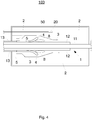
- Fig. 2 shows a high-voltage set 101 for receiving a high-voltage cable 1 according to an exemplary embodiment in a schematic central cross-sectional view along the cylinder axis of the high-voltage cable 1.
- the high-voltage set 101 is similar to the high-voltage set 100 and also represents a cable end closure.
- the fiber optic sensor 20 is on one Surface of the field control part 3 is arranged in the area 5 near the cable, which is at earth potential. There, the fiber optic sensor 20 can also detect a mechanical deformation of the field control part 3.
- the fiber-optic sensor 20 can typically also detect sound events that are caused by partial discharges in the insulating body region 2 or the cable insulation 12.
- Fig. 3 shows a high-voltage set 102 for receiving a high-voltage cable 1 according to an exemplary embodiment in a schematic central cross-sectional view along the cylinder axis of the high-voltage cable 1.
- the high-voltage set 102 is similar to the high-voltage set 100 and also represents a cable end closure.
- the cable end closure 102 has two fiber-optic sensors 20 and 21 for the detection of mechanical deformations and / or vibrations, both of which are embedded in the field control part 3 and connected via respective optical supply fibers 50 and 51.
- the Both fiber-optic sensors 20 and 21 can be sensitive to sound events, for example at different frequencies or on different frequency bands of partial discharges.
- one or more first fiber-optic sensors can be sound-sensitive and one or more second fiber-optic sensors can be set up to measure irreversible deformations. Electrical partial discharges can be detected with the one or more first fiber-optical sensors and structural damage that can precede electrical partial discharges with the one or more second fiber-optical sensors.
- Fig. 4 shows a high-voltage set 103 for receiving a high-voltage cable 1 according to an exemplary embodiment in a schematic central cross-sectional view along the cylinder axis of the high-voltage cable 1.
- the high-voltage set 103 is similar to the high-voltage set 100 and also represents a cable end closure.
- the fiber optic sensor 20 of the cable end closure 103 is not shown in FIG the field control part 3, but arranged in the adjacent isolation area 2.
- the insulation region 2 can be a gas or oil-filled insulation region 2.
- the isolation region 2 can also be a solid insulation body 2, in which the fiber-optic sensor 20 is embedded.
- the fiber-optic sensor 20 in the insulation area 2 can also detect sound events which are caused by partial discharges in the field control part 3 and / or in the cable insulation 12 and / or in the insulation area 2.
- Fig. 5 shows a high-voltage set 200 for receiving two high-voltage cables 1 and 22 according to an exemplary embodiment in a schematic central cross-sectional view along the cylinder axes of the coaxially oriented high-voltage cables 1 and 22.
- the rotationally symmetrical high-voltage cables 1, 22 each comprise a conductor 11 or 112 for conducting high-voltage current and a cable insulation 12, 122 surrounding the respective conductor 11, 112.
- the high-voltage fitting 200 represents a high-voltage cable sleeve for connecting two high-voltage cables.
- the cable sleeve 200 has a housing 210, for example a metal housing, in which the high-voltage cables 1 and 22 are arranged centrally.
- the insulation area 2 of the cable sleeve 200 typically becomes formed by a cast resin insulator or a silicone body. Furthermore, the insulation and field control in the area of the connected metallic conductors 11, 112 must be restored. This is done, for example, via a crimp connection and with a weakly conductive polymer ring 7, which are also embedded in the insulation region 2.
- the typically rotationally symmetrical insulation 2, 3, 32 of the cable sleeve 200 is formed by the field control parts 3, 23 and the insulation region 2.
- the insulation region 2 can be closed off by an outer conductive sleeve coating, not shown, which is arranged on the outer surface of the insulation region 2, a small gap to the housing 210 being able to remain, and which is at ground potential together with the cable shields 13, 132.
- the field control parts 3, 32 are typically elastomeric field control parts 3, 32, in which a respective conductive deflector 4, 42 is integrated.
- the cable sleeve 200 can be designed in component construction, in extrusion technology or in accordance with the winding technology or the push-on technology.
- the insulation of the cable sleeve in component form can consist of a coherent elastomeric field control part with integrated deflectors 4, 42, which occupies the space of the Fig.
- the insulation comprises at least one field control part 3, 32 for receiving the cables 1, 22 with the cable insulation 12, 122 removed at the respective cable ends and for appropriately guiding the field lines in high-voltage operation.
- a fiber optic sensor 20 is as used with respect to FIGS Figures 1 to 4 has been described, arranged in the isolation area 2 or embedded in the isolation area 2.
- the fiber-optic sensor 20 is also one Act sensor that can detect a deformation, in particular an oscillating deformation, for example a vibration of the medium surrounding it. Partial discharges occurring in the insulation of the cable sleeve 200 can thus be reliably detected and simply observed over long periods of time during high-voltage operation.
- the fiber-optic sensor 20 is also embedded in one of the two or in both field control parts 3 and 32, or on a surface of one of the two or both field control parts 3 and 32 in the region 5, 52 in the respective cable near ground potential and on that conductive sleeve coating can be arranged.
- Fig. 6 shows a high-voltage set 201 for receiving two high-voltage cables 1 and 22 according to an embodiment in a schematic central cross-sectional view along the cylinder axes of the coaxially oriented high-voltage cables 1 and 22.
- the high-voltage set 201 is similar to the high-voltage set 200 and also represents a cable sleeve.
- the cable sleeve 201 is however, in each of the two field control parts 3 and 32, a fiber optic sensor 20, 21 is embedded, which is connected via optical supply fibers 50 and 51, respectively.
- the two fiber-optic sensors 20, 21 can also be arranged in the isolation area 2, on a surface of the isolation area 2 and / or on a surface of each of the two field control parts 3 and 32.
- more than two fiber-optic sensors can also be arranged within the cable sleeve 201, which can be used for reliable detection and / or more precise localization of the partial discharge.
- Each of the plurality of fiber optic sensors is typically embedded in the isolation region 2 or in one of the two or both field control parts 3 and 32, or is arranged on a surface of the insulation region 2 and / or one of the two or both field control parts 3 and 32.
- a method for the detection of partial discharges in an insulation of a high voltage set e.g. a cable sleeve or a cable end closure, the measurement of a mechanical size of the insulation by means of a fiber optic sensor.
- the isolation comprises a field control part, e.g. an elastomeric field control part.
- the fiber optic sensor can be arranged on a surface of the field control part and / or can be partially or completely embedded. The fiber-optic sensor is thus typically arranged within the high-voltage set.
- the fiber-optic sensors partially or completely embedded in the insulation or arranged on the surface of the elastomeric field control part typically enable early detection of partial discharges.
- the temporal development of the partial discharge can thus be followed from a very early point in time. This leads to a further improved prognosis of the aging condition of the cable insulation and thus contributes to increased operational safety.
- the measurement of a mechanical quantity typically includes the measurement of a pressure, a voltage, a deformation and / or a vibration in the insulation, e.g. a frequency spectrum and / or a structure-borne sound duration. Due to the characteristic frequency spectrum of sound emissions caused by partial discharges, fiber-optic measurements of the vibration in the insulation allow a particularly reliable conclusion about partial discharges or the associated development of discharge trees and material destruction.
- the mechanical size is typically measured in the current-carrying state of the high-voltage set during operation. This also enables a continuous or event-dependent measurement of the mechanical size, ie monitoring of partial discharges during operation. As a result, the security of a high-voltage network and / or a high-voltage device, the high-voltage fittings of which are monitored with integrated fiber-optic sensors, can be significantly improved.
- the mechanical quantities measured on the individual high-voltage sets of a high-voltage system or a high-voltage network are transmitted via an online connection, e.g. transmitted via a fiber optic network to a central evaluation unit or control unit, which takes over the monitoring. This will typically issue a corresponding warning message immediately upon detection of partial discharge activities. This means that the endangered high-voltage set can be replaced in good time before an impending breakthrough.
- the fiber optic sensors can share a common data line, e.g. share an optical data line in order to communicate with the central evaluation unit.
- a fiber optic network can also be a central light source, e.g. a laser, glass fibers that guide the light to the individual passive fiber-optic sensors, and a further set of fibers that guide the optionally modulated light to a common photodetector in the central evaluation unit. Communication between the fiber optic sensors and the central evaluation unit can also take place via an optical multiplexer.
- a fiber optic measuring system comprises a central evaluation unit, a light source, typically a laser, a detection unit with at least one photo sensor, one or more passive fiber-optic sensors that can detect a mechanical size and are mechanically coupled to a respective insulation of a high-voltage set, as well as fiber-optic lines, that connect the one or more passive fiber optic sensors to the light source and the detection unit.
- the detection unit can represent part of the central evaluation unit.
- the central evaluation unit is set up to detect and / or characterize a partial discharge in an insulation by evaluating the measurements of mechanical variables by means of the one or more fiber-optic sensors and to issue corresponding warning messages. This makes it possible to provide a simple monitoring system for partial discharges in high-voltage sets, which allows continuous monitoring during high-voltage operation of the high-voltage sets and thus increases their safety.
Landscapes
- Physics & Mathematics (AREA)
- General Physics & Mathematics (AREA)
- Testing Relating To Insulation (AREA)
Priority Applications (1)
| Application Number | Priority Date | Filing Date | Title |
|---|---|---|---|
| PL11192360T PL2472689T3 (pl) | 2010-12-28 | 2011-12-07 | Zespół wysokiego napięcia i sposób wykrywania niezupełnych wyładowań w zespołach wysokiego napięcia |
Applications Claiming Priority (1)
| Application Number | Priority Date | Filing Date | Title |
|---|---|---|---|
| DE102010061606.0A DE102010061606B4 (de) | 2010-12-28 | 2010-12-28 | Hochspannungsgarnitur und Verfahren zur Detektion von Teilentladungen in Hochspannungsgarnituren |
Publications (3)
| Publication Number | Publication Date |
|---|---|
| EP2472689A2 EP2472689A2 (de) | 2012-07-04 |
| EP2472689A3 EP2472689A3 (de) | 2014-05-07 |
| EP2472689B1 true EP2472689B1 (de) | 2020-03-11 |
Family
ID=45463225
Family Applications (1)
| Application Number | Title | Priority Date | Filing Date |
|---|---|---|---|
| EP11192360.3A Active EP2472689B1 (de) | 2010-12-28 | 2011-12-07 | Hochspannungsgarnitur und Verfahren zur Detektion von Teilentladungen in Hochspannungsgarnituren |
Country Status (5)
| Country | Link |
|---|---|
| EP (1) | EP2472689B1 (da) |
| DE (1) | DE102010061606B4 (da) |
| DK (1) | DK2472689T3 (da) |
| ES (1) | ES2796248T3 (da) |
| PL (1) | PL2472689T3 (da) |
Families Citing this family (8)
| Publication number | Priority date | Publication date | Assignee | Title |
|---|---|---|---|---|
| GB2531325A (en) * | 2014-10-16 | 2016-04-20 | Repl Internat Ltd | Medium-Voltage cable joint |
| EP3223024B1 (en) * | 2016-03-23 | 2018-11-14 | 3M Innovative Properties Company | Elastic sleeve for a power conductor |
| DE102018003744A1 (de) | 2018-05-07 | 2019-11-07 | Senvion Gmbh | Akustisches Zustandsüberwachungsverfahren und -system für elektrische Leistungskomponenten, insbesondere Transformatoren |
| EP3644074B1 (en) * | 2018-10-26 | 2026-04-08 | Tyco Electronics Raychem GmbH | Optical detector for a high-voltage cable accessory and method of optically measuring electrical discharges |
| CN109725242B (zh) * | 2019-03-14 | 2024-06-25 | 深圳供电局有限公司 | 单芯电缆局部放电传感器及局部放电传感器阵列 |
| CN109709461B (zh) * | 2019-03-14 | 2024-08-20 | 深圳供电局有限公司 | 局部放电检测系统 |
| DE102020119012B4 (de) | 2020-07-17 | 2022-05-19 | Hochschule Für Technik Und Wirtschaft Berlin | Vorrichtung und Verfahren zum Bestimmen einer Ladungsstärke einer Teilentladung |
| CN113325283B (zh) * | 2021-05-26 | 2024-06-07 | 许继集团有限公司 | 一种充气柜绝缘试验用装置 |
Citations (3)
| Publication number | Priority date | Publication date | Assignee | Title |
|---|---|---|---|---|
| FR2397732A1 (fr) * | 1977-07-16 | 1979-02-09 | Kabel & Lackdrahtfab Gmbh | Boite d'extremite |
| WO1997009762A1 (en) * | 1995-09-05 | 1997-03-13 | Asea Brown Boveri Ab | Cable termination |
| US20050134837A1 (en) * | 2003-12-23 | 2005-06-23 | Sarkozi Janos G. | Detection of partial discharge or arcing in wiring via fiber optics |
Family Cites Families (8)
| Publication number | Priority date | Publication date | Assignee | Title |
|---|---|---|---|---|
| DE1490580A1 (de) * | 1964-05-22 | 1969-07-10 | Sueddeutsche Telefon App Kabel | Verbindungsmuffe fuer Hochspannungskunststoffkabel |
| DE3822288A1 (de) | 1988-07-01 | 1990-01-04 | Felten & Guilleaume Energie | Verbindungsmuffe fuer vpe-isolierte hoechstspannungskabel |
| JPH02269980A (ja) * | 1989-04-12 | 1990-11-05 | Furukawa Electric Co Ltd:The | 電力ケーブル又はその接続部の異常検出装置 |
| JPH087250B2 (ja) * | 1989-07-31 | 1996-01-29 | 三井石油化学工業株式会社 | 電気設備の絶縁劣化監視装置 |
| DE19514852C2 (de) * | 1995-04-26 | 1997-07-03 | Deutsche Forsch Luft Raumfahrt | Verfahren und Anordnung zur Beschleunigungs- und Vibrationsmessung |
| US6300767B1 (en) | 1998-11-30 | 2001-10-09 | General Electric Company | System and apparatus for predicting failure in insulated systems |
| GB0517994D0 (en) * | 2005-09-05 | 2005-10-12 | Univ Glasgow | High voltage insulation monitoring sensor |
| DE102009007142A1 (de) * | 2009-02-02 | 2010-08-05 | Draka Industrial Cable Gmbh | Faseroptische Messvorrichtung |
-
2010
- 2010-12-28 DE DE102010061606.0A patent/DE102010061606B4/de not_active Expired - Fee Related
-
2011
- 2011-12-07 DK DK11192360.3T patent/DK2472689T3/da active
- 2011-12-07 PL PL11192360T patent/PL2472689T3/pl unknown
- 2011-12-07 EP EP11192360.3A patent/EP2472689B1/de active Active
- 2011-12-07 ES ES11192360T patent/ES2796248T3/es active Active
Patent Citations (3)
| Publication number | Priority date | Publication date | Assignee | Title |
|---|---|---|---|---|
| FR2397732A1 (fr) * | 1977-07-16 | 1979-02-09 | Kabel & Lackdrahtfab Gmbh | Boite d'extremite |
| WO1997009762A1 (en) * | 1995-09-05 | 1997-03-13 | Asea Brown Boveri Ab | Cable termination |
| US20050134837A1 (en) * | 2003-12-23 | 2005-06-23 | Sarkozi Janos G. | Detection of partial discharge or arcing in wiring via fiber optics |
Non-Patent Citations (1)
| Title |
|---|
| BANJI ET AL: "Electroluminescence - a technique to detect the initiation of degradation in polymeric insulation", 19990601; 19990600, vol. 15, no. 3, 1 June 1999 (1999-06-01), pages 9 - 14, XP011084569 * |
Also Published As
| Publication number | Publication date |
|---|---|
| DK2472689T3 (da) | 2020-06-15 |
| ES2796248T3 (es) | 2020-11-26 |
| DE102010061606B4 (de) | 2018-12-27 |
| EP2472689A3 (de) | 2014-05-07 |
| PL2472689T3 (pl) | 2020-08-10 |
| DE102010061606A1 (de) | 2012-06-28 |
| EP2472689A2 (de) | 2012-07-04 |
Similar Documents
| Publication | Publication Date | Title |
|---|---|---|
| EP2472688B1 (de) | Hochspannungseinrichtung und Verfahren zum Monitoring von Alterungsprozessen einer Isolierung in einer Hochspannungseinrichtung | |
| DE102010061606B4 (de) | Hochspannungsgarnitur und Verfahren zur Detektion von Teilentladungen in Hochspannungsgarnituren | |
| DE102018130830B3 (de) | Prüfvorrichtung zum Erfassen eines Isolationswiderstands einer Hochvoltleitung sowie zugehöriges Prüfverfahren | |
| EP3295530B1 (de) | Hochspannungskabelgarnitur und verfahren zum herstellen einer hochspannungskabelgarnitur | |
| DE69925929T2 (de) | Verfahren zur diagnose von isolationsverschlechterungen in unterirdischen kabeln | |
| EP1240704A1 (de) | Optische messeinrichtung in einem eingepressten leiterstab einer elektrischen maschine | |
| DE102010061605A1 (de) | Faseroptischer Sensor sowie Messeinrichtung mit einem faseroptischen Sensor | |
| EP3729032B1 (de) | Elektrischer stecker mit einem temperatursensor | |
| DE102018103901A1 (de) | Verfahren zum Bestimmen eines Betriebszustands eines elektrischen Betriebsmittels und Anordnung | |
| EP3499253A1 (de) | Seekabelstrecke und verfahren zur ermittlung einer elektrischen teilentladung in einer seekabelstrecke | |
| EP2930522A1 (de) | Verfahren sowie vorrichtung zur ortsaufgelösten diagnose | |
| CH717001A2 (de) | Verfahren zur Überwachung eines flüssigkeitsgekühlten Ladekabels einer Ladestation für eine Traktionsbatterie eines elektrisch betriebenen Kraftfahrzeugs. | |
| EP2863236B1 (de) | Prüfsystem für Hochspannungskomponenten | |
| EP2466286A1 (de) | Faseroptisches Wassermeldesystem | |
| DE102019116233B4 (de) | Zustandsüberwachung von Überspannungsschutzkomponenten | |
| DE102013104155B4 (de) | Hochspannungseinrichtung mit einem faseroptischen Sensor und Verfahren zum Prüfen einer Isolierung einer derartigen Hochspannungseinrichtung | |
| DE69925946T2 (de) | Gerät und Verfahren zur Erfassung von Fehlern eines Kabelisolierungsmantels und Anlagen die sie benutzen | |
| DE102015101608A1 (de) | Verfahren zur Signalweiterleitung und Vorrichtung mit einer optischen Faser | |
| DE102017212476B4 (de) | Kabel mit Mantelanordnung zur Biegungserkennung, Anordnung zur Messung einer Biegung eines Kabels und Verfahren zur Messung einer Biegung eines Kabels | |
| DE102018127444A1 (de) | Verfahren zur elektrischen Messung des mechanischen Verschleißzustandes von elektrischen Leitungen, insbesondere von isolierten elektrischen Leitern, sowie Vorrichtung zur Durchführung eines solchen Verfahrens | |
| DE19515068A1 (de) | Anordnung zur TE-Detektion in Hochspannungskabeln und in deren Verbindungselementen | |
| DE102018103258A1 (de) | Ultraschallprüfvorrichtung und Verfahren zur Herstellung eines Ultraschallprüfkopfs für eine derartige Ultraschallprüfvorrichtung | |
| DE102010013103B4 (de) | Vorrichtung und Verfahren zur Diagnose von Messobjekten unter Verwendung einer Messspannung | |
| Hussain et al. | Detection of multiple partial discharge faults in switchgear and power cables | |
| Esterl et al. | Electrical treeing and partial discharges in DC-XLPE under constant DC voltage and repetitive DC ramp voltage |
Legal Events
| Date | Code | Title | Description |
|---|---|---|---|
| AK | Designated contracting states |
Kind code of ref document: A2 Designated state(s): AL AT BE BG CH CY CZ DE DK EE ES FI FR GB GR HR HU IE IS IT LI LT LU LV MC MK MT NL NO PL PT RO RS SE SI SK SM TR |
|
| AX | Request for extension of the european patent |
Extension state: BA ME |
|
| PUAI | Public reference made under article 153(3) epc to a published international application that has entered the european phase |
Free format text: ORIGINAL CODE: 0009012 |
|
| PUAL | Search report despatched |
Free format text: ORIGINAL CODE: 0009013 |
|
| AK | Designated contracting states |
Kind code of ref document: A3 Designated state(s): AL AT BE BG CH CY CZ DE DK EE ES FI FR GB GR HR HU IE IS IT LI LT LU LV MC MK MT NL NO PL PT RO RS SE SI SK SM TR |
|
| AX | Request for extension of the european patent |
Extension state: BA ME |
|
| RIC1 | Information provided on ipc code assigned before grant |
Ipc: G01R 31/14 20060101ALI20140331BHEP Ipc: H02G 15/103 20060101AFI20140331BHEP Ipc: G01D 5/353 20060101ALI20140331BHEP Ipc: G01D 5/26 20060101ALI20140331BHEP Ipc: G01R 31/12 20060101ALI20140331BHEP |
|
| 17P | Request for examination filed |
Effective date: 20141016 |
|
| RBV | Designated contracting states (corrected) |
Designated state(s): AL AT BE BG CH CY CZ DE DK EE ES FI FR GB GR HR HU IE IS IT LI LT LU LV MC MK MT NL NO PL PT RO RS SE SI SK SM TR |
|
| 17Q | First examination report despatched |
Effective date: 20150226 |
|
| STAA | Information on the status of an ep patent application or granted ep patent |
Free format text: STATUS: EXAMINATION IS IN PROGRESS |
|
| GRAP | Despatch of communication of intention to grant a patent |
Free format text: ORIGINAL CODE: EPIDOSNIGR1 |
|
| STAA | Information on the status of an ep patent application or granted ep patent |
Free format text: STATUS: GRANT OF PATENT IS INTENDED |
|
| INTG | Intention to grant announced |
Effective date: 20191002 |
|
| GRAS | Grant fee paid |
Free format text: ORIGINAL CODE: EPIDOSNIGR3 |
|
| GRAA | (expected) grant |
Free format text: ORIGINAL CODE: 0009210 |
|
| STAA | Information on the status of an ep patent application or granted ep patent |
Free format text: STATUS: THE PATENT HAS BEEN GRANTED |
|
| AK | Designated contracting states |
Kind code of ref document: B1 Designated state(s): AL AT BE BG CH CY CZ DE DK EE ES FI FR GB GR HR HU IE IS IT LI LT LU LV MC MK MT NL NO PL PT RO RS SE SI SK SM TR |
|
| REG | Reference to a national code |
Ref country code: GB Ref legal event code: FG4D Free format text: NOT ENGLISH |
|
| REG | Reference to a national code |
Ref country code: CH Ref legal event code: EP |
|
| REG | Reference to a national code |
Ref country code: AT Ref legal event code: REF Ref document number: 1244358 Country of ref document: AT Kind code of ref document: T Effective date: 20200315 |
|
| REG | Reference to a national code |
Ref country code: IE Ref legal event code: FG4D Free format text: LANGUAGE OF EP DOCUMENT: GERMAN |
|
| REG | Reference to a national code |
Ref country code: DE Ref legal event code: R096 Ref document number: 502011016531 Country of ref document: DE |
|
| REG | Reference to a national code |
Ref country code: DK Ref legal event code: T3 Effective date: 20200609 |
|
| REG | Reference to a national code |
Ref country code: NL Ref legal event code: FP |
|
| REG | Reference to a national code |
Ref country code: SE Ref legal event code: TRGR |
|
| PG25 | Lapsed in a contracting state [announced via postgrant information from national office to epo] |
Ref country code: RS Free format text: LAPSE BECAUSE OF FAILURE TO SUBMIT A TRANSLATION OF THE DESCRIPTION OR TO PAY THE FEE WITHIN THE PRESCRIBED TIME-LIMIT Effective date: 20200311 Ref country code: FI Free format text: LAPSE BECAUSE OF FAILURE TO SUBMIT A TRANSLATION OF THE DESCRIPTION OR TO PAY THE FEE WITHIN THE PRESCRIBED TIME-LIMIT Effective date: 20200311 |
|
| REG | Reference to a national code |
Ref country code: NO Ref legal event code: T2 Effective date: 20200311 |
|
| PG25 | Lapsed in a contracting state [announced via postgrant information from national office to epo] |
Ref country code: LV Free format text: LAPSE BECAUSE OF FAILURE TO SUBMIT A TRANSLATION OF THE DESCRIPTION OR TO PAY THE FEE WITHIN THE PRESCRIBED TIME-LIMIT Effective date: 20200311 Ref country code: HR Free format text: LAPSE BECAUSE OF FAILURE TO SUBMIT A TRANSLATION OF THE DESCRIPTION OR TO PAY THE FEE WITHIN THE PRESCRIBED TIME-LIMIT Effective date: 20200311 Ref country code: GR Free format text: LAPSE BECAUSE OF FAILURE TO SUBMIT A TRANSLATION OF THE DESCRIPTION OR TO PAY THE FEE WITHIN THE PRESCRIBED TIME-LIMIT Effective date: 20200612 Ref country code: BG Free format text: LAPSE BECAUSE OF FAILURE TO SUBMIT A TRANSLATION OF THE DESCRIPTION OR TO PAY THE FEE WITHIN THE PRESCRIBED TIME-LIMIT Effective date: 20200611 |
|
| REG | Reference to a national code |
Ref country code: LT Ref legal event code: MG4D |
|
| PG25 | Lapsed in a contracting state [announced via postgrant information from national office to epo] |
Ref country code: IS Free format text: LAPSE BECAUSE OF FAILURE TO SUBMIT A TRANSLATION OF THE DESCRIPTION OR TO PAY THE FEE WITHIN THE PRESCRIBED TIME-LIMIT Effective date: 20200711 Ref country code: PT Free format text: LAPSE BECAUSE OF FAILURE TO SUBMIT A TRANSLATION OF THE DESCRIPTION OR TO PAY THE FEE WITHIN THE PRESCRIBED TIME-LIMIT Effective date: 20200805 Ref country code: EE Free format text: LAPSE BECAUSE OF FAILURE TO SUBMIT A TRANSLATION OF THE DESCRIPTION OR TO PAY THE FEE WITHIN THE PRESCRIBED TIME-LIMIT Effective date: 20200311 Ref country code: SM Free format text: LAPSE BECAUSE OF FAILURE TO SUBMIT A TRANSLATION OF THE DESCRIPTION OR TO PAY THE FEE WITHIN THE PRESCRIBED TIME-LIMIT Effective date: 20200311 Ref country code: SK Free format text: LAPSE BECAUSE OF FAILURE TO SUBMIT A TRANSLATION OF THE DESCRIPTION OR TO PAY THE FEE WITHIN THE PRESCRIBED TIME-LIMIT Effective date: 20200311 Ref country code: CZ Free format text: LAPSE BECAUSE OF FAILURE TO SUBMIT A TRANSLATION OF THE DESCRIPTION OR TO PAY THE FEE WITHIN THE PRESCRIBED TIME-LIMIT Effective date: 20200311 Ref country code: RO Free format text: LAPSE BECAUSE OF FAILURE TO SUBMIT A TRANSLATION OF THE DESCRIPTION OR TO PAY THE FEE WITHIN THE PRESCRIBED TIME-LIMIT Effective date: 20200311 Ref country code: LT Free format text: LAPSE BECAUSE OF FAILURE TO SUBMIT A TRANSLATION OF THE DESCRIPTION OR TO PAY THE FEE WITHIN THE PRESCRIBED TIME-LIMIT Effective date: 20200311 |
|
| REG | Reference to a national code |
Ref country code: ES Ref legal event code: FG2A Ref document number: 2796248 Country of ref document: ES Kind code of ref document: T3 Effective date: 20201126 |
|
| REG | Reference to a national code |
Ref country code: DE Ref legal event code: R097 Ref document number: 502011016531 Country of ref document: DE |
|
| PLBE | No opposition filed within time limit |
Free format text: ORIGINAL CODE: 0009261 |
|
| STAA | Information on the status of an ep patent application or granted ep patent |
Free format text: STATUS: NO OPPOSITION FILED WITHIN TIME LIMIT |
|
| 26N | No opposition filed |
Effective date: 20201214 |
|
| PG25 | Lapsed in a contracting state [announced via postgrant information from national office to epo] |
Ref country code: SI Free format text: LAPSE BECAUSE OF FAILURE TO SUBMIT A TRANSLATION OF THE DESCRIPTION OR TO PAY THE FEE WITHIN THE PRESCRIBED TIME-LIMIT Effective date: 20200311 |
|
| REG | Reference to a national code |
Ref country code: NO Ref legal event code: MMEP |
|
| REG | Reference to a national code |
Ref country code: CH Ref legal event code: PL |
|
| REG | Reference to a national code |
Ref country code: SE Ref legal event code: EUG |
|
| REG | Reference to a national code |
Ref country code: NL Ref legal event code: MM Effective date: 20210101 |
|
| GBPC | Gb: european patent ceased through non-payment of renewal fee |
Effective date: 20201207 |
|
| PG25 | Lapsed in a contracting state [announced via postgrant information from national office to epo] |
Ref country code: MC Free format text: LAPSE BECAUSE OF FAILURE TO SUBMIT A TRANSLATION OF THE DESCRIPTION OR TO PAY THE FEE WITHIN THE PRESCRIBED TIME-LIMIT Effective date: 20200311 |
|
| REG | Reference to a national code |
Ref country code: BE Ref legal event code: MM Effective date: 20201231 |
|
| PG25 | Lapsed in a contracting state [announced via postgrant information from national office to epo] |
Ref country code: NL Free format text: LAPSE BECAUSE OF NON-PAYMENT OF DUE FEES Effective date: 20210101 |
|
| REG | Reference to a national code |
Ref country code: DE Ref legal event code: R081 Ref document number: 502011016531 Country of ref document: DE Owner name: IPH INSTITUT "PRUEFFELD FUER ELEKTRISCHE HOCHL, DE Free format text: FORMER OWNERS: BUNDESANSTALT FUER MATERIALFORSCHUNG UND -PRUEFUNG (BAM), 12205 BERLIN, DE; IPH INSTITUT "PRUEFFELD FUER ELEKTRISCHE HOCHLEISTUNGSTECHNIK" GMBH, 12681 BERLIN, DE Ref country code: DE Ref legal event code: R082 Ref document number: 502011016531 Country of ref document: DE Representative=s name: MUELLER, WOLFRAM, DIPL.-PHYS. DR. JUR., DE Ref country code: DE Ref legal event code: R082 Ref document number: 502011016531 Country of ref document: DE Representative=s name: MUELLER, WOLFRAM H., DIPL.-PHYS. DR. JUR., DE |
|
| PG25 | Lapsed in a contracting state [announced via postgrant information from national office to epo] |
Ref country code: LU Free format text: LAPSE BECAUSE OF NON-PAYMENT OF DUE FEES Effective date: 20201207 Ref country code: IE Free format text: LAPSE BECAUSE OF NON-PAYMENT OF DUE FEES Effective date: 20201207 |
|
| PG25 | Lapsed in a contracting state [announced via postgrant information from national office to epo] |
Ref country code: CH Free format text: LAPSE BECAUSE OF NON-PAYMENT OF DUE FEES Effective date: 20201231 Ref country code: GB Free format text: LAPSE BECAUSE OF NON-PAYMENT OF DUE FEES Effective date: 20201207 Ref country code: NO Free format text: LAPSE BECAUSE OF NON-PAYMENT OF DUE FEES Effective date: 20201231 Ref country code: LI Free format text: LAPSE BECAUSE OF NON-PAYMENT OF DUE FEES Effective date: 20201231 Ref country code: SE Free format text: LAPSE BECAUSE OF NON-PAYMENT OF DUE FEES Effective date: 20201208 |
|
| REG | Reference to a national code |
Ref country code: ES Ref legal event code: FD2A Effective date: 20220214 |
|
| REG | Reference to a national code |
Ref country code: AT Ref legal event code: MM01 Ref document number: 1244358 Country of ref document: AT Kind code of ref document: T Effective date: 20201207 |
|
| PG25 | Lapsed in a contracting state [announced via postgrant information from national office to epo] |
Ref country code: AT Free format text: LAPSE BECAUSE OF NON-PAYMENT OF DUE FEES Effective date: 20201207 |
|
| PG25 | Lapsed in a contracting state [announced via postgrant information from national office to epo] |
Ref country code: MT Free format text: LAPSE BECAUSE OF FAILURE TO SUBMIT A TRANSLATION OF THE DESCRIPTION OR TO PAY THE FEE WITHIN THE PRESCRIBED TIME-LIMIT Effective date: 20200311 Ref country code: ES Free format text: LAPSE BECAUSE OF NON-PAYMENT OF DUE FEES Effective date: 20201208 Ref country code: CY Free format text: LAPSE BECAUSE OF FAILURE TO SUBMIT A TRANSLATION OF THE DESCRIPTION OR TO PAY THE FEE WITHIN THE PRESCRIBED TIME-LIMIT Effective date: 20200311 |
|
| PG25 | Lapsed in a contracting state [announced via postgrant information from national office to epo] |
Ref country code: MK Free format text: LAPSE BECAUSE OF FAILURE TO SUBMIT A TRANSLATION OF THE DESCRIPTION OR TO PAY THE FEE WITHIN THE PRESCRIBED TIME-LIMIT Effective date: 20200311 Ref country code: AL Free format text: LAPSE BECAUSE OF FAILURE TO SUBMIT A TRANSLATION OF THE DESCRIPTION OR TO PAY THE FEE WITHIN THE PRESCRIBED TIME-LIMIT Effective date: 20200311 |
|
| PG25 | Lapsed in a contracting state [announced via postgrant information from national office to epo] |
Ref country code: BE Free format text: LAPSE BECAUSE OF NON-PAYMENT OF DUE FEES Effective date: 20201231 |
|
| PG25 | Lapsed in a contracting state [announced via postgrant information from national office to epo] |
Ref country code: PL Free format text: LAPSE BECAUSE OF NON-PAYMENT OF DUE FEES Effective date: 20201207 |
|
| PGFP | Annual fee paid to national office [announced via postgrant information from national office to epo] |
Ref country code: FR Payment date: 20221219 Year of fee payment: 12 Ref country code: DK Payment date: 20221221 Year of fee payment: 12 Ref country code: DE Payment date: 20221024 Year of fee payment: 12 |
|
| PGFP | Annual fee paid to national office [announced via postgrant information from national office to epo] |
Ref country code: IT Payment date: 20221230 Year of fee payment: 12 |
|
| REG | Reference to a national code |
Ref country code: DE Ref legal event code: R119 Ref document number: 502011016531 Country of ref document: DE |
|
| REG | Reference to a national code |
Ref country code: DK Ref legal event code: EBP Effective date: 20231231 |
|
| PG25 | Lapsed in a contracting state [announced via postgrant information from national office to epo] |
Ref country code: TR Free format text: LAPSE BECAUSE OF NON-PAYMENT OF DUE FEES Effective date: 20201207 |
|
| PG25 | Lapsed in a contracting state [announced via postgrant information from national office to epo] |
Ref country code: DE Free format text: LAPSE BECAUSE OF NON-PAYMENT OF DUE FEES Effective date: 20240702 |
|
| PG25 | Lapsed in a contracting state [announced via postgrant information from national office to epo] |
Ref country code: FR Free format text: LAPSE BECAUSE OF NON-PAYMENT OF DUE FEES Effective date: 20231231 |
|
| PG25 | Lapsed in a contracting state [announced via postgrant information from national office to epo] |
Ref country code: FR Free format text: LAPSE BECAUSE OF NON-PAYMENT OF DUE FEES Effective date: 20231231 Ref country code: DE Free format text: LAPSE BECAUSE OF NON-PAYMENT OF DUE FEES Effective date: 20240702 |
|
| PG25 | Lapsed in a contracting state [announced via postgrant information from national office to epo] |
Ref country code: DK Free format text: LAPSE BECAUSE OF NON-PAYMENT OF DUE FEES Effective date: 20231231 |
|
| PG25 | Lapsed in a contracting state [announced via postgrant information from national office to epo] |
Ref country code: DK Free format text: LAPSE BECAUSE OF NON-PAYMENT OF DUE FEES Effective date: 20231231 |
|
| PG25 | Lapsed in a contracting state [announced via postgrant information from national office to epo] |
Ref country code: IT Free format text: LAPSE BECAUSE OF NON-PAYMENT OF DUE FEES Effective date: 20231207 |
|
| PG25 | Lapsed in a contracting state [announced via postgrant information from national office to epo] |
Ref country code: IS Free format text: LAPSE BECAUSE OF NON-PAYMENT OF DUE FEES Effective date: 20200711 |