EP2472801A1 - Adaptives Antennensystem für die Diversitäts- und Interferenzverhinderung in einem Mehrstationsnetzwerk - Google Patents
Adaptives Antennensystem für die Diversitäts- und Interferenzverhinderung in einem Mehrstationsnetzwerk Download PDFInfo
- Publication number
- EP2472801A1 EP2472801A1 EP12161497A EP12161497A EP2472801A1 EP 2472801 A1 EP2472801 A1 EP 2472801A1 EP 12161497 A EP12161497 A EP 12161497A EP 12161497 A EP12161497 A EP 12161497A EP 2472801 A1 EP2472801 A1 EP 2472801A1
- Authority
- EP
- European Patent Office
- Prior art keywords
- stations
- station
- network
- level
- transmitters
- Prior art date
- Legal status (The legal status is an assumption and is not a legal conclusion. Google has not performed a legal analysis and makes no representation as to the accuracy of the status listed.)
- Granted
Links
Images








Classifications
-
- H—ELECTRICITY
- H04—ELECTRIC COMMUNICATION TECHNIQUE
- H04W—WIRELESS COMMUNICATION NETWORKS
- H04W16/00—Network planning, e.g. coverage or traffic planning tools; Network deployment, e.g. resource partitioning or cells structures
- H04W16/24—Cell structures
- H04W16/28—Cell structures using beam steering
-
- H—ELECTRICITY
- H04—ELECTRIC COMMUNICATION TECHNIQUE
- H04W—WIRELESS COMMUNICATION NETWORKS
- H04W16/00—Network planning, e.g. coverage or traffic planning tools; Network deployment, e.g. resource partitioning or cells structures
- H04W16/24—Cell structures
- H04W16/32—Hierarchical cell structures
-
- H—ELECTRICITY
- H04—ELECTRIC COMMUNICATION TECHNIQUE
- H04W—WIRELESS COMMUNICATION NETWORKS
- H04W48/00—Access restriction; Network selection; Access point selection
- H04W48/08—Access restriction or access information delivery, e.g. discovery data delivery
- H04W48/12—Access restriction or access information delivery, e.g. discovery data delivery using downlink control channel
-
- H—ELECTRICITY
- H04—ELECTRIC COMMUNICATION TECHNIQUE
- H04W—WIRELESS COMMUNICATION NETWORKS
- H04W84/00—Network topologies
- H04W84/02—Hierarchically pre-organised networks, e.g. paging networks, cellular networks, WLAN [Wireless Local Area Network] or WLL [Wireless Local Loop]
- H04W84/10—Small scale networks; Flat hierarchical networks
- H04W84/12—WLAN [Wireless Local Area Networks]
Definitions
- THIS invention relates to a method of operating a multi-station communication network, and to a network as such, of the general kind described in International patent applications nos. WO 96/19887 and WO 98/56140 .
- Networks of this kind can be utilized commercially, with users being subscribers who are billed for their use of the network.
- networks of this kind may be utilized by security forces such as police or military forces.
- a further application for networks of the kind referred to is in Wireless Local Area Networks (WLANs), where a wireless network can be combined with conventional network structures to service fixed and mobile network users.
- WLANs Wireless Local Area Networks
- Such networks are usually, but not necessarily, computer networks.
- the functionality of the network can be compromised by factors such as path loss, the lack of signal penetration, the insufficiency of stations available to serve as intermediary stations and the abundance of various sources of interference.
- a method of operating a communication network comprising a plurality of wireless stations, each station being able to transmit and receive data so that the network can transmit a message comprising a plurality of data packets from an originating station to a destination station via at least one intermediate station, wherein at least some stations have a controllable antenna system operable to direct a null selectively, the method including the steps of:
- a null is directed towards a source of interference where the level of the interference exceeds a predetermined level.
- the predetermined level of interference corresponds to the ambient noise floor on said probing channel.
- the method may include operating an antenna system at one or more stations to steer the radiation pattern of the antenna system in order to direct one or more nulls towards the sources of interference, thereby affecting connectivity of neighbouring stations and introducing diversity into the connectivity options available to the stations.
- a source of interference may be a neighbor station, said each station directing a null towards the neighbor station to reduce or eliminate mutual interference.
- two or more neighbor stations may direct nulls toward each other.
- Stations with controllable antennas may direct beams selectively, the method including mapping, at each such station, the location of other stations to a particular beam or beams for ongoing communication.
- Stations with controllable antennas may monitor said one or more probing channels for noise or interference, the method including mapping, at each such station, the location of other stations to a particular beam or beams determined to provide relatively noise or interference free communication to said other stations.
- the method may include storing data relating to the mapped locations at each station, and transmitting the data to other stations in probe signals.
- a station transmitting a probe signal or data to another station selects a beam previously determined to be interference or noise free.
- a communication network comprising a plurality of wireless stations, each station being able to transmit and receive data so that the network can transmit a message comprising a plurality of data packets from an originating station to a destination station via at least one intermediate station, wherein at least some stations have a controllable antenna system operable to direct a null selectively, and wherein each such station is operable to:
- the present invention relates, broadly, to a method of operating a multi-station communication network of the kind described in International patent applications nos. WO 96/19887 and WO 98/56140 , the contents of which are incorporated herein by reference.
- Networks of this kind use opportunistic relaying techniques to transmit message data from source to destination stations, utilising intermediate stations as relays when required, and are referred to herein as ODMA networks, for Opportunity Driven Multiple Access.
- ODMA opportunistic relaying techniques
- the ODMA methodology can be applied to both wireless (typically radio) and wired communication media. The basic operation of such a network is described in Appendix A.
- the path conditions and background noise at each heighbor station are dynamically determined from the probing processes and the combination of slow probe and fast probe mechanisms means that any sending station only needs to ascertain that certain of the neighbors have a lower cost to destination than the station wishing to send data.
- the averaged variations in connectivity between a source and destination station over time are determined through the probed cost information, but an RTS/CTS cycle is used to determine the exact fluctuations experienced between a sending station and a neighbor at the moment of any transmission. From these interactions, a decision is made opportunistically at the moment before the data is sent - packet by packet - in respect of the best connectivity to the neighbor.
- RTS/CTS data transport protocols used in relation to ODMA are described in International Patent applications PCT/IB2004/004109 , PCT/IB2004/004111 , PCT/IB2005/003141 and PCT/IB2007/054966 .
- messages are broken into packets at the sending station.
- a station with a packet to send broadcasts a Request to Send message (RTS).
- RTS Request to Send message
- Neighboring stations that are available and are closer (gradient-wise) to the destination transmit back a Clear to Send message (CTS); and possibly a Ready to Receive message (RTR) for multi-channel systems.
- CTS Clear to Send message
- RTR Ready to Receive message
- the receiving station may transmit a Packet Acknowledge message (ACK) back to the transmitting station.
- ACK Packet Acknowledge message
- the destination station all packets are collected and re-assembled into the message.
- an End-to-End Acknowledge message (End-to-End ACK) may be transmitted back to the message originating station.
- ODMA transmissions may be sent at "peaks of opportunity" in connectivity. This means ODMA is able to take advantage of the very best connectivity conditions that may be available at any given moment (even if these preferable conditions are only fleetingly available) and the path taken is not committed to a single route.
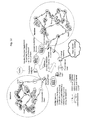
- Figure 2 illustrates a cluttered environment problem in a WLAN environment.
- a station S1 is readily able to transmit a message to a destination station D1; having multiple neighbor stations available to serve as intermediaries at each node in the route as is indicated in the figure (through hops a1 and a2).
- a station S2 wishes to send a message to destination D2: where the stations are separated by a thick forest.
- hops b1-b4 the routing is merely a "daisy chain" of relays without any benefit of the ODMA methodologies.
- the routing in a Manhattan style urban environment might experience this effect.
- the service provider may wish to limit infrastructural expenditure, so additional stations in the region may not be practical.
- the radio frequencies and transmission power levels available may be limited; such as in the unlicensed bands (such as applicable in the 802.11 standards).
- the station may be in a position to send and receive transmissions from a larger number of stations and over greater distances, as shown in Figure 3 , where the source station now has two alternative b2 hops (b2-1 down the original path of Figure 2 , and b2-2 to the high site at X, providing additional choices of neighbors to other high sites Z and Y).
- Hop b3 also has increased choices available by virtue of the high site (b3-1 and b3-2), and therefore it can be seen that there is increasing divergence of choices available en route before converging on the destination.
- an entirely new direction to another elevated site at Y provides increased diversity (where a route c1-c5 is illustrated).
- the hop c3 is indicated as a thicker line, as it is envisaged in the example that the transmission of this hop is point-to-point, over wire (including a fiber connection) or over virtual wire (such as directed antenna arrangement, satellite, or private/public Internet).
- the linking of the sites with point-to-point auxiliary connectivity, or access to an auxiliary network is discussed below in greater detail.
- the high site antennas providing connectivity down to stations below may be omni-directional, directional or sectored antennas, as appropriate, to cover the deployment area with best gain advantage.
- FIG. 4 shows the components included in the macro site stations of an embodiment of the invention, using terminology more fully described and detailed in Appendix A.
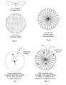
- Figure 5 shows the elevation pattern (side view) and azimuth pattern (top view) of energy radiated from a typical omni-directional antenna.
- the antenna power gain is the ratio of power input into the antenna to the power out (usually measured in dBi; the logarithmic gain relative to an isotropic (perfect spherical radiation pattern) antenna which has a linear gain of one).
- the directive gain is a measure of the concentration of the radiated power in a particular direction and is usually expressed as a ratio of the intensity in a directed orientation (over restricted azimuths) to the average intensity.
- Adaptive array antenna systems that adapt their coverage patterns
- switched beam antenna systems using beam combining strategies of multiple antennas to form beams with special selectivity
- Coverage can be directed in azimuth and elevation. Both systems increase gain by forming specific beam patterns according to the location of the user, or other stations, in communication with the smart antenna station (directing the main lobe at the users/stations). although adaptive array antenna systems attempt to track and minimize interference.
- Figure 6 shows a top view of a typical switched beam coverage pattern, substantially covering the area depicted in Figure 5 .
- an adaptive array system can direct the main lobe at the user and direct a null at the source of interference (as shown in Figure 7 )
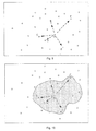
- the main aim of ODMA is the collection of a predetermined number of neighbors which will be changing as the conditions change and/or as stations move or switch off etc. Consequently, as shown in Figure 8 , the present invention provides for the coverage pattern to extend as required to maintain the requisite number of stations (solid black) as neighbors through probing from the stations available (white).
- a null has been directed at the source of interference to minimize the effect of the interference, while maintaining coverage elsewhere. However, it can be seen that the formation of the null has excluded one of the stations (white) from being considered as a potential neighbor.
- the interference could actually be emanating from one of the neighbors of the station as that station attempts to transmit and receive messages with its own neighbor stations.
- the station receiving the interference can assist the other transmitting station by directing a null at the neighbor transmitting and receiving data, before the station itself transmits its own messages.
- the original neighbor will be able to send and receive messages at lower power levels without experiencing interference from the station itself now transmitting and receiving data; and the station now communicating will not be exposed to the interference from the original neighbor, and consequently its own power levels of emitted radiation to its modified group of neighbors can be minimized.
- steering the null at the neighbor benefits both stations and increases the probability of the transmission or receipt being successful.
- nulls could be steered towards each other by both stations to effect a more complete isolation.
- While the transmission of the slow and fast probes will typically require the sort of pattern shown in Figure 8 , it may be possible to generate more gain by directing a distinct beam on a particular station if needed once a station has been identified for communication. Also, it may be possible to send RTS or CTS messages to certain stations using distinct beams to the stations while reducing the beams in the other sectors to ensure the transmission levels are adequate and avoiding the interference with the nulls formed.
- the background noise level of a station is communicated to other stations so that the other stations can determine the level of power required to communicate with the station. As such, it is possible for a station to map the stations to a particular beam or beams for ongoing communication and to switch the beams on and off for the purpose of receiving or transmitting the RTS/CTS messages or the data based on criteria to avoid interference.
- the interference may emanate from multiple sources, particularly in omni-directional coverage areas. By nullifying the noise neighbors will be excluded; and too many nulls will limit the available diversity. Switched beam antennas and phased array antennas can steer nulls dynamically, which will also create peaks and troughs in the area of coverage that will affect the connectivity conditions experienced by the neighbors as signals transmitted strengthen and weaken.
- This dynamic null creation at dominant interference sources, and the dynamic switching of antennas, will consequently automatically create diversity between the stations that are neighbors with each other by influencing the connectivity conditions and thereby varying the opportunities that will be available.
- Some stations will experience worse connectivity by virtue of the nulls and/or increased gain directed in certain directions, while others will identify peaks of opportunity. Therefore instead of simply monitoring the connectivity conditions in the environment and reacting, the antenna system will be able to reduce the impact of certain interference sources momentarily, enabling it to communicate at more efficient power levels with the stations that are relevant and to move the null(s) as needed in order to communicate with the various stations.
- a station can locate and utilize the clear segments, or holes/gaps in the interference, that are available in a noisy environment and get the data through where other transport mechanisms following a defined path would simply fail.
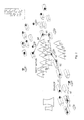
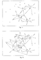
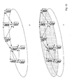
- Figure 9 shows a number of stations A to F in a WLAN region. Using basic ODMA over wireless techniques, station A collects and maintains 5 close neighbors (B-F).
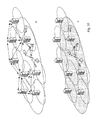
- Figure 10 shows a simplified top view of the radiation coverage at a particular moment in time during the probing. In Figure 11 , it is shown that A's neighbors have each in turn collected 5 neighbors (some of which are shared) and Figure 12 shows the neighbors collected by the neighbors of stations B and C (obviously the neighbors of D, E and F will also be collecting neighbors, but for the purpose of clarity this is not shown).
- Figure 13 shows that were a message to be communicated between station A and a station X, there are numerous routes that could be taken (and combinations thereof); four initial paths leaving A are shown, with each node along the way having various choices available to be made opportunistically.
- the antenna on station A responds by directing a null in the direction of the inference source (as shown in the coverage pattern).
- station C is no longer visible to station A; and instead the slow probes identify G as a new close neighbor.
- station A would not have been able to communicate with station C or X as such systems focus a one-to-one exchange. It is the ability to find a new path around the interference opportunistically which enables the interference problem to be overcome.
- Another mechanism for avoiding the interference in an ODMA network environment is to utilize the auxiliary or macro site introduced in Figure 3 . If one or more of the antennas described above were hard-wired together, to provide very fast and reliable links, it would be possible to hop out of a wireless area with high interference, then hop through the wired connection onto an auxiliary link or network, and then hop back into the WLAN (bypassing the interference). Indeed, in cluttered environments at ground level, stations with the antennas described above could be located at the more cluttered ground level; such that certain interference could be nullified in order to receive a clear signal from the communicating station.
- next hop could then be via ODMA over Ethernet and via a wired connection up the building to the rooftop high site where the next hop could be via an auxiliary network, such as ODMA over Internet; or the next hop could be wireless again on the same channel (for reuse of the channel resources) or on a different channel (for example, 802.11 a instead of 802.11 g used on the ground). In either event, the interference would be avoided.
- auxiliary network such as ODMA over Internet
- microwave links between the macro sites form a private connectivity cloud.
- the microwave links could be a private "Internet” (IP network) and/or could be connected to the Internet at large (confer Internet browsing).
- IP network private Internet network
- private Internet addresses will be allocated to the stations which will all be required to report in to the Location Registration and Matching Server and the Authentication and Certification Servers.
- ODMA over Internet methodology is described in International Patent application PCT/IB2006/001274 and is not only cheaper to deploy (being comprised of standard off-the-shelf components) than a wired network (such as Ethernet), but it is also more efficient in terms of capacity and throughput; as it is point-to-point and utilizes less resource overhead due to the "neighbors on demand” functionality.
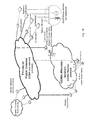
- Figure 16 illustrates in a simplified schematic form the macro site wide area network, where access seeds are focused down in different directions to ground level and some may be positioned at ground level. Indeed, booster seeds may be used to relay from the macro site, off the roofs of houses nearer ground level, and then to relay into buildings (although this becomes less relevant as the subscriber density reaches the critical mass needed full indoor penetration).
- the macro sites may be connected to one or more other macro sites by wire or virtual wire connection.
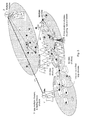
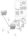
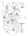
- Figure 17 shows a portion of a network incorporating the abovementioned functionality; having a lower level (cluttered) ODMA wireless domain (A-Stations) in communication with access seeds (B-stations) that are typically located at ground level (although not necessarily).
- the access seeds (802.11g) are wired through concentrator (C-stations) to the high site radios providing connectivity to the macro sites (through 802.11 a).
- the macro sites are in turn in communication with other macro sites (typically by dedicated point-to-point channels).
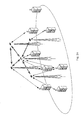
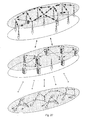
- Figure 18 shows the topology of such a network, comprising two tiers (levels) of connectivity, with the upper tier (forming the optimized central auxiliary network) raised out of the clutter using optimized connections.
- connections are "virtual" wire point-to-point directed wireless connections, but these could be any point-to-point connection such as optical fiber, microwave etc.
- the wireless and auxiliary networks are connected together via concentrators, which have the ability to communicate in the different ODMA protocols (Wireless, Ethernet and Internet; which may each utilize specialized opportunity driven data transport mechanisms).
- ODMA protocols Wireless, Ethernet and Internet; which may each utilize specialized opportunity driven data transport mechanisms.
- Stations in the wireless clutter need only route through 1 to 4 hops (or so) to reach a site having connectivity to the upper tier, or the routing can still be effected wirelessly over more hops if needed.
- the stations are not dedicated to a single concentrator for access to the IP tier, being able to hop wirelessly to others that may be accessible, routing can take place over the best paths available at any time.
- the "wired" auxiliary part of the network is not necessarily the Internet backhaul as such (although it could be).
- Management servers required to operate the network, and the gateways to applications, connect through the auxiliary network and may be located remotely relative to the wireless parts of the network, which in turn may be connected all around the world.
- the gateways and network servers may be placed anywhere having connectivity to the auxiliary network layer, redundancy is built in and subscriber devices will have the ability to choose available gateways opportunistically.
- Figure 19 shows that the point-to-point nature of the macro links of Figure 16 effectively forms an amorphous network cloud of connectivity (just as the Internet at large does in more comprehensive scale).
- the cloud can be extended by adding more links between the macro high sites and the boosters.
- Figure 20 shows the wireless ODMA activity in selected areas of macro coverage. Not only does the macro system create additional diversity by providing access to an auxiliary network, but it will be seen that ODMA over wire operates on a micro and macro level as well. By nullifying interference at the high sites, it may be possible to take very long ODMA over wire hops between the macro sites (in addition to or in combination with the wire or virtual wire connections) and to subscribers and seeds below, thereby further increasing the diversity.
- Beam forming can be achieved by three broadly defined mechanisms.
- a single beam can swivel around an area through defined scan positions, dwelling at each position for a predetermined period. This is termed “scanning” and is not particularly efficient as while the beam is locked into a position it may miss opportunities in other positions. In an ODMA context this will create opportunities, but the collected neighbors will not be stable (depending on the narrowness of the beam).
- a multi-beam approach increases the complexity but provides enhanced sensitivity in respect of the receiving capability and narrow beams can be used for transmission which is very fast and efficient.
- An omni-beam or broad beam approach involves monitoring broadly and converging on a point when appropriate. This mechanism would utilize the RTS/CTS mechanism, but suffers from the same issue as the scanning approach in that other opportunities might be missed while focused.
- the scanning and omni-beam limitations can be mitigated if two or more units are wired together (as a single combination unit or as independent devices), in which case one station could monitor broadly for neighbors, while the other converges as needed.
- two or more receivers are required for this approach, but if there are two or more transceivers the combination can probe and transmit simultaneously.
- the station monitoring broadly could be placed at an elevated location (such as the roof) while the other scans and communicates lower down (in the cluttered street level, for example).
- Such systems can be differentiated from conventional sectorization techniques as the stations located are monitored broadly, but the stations and the beam patterns utilized are chosen and adapted opportunistically at the moment to transmission.
- the amount of data flowing across the network will effectively load the network dynamically; and as the station buffer size may be utilized in the calculation of the cost function, the variations in load will effectively produce opportunities as transmissions of data flow across the network. As more data flows, the network itself will begin contributing to the interference experienced in other parts of the network; and this will also need to be avoided through the switching of channels and antennas by the selection of radios described below.
- radios may be provided on any high site, which are typically connected together with ODMA over Ethernet.
- the radios may each be operational on a different channel, or scanning for channels free of interference; consequently, these radios are in effect creating a multi-beam and multi-channel environment and, as such, will experience different levels of interference on the different beams and channels.
- the interference conditions may be accounted for in the cost function applied in the fast probe and can be opportunistically detected, as this information is included in the probes and is used by other stations in evaluating the cost.
- the multi-beam and multi-channel features provided by the cluster of radios will effectively produce an adaptive opportunistic environment; because the ODMA over Ethernet and the fast probing and slow probing will redirect the traffic load onto the different radios in the cluster as their cost functions change, as detected by slow probe and fast probe mechanisms.
- the data will still be directed opportunistically to more optimal radios, and to the associated channels and antennas, even where the more powerful and robust data transport protocols are not used.
- opportunities will predominantly be detected through the fast probe and slow probe processes and the data will still follow opportunistic routes from each high site (cluster) to other high sites (clusters) as the variations in interference and traffic load cause changes to the cost functions.
- the load of data, and buffer size of accumulated data can also be used in the selection of the radio in the cluster chosen for use for the next hop, as this information can be included in the cost function and then detected as part of the fast probing. This will compensate for the simplified data transport.
- the data will potentially need to follow different opportunely chosen paths within clusters, and from cluster to cluster, and if necessary the path may include more hops to reach the destination cluster.
- the cluster to cluster multi-hop path can be made very reliable and more immune to interference, while still maintaining high throughput due to the faster data transport.
- the opportunities are being detected within the cluster, as opposed to at each radio in the cluster.
- Each radio in the cluster will still be able to choose which neighbor to use opportunistically, but this will be mainly at the fast probe and slow probe level.
- Figure 21 shows schematically a simplified urban environment with buildings and pre-existing cell phone towers in accordance with another embodiment of the invention.
- multiple tier architectural topologies in such an environment.
- sites located well above the clutter masts, towers or tall buildings
- antennas pointing at each other as directional antennas or as sectored and/or narrow vertical beam systems
- These antennas may only have sight of one or two other sites, but by providing different directions and channels each site may be able to form a mesh network with multiple similar stations.
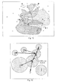
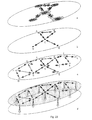
- FIG 22 (a) a dedicated point-to-point directed antenna link is shown between two stations.
- a narrow vertical beam (360 degree) multi-beam antenna has been added.
- the antenna mav be a multi-beam antenna, in which event if monitoring takes place on multiple beams many receivers would be needed to be active at the same time, or the antenna could be a switched beam antenna (with one radio) as shown in Figure 6 . In any event, at least one new separate radio (and therefore a second channel) is available.
- a third channel has been included.
- Figure 22 (d) Three stations in communication with each other are depicted in Figure 22 (d) , and the available channels between the stations are represented in Figure 22 (e) .
- the additional antennas in Figures 22 (c) and (d) would more appropriately be multi-beam, multiple receiver/transmitters as there is more connectivity. By forming a single, narrow beam on the various channels, a null is effectively created elsewhere which prevents interference.
- FIG 23 (a) Similar stations are represented in Figure 23 (a) , showing the channels and nature of the narrow beam and dedicated high gain links; and this connectivity is simplified in Figure 23 (b) .
- Figures 23 (c) and (d) where other similar stations with connectivity on the network are depicted (but not contemplated in the following description) the stations are located at the top of towers or other very high sites.
- This upper level in the illustrated embodiment is typically operating in 802.11 a, where multiple orthogonal channels are available and the interference between them is reduced through the separation.
- These stations will probe and discover other stations on the upper level and mesh together, enabling very high throughput (10s of Mbps) over great distances (5 -10km due to the line of sight, high gain antennas).
- tower 3 could instead send data via tower 4 for example (which by virtue of the narrow beam can avoid sight of towers 1 and 5 on the channel).
- the data can then route to tower 5 via tower 6, or tower 4 might be able to establish tower 5 as a neighbor. Avoiding any interference in this manner, by choosing discrete beams in directions that do not point at other towers, facilitates optimal traffic reuse.
- Beneath the upper level is an intermediate level, as depicted in Figure 24 , where stations located on high sites are in dedicated connectivity with one or more of the stations on the upper level. In the present embodiment, this is through a directed high gain antenna on the 802.11 a band with line of sight.
- the stations may also have relatively narrow vertical beam antennas, or directed or sectored antennas, operating horizontally to enable the intermediate level stations to mesh with each other (probing and discovering neighbors).
- the stations on the intermediate level also have antennas (operating on 802.11 g) directed downward towards the lower, cluttered level (typically street level) as shown in Figure 26 (a) and (b) .
- the a-band and g-band stations are typically hard-wired to each other using ODMA over Ethernet, enabling the g-band stations to be located on the roofs, or at street level as desired.
- Links may be available on a cluster of different channels and are highly optimized, with dedicated directed antennas or narrow vertical beam antennas with excellent line of sight.
- the stations scan all the channels available and determine one or more channels that are appropriate.
- One channel is likely to be maintained as a fixed channel for the transmission, but more may be used in parallel, for redundancy or for load balancing as appropriate.
- Multiple transceivers may be provided in the cluster, linked by ODMA over Ethernet, and still produce fixed beams as depicted in Figure 6 by joining up the clusters; where traffic is automatically received on one beam, sent over ODMA over Ethernet, and then transmitted out of other beams or antennas.
- These links are obviously less rugged than normal ODMA over wireless, but due to the optimization the channels are highly efficient. Peaks of opportunity are available due to the interference, noise and fluctuations in path loss, leading to peaks and troughs as antennas are switched and different channels are used. Diversity is available by virtue of the channels available, and the availability of other stations in the mesh to relay. Spokes of connectivity are directed down from the upper level to the intermediate level, using dedicated, directed antennas with high gain. A number of antennas could point down to the next level, or substantially horizontally on the same level, to provide diversity in the same way.
- the same high speed data transport protocol is used as in the upper level.
- the stations at this level are typically on mid-level buildings, and have a-band connectivity to the upper level, and g-band connectivity (wired to the a-band radio) to reach the lower level.
- the radios may also mesh with other stations on the intermediate level, although a clear view to other sites may not always be available.
- the g-band radios (B-stations) are typically attached via concentrators (C-stations) to the a-band radios as previously described.
- a message from the lower wireless level may be routed from the intermediate level directly to an upper level station, or through several intermediate level stations to an upper level station, or may remain at the intermediate level before returning to a lower level destination.
- the diversity is consequently available on both the upper and intermediate levels by virtue of the multiple high sites and tower sites available, without necessarily needing to change channels.
- This enables use of the high speed data transport protocol, which may simply consists of DATA/ACK exchanges on the dedicated one or more channels identified (which are optimized).
- fast probes may be passed through the upper layers
- the high speed data transport on the intermediate and upper levels may reduce overhead by limiting the utilization of the fast probes to the lower level (to locate the concentrators available).
- the neighbors on demand functionality over the ODMA over Internet also minimizes traffic load over these channels.
- An ODMA multi-station network comprises a number of independent stations, which may be fixed or mobile, each of which can transmit and receive data in order to transmit messages from originating stations to destination stations opportunistically via intermediate stations.
- each station In order for an originating station to be in a position to send a new message to a destination station via a selected one of several possible intermediate stations, each station must at any time normally be in contact with several other stations. This applies also to the case where stations are required to relay a message from an originating station to a destination station.
- each station selects one of a number of possible probing channels to transmit probe signals to other stations.
- the probe signals contain data identifying the station in question and include details of its connectivity to other stations.
- Other stations receiving the probe signals respond directly to the probing station or indirectly, via intermediate stations, thereby indicating both to the probing station and other stations their availability as destination or intermediate stations.
- the probing station evaluates the direct or indirect responses to identify other stations with which it can communicate optimally.
- ODMA Opportunity Driven Multiple Access
- the ODMA-over-wireless methodology is used in a communication network which has a number of wireless stations which are able to transmit data to and receive data from one another.
- the methodology comprises defining a first probing channel for the transmission of first, broadcast probe signals to other stations. These probe signals can also be referred to as neighbor gathering probe signals. Other stations which receive the first probe signals (also referred to as "slow probes") from a probing station indicate to the probing station their availability as destination or intermediate stations (i.e. as neighbors of the probing station). A neighbor table comprising details of, and connectivity data relating to, these other available stations is maintained at each of the stations.
- ODMA network when there are a number of stations in close proximity they will end up probing at higher data rates and lower transmit powers. Listening stations will occasionally respond to stations that are probing at the lower data rates, or that do not have enough neighbors, to help any lonely (distant) stations (also referred to as "lonely neighbors”) that cannot use the higher data rates or do not have sufficient neighbors. Stations will only use the lower data rates when they are lonely and cannot find sufficient neighbors at the higher data rates and at maximum power.
- ODMA networks typically utilize two kinds of probing processes, “slow probing” and “fast probing".
- the slow probing process is used by each network station to gather neighbors, while the fast probing process is used to construct gradients between originating and destination stations.
- Each station will transmit slow "neighbor gathering" probe signals at regular intervals (determined by a Slow Probe Timer) trying to find other stations.
- Stations indicate in their slow probes that they are able to detect other stations probing and in that way stations will vary their probe power until a certain predetermined number of stations indicate they are able to detect the probes. If a station never acquires the required number of neighbors it will remain at the lowest data rate and maximum transmit power.
- Each station will randomly vary the Slow Probe Timer slightly between slow probe signal transmissions to avoid collision with other stations. Should any station start receiving another station's transmission, it will reload the Slow Probe Timer with a new interval.
- the stations are constantly moving, and as such the number of neighbors will constantly be changing. If the number of neighbors exceeds the required number, a station will start to increase its data rate on the probing channel. It will continue to increase its data rate until it no longer exceeds the required number of neighbors. If it reaches the maximum data rate it will start to drop its slow probe transmit power by small increments until it either reaches the minimum transmit power, or no longer exceeds the required number of neighbors.
- the station that is requesting the change will randomly select one of the available Data Channels. When the other station receives the request it will immediately change to that Data Channel, where the two stations will continue to communicate until neither of them have any data to send, or if the maximum time for remaining on the Data Channel expires (set by a Data Timer).
- Alternative data transport protocols could also be used.
- the slow probing process consists of three basic functions:
- the process of neighbor collection consists of a station probing at increased levels of power until neighboring stations indicate in their own probes that they are detecting the probes of the first station.
- the power of the probe is increased until a predetermined number of neighbors indicate that they are detecting the probes.
- All probing stations increase and decrease their probe power until all stations have collected a predetermined number of neighbors. This process consists of increasing and decreasing the power level of probes and indicating in probes which other stations' probes are heard. In this way all stations can learn what power level they require to reach various neighbors.
- a station If a station has a message (or other data) to transmit to a station that is not one of its neighbors, for example, a distant station across the network, it begins to transmit fast probe signals (or gradient gathering probe signals) to develop information on how to reach that station.
- the information is called a gradient and is an indication of the cumulative cost to reach a destination station.
- a station starts to fast probe it indicates that it is looking for a destination and neighbors hearing the fast probe will themselves fast probe until the destination station hears the fast probes of its neighbors.
- the gradient is then built through adding cumulative cost until the gradient reaches the source, and the source can commence to send messages to neighbors using the information developed in the gradients to destination, which in turn can send them to their neighbors until the destination is reached.
- Each station keeps a record of the (cumulative cost) gradients to each destination of each of its neighbors, and its own gradient to the destination.
- each station only passes messages to stations with a lower cumulative cost to destination.
- a station can pass a message to any of its neighbors with a lower gradient to destination.
- Neighbor gathering via slow probing and gradient generation via fast probing allow a station to develop a number of choices of stations with lower cost to any destination that can send messages to such destinations.
- the neighbors are maintained all the time via slow probing and gradients are only developed on a needs basis when messages/data needs to be sent to stations that are not neighbors.
- Each wireless station uses the slow probing process to identify and obtain information from the station's neighbors.
- a station is considered a "neighbor" in this sense if it has been heard to transmit a neighbor gathering probe message, and details of the neighboring stations identified will be maintained in each station's neighbor table.
- an identified neighbor has itself transmitted a neighbor gathering probe message that is received by a particular station, and the probe contains information of the particular station's own identifier, then the neighbor is flagged as a "detecting neighbor" in the neighbor table.
- each station will adapt its neighbor gathering techniques (generally by increasing data transmission rates and by powering down the strength of the probe signals sent out) to maintain approximately 10 detecting neighbors.
- a predetermined number of the neighbors with the lowest path loss are flagged as "close neighbors" (for example, five stations).
- the information obtained from close neighbors may be treated differently or preferentially and the techniques used to transmit the information may also be adapted depending on the neighbors.
- a station If a station is unable to acquire the minimum number of close neighbors when it is transmitting on full probe power, it is referred to as a "lonely neighbor". Other stations that have acquired the required number of close neighbors that can detect the lonely neighbor transmissions will let the lonely neighbor know that they are detected, and may provide additional information to the lonely neighbor.
- each station When not probing or sending other messages, each station is listening for the probes of the other stations. When heard, the receiving station can use the transmit power information provided in the probe to establish the path loss to the station. As each station is constantly identifying the close neighbors with the lowest path loss, these neighbors are likely to be either in direct line of sight, or have the best signal with least interference.
- the global ODMA network architecture enables the implementation of the ODMA network over a very wide area, such as in a regional, national or global networks, by integrating wireless ODMA networks with one or more auxiliary packet switched networks using adapted forms of ODMA techniques.
- the auxiliary network could comprise conventional wired networks, such as Ethernet networks and the Internet, as well as "virtual" wired networks, such as the network created using satellite nodes, or any combination of these networks.
- a component of the communication network of the invention is true peer-to-peer connectivity between a large number of moving ODMA subscriber stations, whether they are proximally close together or in different countries.
- Such peer-to-peer connectivity is offered over an auxiliary network which can use a different transmission medium from the mobile ODMA stations.
- auxiliary network which can use a different transmission medium from the mobile ODMA stations.
- Several actual "wired” and virtual “wired” packet switched media are available for use in such a "global network", but the most relevant of these media is the internet or a private "internet”.
- the mobiie subscriber stations should have many potential access points to the auxiliary network.
- data transmissions should be routed through the most suitable wireless or wired media available at the moment the transmission is being sent onward, using ODMA protocols.
- the location of the access points with optimal connectivity to the other wireless stations should be known with some certainty at any given time and this information should be refreshed on an ongoing basis due to the movement of the wireless stations.
- the manner in which stations are located should also be achieved without overburdening the auxiliary network medium with unnecessary probing transmissions.
- Figure 32 shows the topology of the global ODMA wide area network in a simplified schematic form.
- Message data may be transmitted from one mobile, wireless subscriber station (the originating station) to another (the destination station) within the immediate wireless area (ODMA over Wireless), or over a multi-medium ODMA network.
- the message data is transmitted first over a wireless medium by the originating station, then over a wired medium (over one or more Ethernet networks and the public or private Internet network) before finally being transmitted again through a wireless medium to the destination station.
- Various devices in the wide area communication network may be required to handle more than one disparate communications medium in order to communicate from originating station to destination station using the ODMA protocols. Since the characteristics of the various media vary greatly, different protocols and algorithms are adopted to handle the processing of the data transmission through each medium.
- each medium e.g. wireless, Ethernet and Internet, etc.
- protocols ODMA over Wireless, ODMA over Ethernet, ODMA over Internet, etc.
- a device has its own neighbor table and associated parameters which are of relevance to the medium. Neighbor gathering and the gathering of information relating to the quality of connectivity between stations is undertaken separately in each medium as appropriate, depending on the parameters that are relevant for that medium.
- the gradient table constructed from originating station to destination station is common to all the various media, regardless of which media are utilized, and the gradients identified would be based on all the relevant neighbor information through each medium. Consequently, it should be evident that the gradient table is independent of any medium through which the data is actually subsequently transmitted.
- Probing is undertaken via Ethernet broadcast packets. Data transmission is effected via directed Ethernet packets. Since slow probing is done relatively rarely, and neighbor costs are essentially all the same, the neighbor table could have a large number of neighbors relative to other media.
- the access seed station can develop sets of neighbors where it is the point of connectivity between different Ethernet networks (each on the sections of the Ethernet joined by the ODMA unit). If one local area network is particularly busy and over utilized for either global or local traffic, the ODMA methodology is applied to the traffic in both neighborhoods. Each Ethernet group of stations cannot see the other group's stations as neighbors, but the access seed station acts as an intermediary which matches stations in each group when appropriate thereby serving as a local area multi-hop relay and facilitating one or more hops over the neighborhoods in the Ethernet medium. It will be appreciated that more than one access seed station could be joined to two (or more) local area networks of this nature.
- the general ODMA environment envisages that every wireless station (wireless subscriber stations and seed stations) in the network repeatedly sends updated authentication messages on a periodic basis to the Authentication and Certification Servers. This is typically achieved through the Station Location Recording and Matching Server functionality.
- a wireless station When a wireless station sends a packet to the Authentication and Certification Server (up a gradient to the Authentication and Certification Server), it includes the information for the predetermined number of best concentrator stations that it has determined provide the best potential connectivity in the area of the wireless station. Each time an authentication packet is sent to the Authentication and Certification Server it will follow a gradient via a concentrator station and this information will also be added to the authentication packet.
- the Station Location Recording and Matching Server will consequently always have a relatively current record of the wireless stations that are in the area of certain concentrator stations. In addition, the wireless stations will know how to send an authentication to the Authentication and Certification Server at all times.
- any wireless station (the originating station) wishes to send information to another wireless station (the destination station) that it cannot contact by ODMA over wireless, it sends a packet to the Station Location Recording and Matching Server (typically via the best-placed concentrator stations in its area, although the message could in theory be transmitted over the wireless medium if the Server has this functionality). Packets may be sent to both the Station Location Recording and Matching Server and concentrator stations nearbv to establish the best route available from the originating station to the destination station over the auxiliary network, as the destination station might already be known to a concentrator station.
- the Station Location Recording and Matching Server typically via the best-placed concentrator stations in its area, although the message could in theory be transmitted over the wireless medium if the Server has this functionality.
- Packets may be sent to both the Station Location Recording and Matching Server and concentrator stations nearbv to establish the best route available from the originating station to the destination station over the auxiliary network, as the destination station might already be known to a concentrator station.
- stations acting as nodes on the Internee do not need to access a Station Location Recording and Matching Server as such.
- the station When switched on, with access to the Internet (or other packet switched network), the station will automatically start probing for neighbors. There could be one or more initial addresses provided in the station's hardware to get the process going, and the addressee station(s) probed will provide information in respect of their own "well connected" neighbors and thereby advise of other stations that could be probed. All stations will ultimately locate each other in this manner as more addresses are made available to probe. As these neighbors are generally well connected, it is likely that they will have good connectivity with other well connected neighbors which ensure optimal transactions generally.
- a station on the Internet can locate wireless stations through this probing mechanism as well.
- the neighbor tables of the stations are updated on an ongoing basis, so any station should be able to keep track of well connected neighbors of its own and those of the destination station (whether on the auxiliary network or the wireless network). Once found, the key stations to probe as "neighbors on demand" can be updated continuously for as long as needed.
- the Station Location Recording and Matching Server will then determine the last known location of the destination station and establish from its tables which concentrator stations appear best suited for connectivity between the originating and destination stations.
- the Station Location Recording and Matching Server will tell the concentrator stations on the "originating side" of the Internet which other concentrator stations to probe via UDP on the "destination side.”
- the best concentrator stations (as may be determined on an ongoing basis thereafter) in the region of the originating and destination stations will then be probing each other as long as the stations on both sides of the Internet "hop" require a gradient between them.
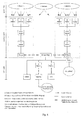
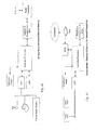
- a Multi-Tier architecture is depicted in Figure 33 and consists of the following primary devices.
- Element Definition Access Site Acting as the access to an IP backhaul, it facilitates management services for subscribers and provides high-bandwidth Internet access.
- CPE Customer-premises equipment, on-site wireless devices connecting fixed or portable computers or other devices (e.g. PDAs) to ODMA wireless networks.
- Outdoor Seed A device combining the functions of B, C (and usually ODMA gateway) stations. Used to associate CPEs in a Cell.
- Backbone Seed A device operating in WS mode when wired to an Outdoor Seed in a Cell; and used independently in AP mode to connect to Clouds. Cell Group of CPEs associated together by an Outdoor Seed and Backbone Seed. Cloud Group of Cells connected by Backbone Seeds.
- the Multi-Tier Access Site typically consists of the following devices. Level Components Access site ODMA Gateway and Concentrator combinations Locator (LRMS) Authenticator (AAA) with Concentrator Network Management Server (CNMS) IP Gateway, for Internet connectivity at large
- An ODMA Cell is shown in more detail in Figure 34 and consists of one Outdoor Seed and Backbone Seed wired pairing and a number of CPEs in connectivity.
- the Outdoor Seed uses an omni-antenna or sector antenna to enable appropriate wide coverage of the local area.
- the Backbone Seed uses a directed antenna to connect in wireless station ("WS mode") to another Backbone Seed, typically located near the center of the Cloud.
- WS mode wireless station
- Each 802.11g CPE located in the Cell and linked to the Outdoor Seed presently has a throughput of 300Kbps or more over 4 hops and 3Mbps over 1 hop.
- the typical coverage of a Cell is a radius of 300m over 1 hop.
- ODMA CPEs located in an ODMA Cell will connect through the 802.11a Outdoor Seed to the ODMA network.
- Each CPE can link to the Outdoor Seed by one or more hops. The distance between each peer is typically 50-300m. All peers in the Cell can connect outside the ODMA Cloud or to the Internet through a Backbone Seed wired with an Outdoor Seed, located in each Cell.
- Backbone Seeds are configured to connect back to an "AP mode" Backbone Seed located on other towers or high sites.
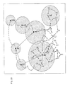
- An ODMA Cloud is shown in Figure 34 , composed of Backbone Seeds located near the center of the Cloud, and a number of ODMA Cells linked to each other by these Backbone Seeds. These links will have a bandwidth of 3Mbps or more.
- Each Backbone Seed typically uses a 120° patch antenna to provide part of a wide area of coverage, and is mounted on a highly elevated site.
- Backbone Seeds extend ODMA coverage by connecting Cells in Clouds, providing multiple redundancy and increased throughput.
- another Backbone Seed uses a dedicated high-gain antenna to link back to the Access Site through another Backbone Seed located on another tower, directing CPE traffic to and from the ODMA infrastructure over that 802.11 a band.
- the trunk links have clear line of sight to neighboring Backbone Seeds, operating high above the clutter, and have a bandwidth of approximately 10-20Mbps depending on the conditions.
- Cloud coverage is typically a radius from 1-10km (Line of Sight - LoS), being dependent on antenna and conditions.
- Outdoor Seeds provide last-mile connectivity over the ODMA network; typically being placed on the roof of a house. Throughput is approximately 3Mbps, using an omni-antenna over the 802.11g band.
- ODMA Clouds provide redundancy in the event of connection failure between the Backbone Seeds. Peers in the affected Cell can hop to another Cell and access the Backbone Seed belonging to that other Cell. For example, if the connection to the G7 Backbone Seed of Figure 34 was unavailable, peers within the Cell could connect to the G6 Backbone Seed instead, and use it to reach the trunk link.
- Typical antenna Requirements are as follows.
Landscapes
- Engineering & Computer Science (AREA)
- Computer Networks & Wireless Communication (AREA)
- Signal Processing (AREA)
- Mobile Radio Communication Systems (AREA)
- Radio Transmission System (AREA)
Applications Claiming Priority (3)
| Application Number | Priority Date | Filing Date | Title |
|---|---|---|---|
| US87490206P | 2006-12-14 | 2006-12-14 | |
| EP07849495A EP2103163B1 (de) | 2006-12-14 | 2007-12-14 | Adaptives antennensystem für diversität und störungsvermeidung in einem netzwerk mit mehreren stationen |
| PCT/IB2007/055117 WO2008072210A2 (en) | 2006-12-14 | 2007-12-14 | Adaptive antenna system for diversity and interference avoidance in a multi-station network |
Related Parent Applications (2)
| Application Number | Title | Priority Date | Filing Date |
|---|---|---|---|
| EP07849495.2 Division | 2007-12-14 | ||
| EP07849495A Division EP2103163B1 (de) | 2006-12-14 | 2007-12-14 | Adaptives antennensystem für diversität und störungsvermeidung in einem netzwerk mit mehreren stationen |
Publications (2)
| Publication Number | Publication Date |
|---|---|
| EP2472801A1 true EP2472801A1 (de) | 2012-07-04 |
| EP2472801B1 EP2472801B1 (de) | 2020-05-06 |
Family
ID=39415010
Family Applications (2)
| Application Number | Title | Priority Date | Filing Date |
|---|---|---|---|
| EP12161497.8A Active EP2472801B1 (de) | 2006-12-14 | 2007-12-14 | Adaptives Antennensystem für die Diversitäts- und Interferenzverhinderung in einem Mehrstationsnetzwerk |
| EP07849495A Active EP2103163B1 (de) | 2006-12-14 | 2007-12-14 | Adaptives antennensystem für diversität und störungsvermeidung in einem netzwerk mit mehreren stationen |
Family Applications After (1)
| Application Number | Title | Priority Date | Filing Date |
|---|---|---|---|
| EP07849495A Active EP2103163B1 (de) | 2006-12-14 | 2007-12-14 | Adaptives antennensystem für diversität und störungsvermeidung in einem netzwerk mit mehreren stationen |
Country Status (5)
| Country | Link |
|---|---|
| US (1) | US8363623B2 (de) |
| EP (2) | EP2472801B1 (de) |
| AT (1) | ATE551855T1 (de) |
| ES (1) | ES2380987T3 (de) |
| WO (1) | WO2008072210A2 (de) |
Families Citing this family (13)
| Publication number | Priority date | Publication date | Assignee | Title |
|---|---|---|---|---|
| KR101395562B1 (ko) * | 2008-02-22 | 2014-05-16 | 삼성전자주식회사 | 다중 홉 중계 방식의 무선통신 시스템에서 전이중 중계 방식 사용시 기지국 및 중계기 간 간섭회피 방법 및 장치 |
| WO2010094336A1 (en) * | 2009-02-20 | 2010-08-26 | Nokia Siemens Networks Oy | Method and network device for managing resource allocation |
| WO2011044947A1 (en) * | 2009-10-16 | 2011-04-21 | Nokia Siemens Networks Oy | Femto access point operable with different spatial characteristic antenna patterns |
| CN102340860B (zh) * | 2010-07-27 | 2014-04-02 | 杭州华三通信技术有限公司 | 一种智能天线系统的功率控制方法和装置 |
| US8619640B2 (en) * | 2010-12-16 | 2013-12-31 | Intel Corporation | Dynamic bandwidth control in interference situations |
| JP6119116B2 (ja) * | 2012-05-30 | 2017-04-26 | 日本電気株式会社 | 無線通信システム、無線通信方法、サーバ、サーバの制御方法および制御プログラム、携帯通信端末、携帯通信端末の制御方法および制御プログラム |
| US9287940B2 (en) | 2012-06-29 | 2016-03-15 | Hewlett Packard Enterprise Development Lp | Wireless network with coordinated sectors to mitigate interference |
| CN103346828B (zh) * | 2013-06-28 | 2016-08-10 | 华为技术有限公司 | 一种级联射频拉远单元转换为直放站的方法及rru设备 |
| US9531482B2 (en) * | 2013-12-04 | 2016-12-27 | Css Antenna, Llc | Canister antenna producing a pseudo-omni radiation pattern for mitigating passive intermodulation (PIM) |
| JP7140977B2 (ja) * | 2019-03-15 | 2022-09-22 | 日本電信電話株式会社 | 干渉評価方法、干渉評価装置、及び干渉評価プログラム |
| CN111277964B (zh) * | 2020-01-22 | 2022-04-01 | 北京市万格数码通讯科技有限公司 | Pdt系统高并发状态的移动终端随机接入方法 |
| US11411613B2 (en) | 2020-12-31 | 2022-08-09 | Rockwell Collins, Inc. | Adaptation of coordinated radio frequency transmissions and receptions |
| CN117784077B (zh) * | 2024-02-27 | 2024-05-24 | 南京奥联智驾科技有限公司 | 一种基于频率积累的弱小目标检测方法、终端及介质 |
Citations (8)
| Publication number | Priority date | Publication date | Assignee | Title |
|---|---|---|---|---|
| WO1996019887A1 (en) | 1994-12-19 | 1996-06-27 | Salbu Research And Development (Proprietary) Limited | Multi-hop packet radio networks |
| WO1998056140A2 (en) | 1997-06-06 | 1998-12-10 | Salbu Research And Development (Proprietary) Limited | Method of operation of a multi-station network |
| GB2349045A (en) * | 1999-04-16 | 2000-10-18 | Fujitsu Ltd | Base station transmission beam pattern forming; interference reduction |
| US20020136179A1 (en) * | 2000-05-26 | 2002-09-26 | Takahisa Aoyama | Array antenna base station device and radio transmission method |
| US20020181444A1 (en) * | 1997-01-17 | 2002-12-05 | Anthony Acampora | Hybrid universal broadband telecommunications using small radio cells interconnected by free-space optical links |
| US20020191573A1 (en) * | 2001-06-14 | 2002-12-19 | Whitehill Eric A. | Embedded routing algorithms under the internet protocol routing layer of a software architecture protocol stack in a mobile Ad-Hoc network |
| US20030120809A1 (en) * | 2001-12-20 | 2003-06-26 | Bellur Barghav R. | Interference mitigation and adaptive routing in wireless ad-hoc packet-switched networks |
| WO2006123218A2 (en) * | 2005-05-16 | 2006-11-23 | Iwics Inc | Multi-medium wide area communication network |
Family Cites Families (9)
| Publication number | Priority date | Publication date | Assignee | Title |
|---|---|---|---|---|
| CA2282750C (en) * | 1997-03-03 | 2008-05-20 | Salbu Research And Development (Proprietary) Limited | Cellular communication system with mobile stations acting as relay stations |
| AU7838198A (en) | 1997-06-13 | 1998-12-30 | Percusurge, Inc. | Syringe and method for inflating low volume catheter balloons |
| NZ502698A (en) * | 1997-08-01 | 2003-03-28 | Salbu Res & Dev Pty Ltd | Power adaption in a multi-station network |
| US6785510B2 (en) * | 2000-03-09 | 2004-08-31 | Salbu Resarch & Development (Proprietary) Limited | Routing in a multi-station network |
| US8213438B2 (en) * | 2003-12-19 | 2012-07-03 | Iwics Inc. | Data transport protocol for a multi-station network |
| US7590068B2 (en) * | 2003-12-19 | 2009-09-15 | Iwics Inc. | Probing method for a multi-station network |
| TW200614759A (en) * | 2004-10-21 | 2006-05-01 | Iwics Inc | Implied acknowledgement data transport protocol for a multi-station network |
| MY163773A (en) * | 2005-09-13 | 2017-10-31 | Taiwan Semiconductor Mfg Co Ltd | Position determination of mobile stations in a wireless network |
| US8976684B2 (en) * | 2005-11-28 | 2015-03-10 | Conversant Intellectual Property Management Inc. | Intelligent video, data streaming and access to distributed resources in a wireless network |
-
2007
- 2007-12-14 AT AT07849495T patent/ATE551855T1/de active
- 2007-12-14 EP EP12161497.8A patent/EP2472801B1/de active Active
- 2007-12-14 ES ES07849495T patent/ES2380987T3/es active Active
- 2007-12-14 US US12/518,905 patent/US8363623B2/en active Active
- 2007-12-14 EP EP07849495A patent/EP2103163B1/de active Active
- 2007-12-14 WO PCT/IB2007/055117 patent/WO2008072210A2/en not_active Ceased
Patent Citations (8)
| Publication number | Priority date | Publication date | Assignee | Title |
|---|---|---|---|---|
| WO1996019887A1 (en) | 1994-12-19 | 1996-06-27 | Salbu Research And Development (Proprietary) Limited | Multi-hop packet radio networks |
| US20020181444A1 (en) * | 1997-01-17 | 2002-12-05 | Anthony Acampora | Hybrid universal broadband telecommunications using small radio cells interconnected by free-space optical links |
| WO1998056140A2 (en) | 1997-06-06 | 1998-12-10 | Salbu Research And Development (Proprietary) Limited | Method of operation of a multi-station network |
| GB2349045A (en) * | 1999-04-16 | 2000-10-18 | Fujitsu Ltd | Base station transmission beam pattern forming; interference reduction |
| US20020136179A1 (en) * | 2000-05-26 | 2002-09-26 | Takahisa Aoyama | Array antenna base station device and radio transmission method |
| US20020191573A1 (en) * | 2001-06-14 | 2002-12-19 | Whitehill Eric A. | Embedded routing algorithms under the internet protocol routing layer of a software architecture protocol stack in a mobile Ad-Hoc network |
| US20030120809A1 (en) * | 2001-12-20 | 2003-06-26 | Bellur Barghav R. | Interference mitigation and adaptive routing in wireless ad-hoc packet-switched networks |
| WO2006123218A2 (en) * | 2005-05-16 | 2006-11-23 | Iwics Inc | Multi-medium wide area communication network |
Also Published As
| Publication number | Publication date |
|---|---|
| ATE551855T1 (de) | 2012-04-15 |
| WO2008072210A3 (en) | 2008-08-14 |
| EP2103163A2 (de) | 2009-09-23 |
| EP2472801B1 (de) | 2020-05-06 |
| WO2008072210A2 (en) | 2008-06-19 |
| US20100034134A1 (en) | 2010-02-11 |
| ES2380987T3 (es) | 2012-05-22 |
| US8363623B2 (en) | 2013-01-29 |
| EP2103163B1 (de) | 2012-03-28 |
Similar Documents
| Publication | Publication Date | Title |
|---|---|---|
| EP2472801B1 (de) | Adaptives Antennensystem für die Diversitäts- und Interferenzverhinderung in einem Mehrstationsnetzwerk | |
| Dai et al. | An overview of using directional antennas in wireless networks | |
| Hossain et al. | Wireless mesh networks: architectures and protocols | |
| US7706320B2 (en) | Mesh based/tower based network | |
| US20240106512A1 (en) | Wireless repeater apparatus and methods of operation | |
| JP4228342B2 (ja) | 無線ネットワークの無線伝送装置、経路制御方法及び経路制御プログラム | |
| JP2003332971A (ja) | 無線ネットワークのための通信方法及び無線ネットワークシステム | |
| Biomo et al. | Directional antennas in FANETs: A performance analysis of routing protocols | |
| JP2007074561A (ja) | 無線ネットワークのルーティング方法及び無線通信システム | |
| GB2455794A (en) | Establishing a multi-hop route in wireless network | |
| CN113573177A (zh) | 一种深空光通信网信道定向接入方法 | |
| JP6957765B2 (ja) | ビームフォーミングを用いる高速マルチホップネットワーク | |
| JP2003115858A (ja) | 無線ネットワークのためのルーティング方法及びルータ装置 | |
| WO2024166765A1 (ja) | 通信中継システム、通信中継方法及びプログラム | |
| Hussain et al. | A WiFi-based reliable network architecture for rural regions | |
| JP2005064672A (ja) | 無線ネットワークのための制御方法及び制御装置 | |
| US9924338B1 (en) | Connecting communication networks via a non-collocated relay | |
| JP2005064671A (ja) | 無線ネットワークのための制御方法及び制御装置 | |
| JP7557817B2 (ja) | ノード | |
| Wu et al. | A survey on directional antenna networking | |
| JP3789813B2 (ja) | 無線ネットワークのルーティング方法及びルータ装置 | |
| JP2004235839A (ja) | 固定無線アクセスシステム | |
| Chen et al. | A range-adaptive directional MAC protocol for wireless ad hoc networks with smart antennas | |
| Adler et al. | A carrier-grade wireless lan network implementation [application notes] | |
| KR20140011236A (ko) | 육상 네트워크 서비스 확장을 위한 무선랜 기반 확장 멀티 홉 릴레이 네트워크 시스템 |
Legal Events
| Date | Code | Title | Description |
|---|---|---|---|
| AC | Divisional application: reference to earlier application |
Ref document number: 2103163 Country of ref document: EP Kind code of ref document: P |
|
| AK | Designated contracting states |
Kind code of ref document: A1 Designated state(s): AT BE BG CH CY CZ DE DK EE ES FI FR GB GR HU IE IS IT LI LT LU LV MC MT NL PL PT RO SE SI SK TR |
|
| PUAI | Public reference made under article 153(3) epc to a published international application that has entered the european phase |
Free format text: ORIGINAL CODE: 0009012 |
|
| 17P | Request for examination filed |
Effective date: 20130102 |
|
| RAP1 | Party data changed (applicant data changed or rights of an application transferred) |
Owner name: CONVERSANT INTELLECTUAL PROPERTY MANAGEMENT INC. |
|
| RAP1 | Party data changed (applicant data changed or rights of an application transferred) |
Owner name: TAIWAN SEMICONDUCTOR MANUFACTURING COMPANY, LTD. |
|
| STAA | Information on the status of an ep patent application or granted ep patent |
Free format text: STATUS: EXAMINATION IS IN PROGRESS |
|
| 17Q | First examination report despatched |
Effective date: 20180228 |
|
| REG | Reference to a national code |
Ref country code: DE Ref legal event code: R079 Ref document number: 602007060234 Country of ref document: DE Free format text: PREVIOUS MAIN CLASS: H04L0012560000 Ipc: H04W0016280000 |
|
| GRAP | Despatch of communication of intention to grant a patent |
Free format text: ORIGINAL CODE: EPIDOSNIGR1 |
|
| STAA | Information on the status of an ep patent application or granted ep patent |
Free format text: STATUS: GRANT OF PATENT IS INTENDED |
|
| RIC1 | Information provided on ipc code assigned before grant |
Ipc: H04W 16/28 20090101AFI20191202BHEP |
|
| INTG | Intention to grant announced |
Effective date: 20191216 |
|
| GRAS | Grant fee paid |
Free format text: ORIGINAL CODE: EPIDOSNIGR3 |
|
| GRAA | (expected) grant |
Free format text: ORIGINAL CODE: 0009210 |
|
| STAA | Information on the status of an ep patent application or granted ep patent |
Free format text: STATUS: THE PATENT HAS BEEN GRANTED |
|
| AC | Divisional application: reference to earlier application |
Ref document number: 2103163 Country of ref document: EP Kind code of ref document: P |
|
| AK | Designated contracting states |
Kind code of ref document: B1 Designated state(s): AT BE BG CH CY CZ DE DK EE ES FI FR GB GR HU IE IS IT LI LT LU LV MC MT NL PL PT RO SE SI SK TR |
|
| RAP1 | Party data changed (applicant data changed or rights of an application transferred) |
Owner name: TAIWAN SEMICONDUCTOR MANUFACTURING COMPANY, LTD. |
|
| REG | Reference to a national code |
Ref country code: GB Ref legal event code: FG4D |
|
| REG | Reference to a national code |
Ref country code: AT Ref legal event code: REF Ref document number: 1268824 Country of ref document: AT Kind code of ref document: T Effective date: 20200515 Ref country code: CH Ref legal event code: EP |
|
| REG | Reference to a national code |
Ref country code: DE Ref legal event code: R096 Ref document number: 602007060234 Country of ref document: DE |
|
| REG | Reference to a national code |
Ref country code: IE Ref legal event code: FG4D |
|
| REG | Reference to a national code |
Ref country code: LT Ref legal event code: MG4D |
|
| REG | Reference to a national code |
Ref country code: NL Ref legal event code: MP Effective date: 20200506 |
|
| PG25 | Lapsed in a contracting state [announced via postgrant information from national office to epo] |
Ref country code: FI Free format text: LAPSE BECAUSE OF FAILURE TO SUBMIT A TRANSLATION OF THE DESCRIPTION OR TO PAY THE FEE WITHIN THE PRESCRIBED TIME-LIMIT Effective date: 20200506 Ref country code: GR Free format text: LAPSE BECAUSE OF FAILURE TO SUBMIT A TRANSLATION OF THE DESCRIPTION OR TO PAY THE FEE WITHIN THE PRESCRIBED TIME-LIMIT Effective date: 20200807 Ref country code: SE Free format text: LAPSE BECAUSE OF FAILURE TO SUBMIT A TRANSLATION OF THE DESCRIPTION OR TO PAY THE FEE WITHIN THE PRESCRIBED TIME-LIMIT Effective date: 20200506 Ref country code: LT Free format text: LAPSE BECAUSE OF FAILURE TO SUBMIT A TRANSLATION OF THE DESCRIPTION OR TO PAY THE FEE WITHIN THE PRESCRIBED TIME-LIMIT Effective date: 20200506 Ref country code: IS Free format text: LAPSE BECAUSE OF FAILURE TO SUBMIT A TRANSLATION OF THE DESCRIPTION OR TO PAY THE FEE WITHIN THE PRESCRIBED TIME-LIMIT Effective date: 20200906 Ref country code: PT Free format text: LAPSE BECAUSE OF FAILURE TO SUBMIT A TRANSLATION OF THE DESCRIPTION OR TO PAY THE FEE WITHIN THE PRESCRIBED TIME-LIMIT Effective date: 20200907 |
|
| PG25 | Lapsed in a contracting state [announced via postgrant information from national office to epo] |
Ref country code: LV Free format text: LAPSE BECAUSE OF FAILURE TO SUBMIT A TRANSLATION OF THE DESCRIPTION OR TO PAY THE FEE WITHIN THE PRESCRIBED TIME-LIMIT Effective date: 20200506 Ref country code: BG Free format text: LAPSE BECAUSE OF FAILURE TO SUBMIT A TRANSLATION OF THE DESCRIPTION OR TO PAY THE FEE WITHIN THE PRESCRIBED TIME-LIMIT Effective date: 20200806 |
|
| REG | Reference to a national code |
Ref country code: AT Ref legal event code: MK05 Ref document number: 1268824 Country of ref document: AT Kind code of ref document: T Effective date: 20200506 |
|
| PG25 | Lapsed in a contracting state [announced via postgrant information from national office to epo] |
Ref country code: NL Free format text: LAPSE BECAUSE OF FAILURE TO SUBMIT A TRANSLATION OF THE DESCRIPTION OR TO PAY THE FEE WITHIN THE PRESCRIBED TIME-LIMIT Effective date: 20200506 |
|
| PG25 | Lapsed in a contracting state [announced via postgrant information from national office to epo] |
Ref country code: IT Free format text: LAPSE BECAUSE OF FAILURE TO SUBMIT A TRANSLATION OF THE DESCRIPTION OR TO PAY THE FEE WITHIN THE PRESCRIBED TIME-LIMIT Effective date: 20200506 Ref country code: RO Free format text: LAPSE BECAUSE OF FAILURE TO SUBMIT A TRANSLATION OF THE DESCRIPTION OR TO PAY THE FEE WITHIN THE PRESCRIBED TIME-LIMIT Effective date: 20200506 Ref country code: CZ Free format text: LAPSE BECAUSE OF FAILURE TO SUBMIT A TRANSLATION OF THE DESCRIPTION OR TO PAY THE FEE WITHIN THE PRESCRIBED TIME-LIMIT Effective date: 20200506 Ref country code: ES Free format text: LAPSE BECAUSE OF FAILURE TO SUBMIT A TRANSLATION OF THE DESCRIPTION OR TO PAY THE FEE WITHIN THE PRESCRIBED TIME-LIMIT Effective date: 20200506 Ref country code: AT Free format text: LAPSE BECAUSE OF FAILURE TO SUBMIT A TRANSLATION OF THE DESCRIPTION OR TO PAY THE FEE WITHIN THE PRESCRIBED TIME-LIMIT Effective date: 20200506 Ref country code: EE Free format text: LAPSE BECAUSE OF FAILURE TO SUBMIT A TRANSLATION OF THE DESCRIPTION OR TO PAY THE FEE WITHIN THE PRESCRIBED TIME-LIMIT Effective date: 20200506 Ref country code: DK Free format text: LAPSE BECAUSE OF FAILURE TO SUBMIT A TRANSLATION OF THE DESCRIPTION OR TO PAY THE FEE WITHIN THE PRESCRIBED TIME-LIMIT Effective date: 20200506 |
|
| REG | Reference to a national code |
Ref country code: DE Ref legal event code: R097 Ref document number: 602007060234 Country of ref document: DE |
|
| PG25 | Lapsed in a contracting state [announced via postgrant information from national office to epo] |
Ref country code: PL Free format text: LAPSE BECAUSE OF FAILURE TO SUBMIT A TRANSLATION OF THE DESCRIPTION OR TO PAY THE FEE WITHIN THE PRESCRIBED TIME-LIMIT Effective date: 20200506 Ref country code: SK Free format text: LAPSE BECAUSE OF FAILURE TO SUBMIT A TRANSLATION OF THE DESCRIPTION OR TO PAY THE FEE WITHIN THE PRESCRIBED TIME-LIMIT Effective date: 20200506 |
|
| PLBE | No opposition filed within time limit |
Free format text: ORIGINAL CODE: 0009261 |
|
| STAA | Information on the status of an ep patent application or granted ep patent |
Free format text: STATUS: NO OPPOSITION FILED WITHIN TIME LIMIT |
|
| 26N | No opposition filed |
Effective date: 20210209 |
|
| PG25 | Lapsed in a contracting state [announced via postgrant information from national office to epo] |
Ref country code: SI Free format text: LAPSE BECAUSE OF FAILURE TO SUBMIT A TRANSLATION OF THE DESCRIPTION OR TO PAY THE FEE WITHIN THE PRESCRIBED TIME-LIMIT Effective date: 20200506 |
|
| REG | Reference to a national code |
Ref country code: CH Ref legal event code: PL |
|
| GBPC | Gb: european patent ceased through non-payment of renewal fee |
Effective date: 20201214 |
|
| PG25 | Lapsed in a contracting state [announced via postgrant information from national office to epo] |
Ref country code: MC Free format text: LAPSE BECAUSE OF FAILURE TO SUBMIT A TRANSLATION OF THE DESCRIPTION OR TO PAY THE FEE WITHIN THE PRESCRIBED TIME-LIMIT Effective date: 20200506 |
|
| REG | Reference to a national code |
Ref country code: BE Ref legal event code: MM Effective date: 20201231 |
|
| PG25 | Lapsed in a contracting state [announced via postgrant information from national office to epo] |
Ref country code: IE Free format text: LAPSE BECAUSE OF NON-PAYMENT OF DUE FEES Effective date: 20201214 Ref country code: FR Free format text: LAPSE BECAUSE OF NON-PAYMENT OF DUE FEES Effective date: 20201231 Ref country code: LU Free format text: LAPSE BECAUSE OF NON-PAYMENT OF DUE FEES Effective date: 20201214 |
|
| PG25 | Lapsed in a contracting state [announced via postgrant information from national office to epo] |
Ref country code: LI Free format text: LAPSE BECAUSE OF NON-PAYMENT OF DUE FEES Effective date: 20201231 Ref country code: GB Free format text: LAPSE BECAUSE OF NON-PAYMENT OF DUE FEES Effective date: 20201214 Ref country code: CH Free format text: LAPSE BECAUSE OF NON-PAYMENT OF DUE FEES Effective date: 20201231 |
|
| PG25 | Lapsed in a contracting state [announced via postgrant information from national office to epo] |
Ref country code: TR Free format text: LAPSE BECAUSE OF FAILURE TO SUBMIT A TRANSLATION OF THE DESCRIPTION OR TO PAY THE FEE WITHIN THE PRESCRIBED TIME-LIMIT Effective date: 20200506 Ref country code: MT Free format text: LAPSE BECAUSE OF FAILURE TO SUBMIT A TRANSLATION OF THE DESCRIPTION OR TO PAY THE FEE WITHIN THE PRESCRIBED TIME-LIMIT Effective date: 20200506 Ref country code: CY Free format text: LAPSE BECAUSE OF FAILURE TO SUBMIT A TRANSLATION OF THE DESCRIPTION OR TO PAY THE FEE WITHIN THE PRESCRIBED TIME-LIMIT Effective date: 20200506 |
|
| PG25 | Lapsed in a contracting state [announced via postgrant information from national office to epo] |
Ref country code: BE Free format text: LAPSE BECAUSE OF NON-PAYMENT OF DUE FEES Effective date: 20201231 |
|
| PG25 | Lapsed in a contracting state [announced via postgrant information from national office to epo] |
Ref country code: IS Free format text: LAPSE BECAUSE OF NON-PAYMENT OF DUE FEES Effective date: 20200906 |
|
| PGFP | Annual fee paid to national office [announced via postgrant information from national office to epo] |
Ref country code: DE Payment date: 20251229 Year of fee payment: 19 |