EP2472812B1 - Architecture VOIP multicellulaire sans fil adaptative - Google Patents
Architecture VOIP multicellulaire sans fil adaptative Download PDFInfo
- Publication number
- EP2472812B1 EP2472812B1 EP10197291.7A EP10197291A EP2472812B1 EP 2472812 B1 EP2472812 B1 EP 2472812B1 EP 10197291 A EP10197291 A EP 10197291A EP 2472812 B1 EP2472812 B1 EP 2472812B1
- Authority
- EP
- European Patent Office
- Prior art keywords
- wireless
- base station
- communication
- network
- communication session
- Prior art date
- Legal status (The legal status is an assumption and is not a legal conclusion. Google has not performed a legal analysis and makes no representation as to the accuracy of the status listed.)
- Active
Links
Images


Classifications
-
- H—ELECTRICITY
- H04—ELECTRIC COMMUNICATION TECHNIQUE
- H04W—WIRELESS COMMUNICATION NETWORKS
- H04W76/00—Connection management
- H04W76/10—Connection setup
-
- H—ELECTRICITY
- H04—ELECTRIC COMMUNICATION TECHNIQUE
- H04W—WIRELESS COMMUNICATION NETWORKS
- H04W36/00—Hand-off or reselection arrangements
- H04W36/0005—Control or signalling for completing the hand-off
-
- H—ELECTRICITY
- H04—ELECTRIC COMMUNICATION TECHNIQUE
- H04L—TRANSMISSION OF DIGITAL INFORMATION, e.g. TELEGRAPHIC COMMUNICATION
- H04L65/00—Network arrangements, protocols or services for supporting real-time applications in data packet communication
- H04L65/10—Architectures or entities
- H04L65/102—Gateways
- H04L65/1033—Signalling gateways
- H04L65/1036—Signalling gateways at the edge
-
- H—ELECTRICITY
- H04—ELECTRIC COMMUNICATION TECHNIQUE
- H04L—TRANSMISSION OF DIGITAL INFORMATION, e.g. TELEGRAPHIC COMMUNICATION
- H04L65/00—Network arrangements, protocols or services for supporting real-time applications in data packet communication
- H04L65/10—Architectures or entities
- H04L65/1053—IP private branch exchange [PBX] functionality entities or arrangements
-
- H—ELECTRICITY
- H04—ELECTRIC COMMUNICATION TECHNIQUE
- H04L—TRANSMISSION OF DIGITAL INFORMATION, e.g. TELEGRAPHIC COMMUNICATION
- H04L65/00—Network arrangements, protocols or services for supporting real-time applications in data packet communication
- H04L65/1066—Session management
- H04L65/1069—Session establishment or de-establishment
-
- H—ELECTRICITY
- H04—ELECTRIC COMMUNICATION TECHNIQUE
- H04W—WIRELESS COMMUNICATION NETWORKS
- H04W36/00—Hand-off or reselection arrangements
- H04W36/0005—Control or signalling for completing the hand-off
- H04W36/0011—Control or signalling for completing the hand-off for data sessions of end-to-end connection
-
- H—ELECTRICITY
- H04—ELECTRIC COMMUNICATION TECHNIQUE
- H04W—WIRELESS COMMUNICATION NETWORKS
- H04W36/00—Hand-off or reselection arrangements
- H04W36/24—Reselection being triggered by specific parameters
- H04W36/26—Reselection being triggered by specific parameters by agreed or negotiated communication parameters
- H04W36/28—Reselection being triggered by specific parameters by agreed or negotiated communication parameters involving a plurality of connections, e.g. multi-call or multi-bearer connections
-
- H—ELECTRICITY
- H04—ELECTRIC COMMUNICATION TECHNIQUE
- H04W—WIRELESS COMMUNICATION NETWORKS
- H04W76/00—Connection management
-
- H—ELECTRICITY
- H04—ELECTRIC COMMUNICATION TECHNIQUE
- H04W—WIRELESS COMMUNICATION NETWORKS
- H04W80/00—Wireless network protocols or protocol adaptations to wireless operation
- H04W80/04—Network layer protocols, e.g. mobile IP [Internet Protocol]
-
- H—ELECTRICITY
- H04—ELECTRIC COMMUNICATION TECHNIQUE
- H04W—WIRELESS COMMUNICATION NETWORKS
- H04W80/00—Wireless network protocols or protocol adaptations to wireless operation
- H04W80/08—Upper layer protocols
- H04W80/10—Upper layer protocols adapted for application session management, e.g. SIP [Session Initiation Protocol]
-
- H—ELECTRICITY
- H04—ELECTRIC COMMUNICATION TECHNIQUE
- H04W—WIRELESS COMMUNICATION NETWORKS
- H04W88/00—Devices specially adapted for wireless communication networks, e.g. terminals, base stations or access point devices
- H04W88/08—Access point devices
-
- H—ELECTRICITY
- H04—ELECTRIC COMMUNICATION TECHNIQUE
- H04W—WIRELESS COMMUNICATION NETWORKS
- H04W88/00—Devices specially adapted for wireless communication networks, e.g. terminals, base stations or access point devices
- H04W88/18—Service support devices; Network management devices
- H04W88/181—Transcoding devices; Rate adaptation devices
-
- H—ELECTRICITY
- H04—ELECTRIC COMMUNICATION TECHNIQUE
- H04W—WIRELESS COMMUNICATION NETWORKS
- H04W36/00—Hand-off or reselection arrangements
- H04W36/0005—Control or signalling for completing the hand-off
- H04W36/0055—Transmission or use of information for re-establishing the radio link
- H04W36/0069—Transmission or use of information for re-establishing the radio link in case of dual connectivity, e.g. decoupled uplink/downlink
Definitions
- the invention relates to the field of wireless Radio Frequency communication, such as Digital Enhanced Cordless Telecommunication (DECT) communication devices and networks. More specifically, the invention provides a wireless base station device which can e.g. form part of a wireless VoIP network without requiring a central server, thus providing a VoIP network which is scalable, i.e. which can be extended by further base stations, without requiring the user to reconfigure the system or its components.
- DECT Digital Enhanced Cordless Telecommunication
- DECT or DECT/Cat-iq Cordless Advanced Technology - internet and quality protocols and devices are known to provide efficient and reliable communication of a speech data, e.g. by means of Voice over Internet Protocol (VoIP) communication, between a wireless handset and a base station.
- VoIP Voice over Internet Protocol
- a self-contained base station has a limited number of wireless handsets registered thereto.
- Such systems are rather economic and simple to install, but it is impossible to enhanced wireless coverage and increase the number of handsets outside the limit of the base station, unless repeater devices are used.
- a number of spatially distributed base stations communicate with a central server with software that manages to centrally control calls to/from a plurality of mobile wireless handsets.
- Hand-over or roaming between base stations i.e. when a handset moves out of reach of one base station and into the coverage range of another base station, is also handled by the central the server.
- Such systems offer scalability, since it is often possible for the central server to manage addition of extra base stations.
- central server setups suffer from several drawbacks. For small companies with a limited number of wireless handsets and a limited space covered by few base stations, a rather expensive and maintenance requiring central server is still needed for such system to function. Furthermore, in case an extension of such system is desired, the server configuration must be updated to handle one or more additional base stations. This may be rather complicated and thus requires a specialist, and therefore normal users are unable to perform such extension themselves.
- a dedicated server is a relative large overhead for small system confgurations.
- US 2007/280252 A1 discloses a system and method for realizing a Voice Over Internet Protocol (VOIP) by using the Digital Enhanced Cordless Telecommunication (DECT), wherein the Voice Over Internet Protocol is realized through DECT.
- DECT is utilized to register with a session initiation protocol (SIP) proxy.
- SIP session initiation protocol
- RTP real-time transport protocol
- the mobile agent is used to redirect the signals directly; while making the interdomain roamings, the signals are processed by the mobile agent through a tunnel between the mobile agents.
- the system is prepared to be self-configuring.
- the invention provides a wireless base station device arranged to handle wireless communication between a plurality of associated wireless terminals and an IP network, as defined by appended claim 1.
- a number of such base station devices spatially distributed will allow to form e.g. a DECT network, where wireless terminals in the form of mobile handsets can perform e.g. VoIP communication via the base station devices without the need for a central server to handle the each individual communication sessions.
- one single base station device includes communication session management, IP network interface, and wireless radio transceiver, several such base station devices can work together and ensure free roaming and seamless hand-over of on-going communication sessions (calls) because the communication session management is arranged to manage communication sessions where the wireless terminal communication is performed by the base station's own radio transceiver, or via another base station's radio transceiver in the network.
- the session management can remain in the base station which initiated the session, while the physical wireless communication with the wireless terminal is handed over to another base station in the network.
- the functions of the radio transceiver and the processor in the base station are arranged such that they can function separately.
- the function of the traditional central server can be seen as distributed between the base station devices. This means that with such base station devices it is possible to increase system capacity and ability to handle a larger number of wireless terminals and to expand the wireless coverage by simply connecting further base station devices without the need to change software setting in a central server. This is advantageous for e.g. small companies that are growing in size: the wireless, e.g. DECT, network coverage can be easily scaled with the growth of the company withtout the initial large investment in a complicated and expensive server system which is normally required to implement such system scalability.
- the base station device is implemented with the radio transceiver, the network interface and the processor housed within one single casing.
- the device can be powered from the IP network connection, in case the network interface is a wired interface. Otherwise the device may be battery powered or powered from an external or internal power supply power from an external power net.
- the device may be further arranged to handle wireless radio frequency communication with an associated wireless terminal involved with a communication session, while said communication session is controlled by an associated external device, such as an external wireless base station device.
- an associated external device such as an external wireless base station device.
- the base station can both handle management communication sessions which is executed by another base station, and the base station can also execute wireless communication in sessions managed by another base station. This allows the base station to form part of flexible networks where seamless hand-over can be performed both to and from the base station device.
- the device may be seen as divided into “lower layer” functionalities, i.e. radio communication with the wireless terminals, and "upper layer” functionalieis, i.e. session management.
- the lower layer comprises the radio transceiver
- the upper layer comprises the communication application and the communication session management
- the device comprises a routing layer serving to separate the lower layer and the upper layer so as to allow the upper layer to handle communication sessions with associated lower layers physically separate from the upper layer.
- routing layer serves to implement the separtion of upper layer and lower layer functions in the base station device.
- the routing layer can be implemented in various ways, but preferably the routing layer includes logics enabling handling of addressing of messages between the upper and lower layers and the network interface, so as to allow the upper and lower layers to function separately together with upper and lower layers physically present in an external base station device connected to the IP network.
- the lower layer comprises processing means for coding of user data, such as transcoding of audio data. Audio transcoding capabilities will allow the lower layer to translate user data in the form of audio data from a mobile handsets to various audio standards to the IP network.
- the communication session management is arranged to hand-over an on-going communication session with an associated wireless terminal to an associated external wireless base station device.
- hand-over is performed by the device being arranged to receive user data from said external wireless base station device and to relay the user data to the IP network by maintaining an IP address already assigned to the communication session before hand-over.
- the external base station to which the session has been handed-over now performs the wireless terminal communication, while the base station receives and relays the user data, e.g. audio data, to the IP network and still performs management of the session (if the session was initiated by the device).
- communication sessions can be initiated either from network side or wireless terminal side.
- the physical wireless connections are normally only established by the wireless terminal towards suitable basestations.
- the wireless terminals performs a initial or regular locations registration procedure, that initiates upper layer instance in a basestation.
- communications sessions such as incoming calls
- paging messages are broadcasted on one or more basestations in order trig the wireless terminals to establish suitable physical wireless connections to serve the network upper layer communication sessions.
- the device is arranged to receive paging information from the IP network, and to transmit paging information in a wireless signal via the radio transceiver, so as to allow roaming of the plurality of associated wireless terminals.
- a wireless terminal can receive e.g. a VoIP call irrespective of which base station device of the network the terminals can wirelessly reach.
- the processor is arranged to exchange system configuration data and identity information on the plurality of associated wireless terminals via the IP network, such as according to a prestored scheme or upon request.
- the device being arranged to distribute such information, all base stations of the network can be updated of system and wireless terminal information. This allows e.g. a network user or manager to update system configuration on only one base station of the network. This base station then serves to update the other base stations in the network.
- the plurality of associated wireless terminals comprises a plurality of wireless mobile handsets arranged for speech communication, such as wireless mobile handsets arranged for DECT communication.
- the radio transceiver is then arranged for DECT communication, and the device further comprises audio processing means arranged for processing of DECT audio data.
- such embodiments are suited as base stations in a cordless phone network which is easy to expand by further base stations.
- the device may include audio processing arranged to handle wide-band audio data.
- the device is arranged for timing synchronization of the radio transceiver with an associated external wireless base station device.
- the device may be arranged for assignment of an identification number on the IP network. This allows several base stations to identify themselves to each other as belonging to a specific wireless network and thus to be able to cooperate and distribute upper layer and lower layer functionalities as already described.
- the device may be arranged to wirelessly communicate according to a communication standard being one of: DECT/CAT-iq, Bluetooth, WiFi, GSM, LTE, Wimax, 3G, and 4G.
- the communication application may comprise a VoIP application so as to enable the device to handle VoIP communication between wireless terminals and the IP network.
- the network interface may be a wired or wireless IP network interface, e.g. an interface arranged for a wired Ethernet connection or a wired VDSL connection.
- the device may be arranged to receive power to run at least some of or all of the circuits of the base station device via the Ethernet connection.
- the device may be implemented by one single processor, i.e. the processor being arranged to carry out all processing required by the upper layer, routing layer and lower layers. However, in some versions it may be desired to separate different functionalities of the device between two or more processors.
- the base station may include algorithms arranged to distribute communication session management to non-busy base stations in the network, e.g. by the base station device being arranged to transmit, via the IP network, information regarding the number communication sessions currently handled by the base station device. This will allow the base stations to automatically distribute session management to more or less idle base station devices of the network and thus utilize processing capacity in such devices, thereby enhancing the total capacity in a network of base station devices.
- the invention provides a wireless network system comprising
- Fig. 1 illustrates basic elements of a base station device embodiment connected via a network interface NI to an IP network, e.g. a wired Ethernet, and capable of wireless communication with three wireless terminals T1, T2, and T3, e.g. mobile handsets, according to a DECT/CAT-iq protocol.
- IP network e.g. a wired Ethernet
- a processor serves to run a communication application, here illustrated as a VoIP application, and software implementing communication session management functionalities CSM allowing the base station device to handle and control a communication session with one or more of the wireles terminals T1, T2, T3 by means of the wireless radio transceiver RT.
- a communication application here illustrated as a VoIP application
- CSM communication session management functionalities
- the radio transceiver RT here illustrated as a DECT/CAT-iq compatible radio transceiver RT, can be denoted "lower layer” LL since it serves to perform the physical wireless communication with the wireless terminals T1, T2, T3.
- the special feature of the base station device is that it includes a "routing layer" RL, which serves to handle communication between the upper layer UL, the lower layer LL, and the network interface NI. This allows separate operation of the upper layer UL and the lower layer LL.
- a "routing layer” RL which serves to handle communication between the upper layer UL, the lower layer LL, and the network interface NI.
- This allows separate operation of the upper layer UL and the lower layer LL.
- several similar base station devices can be connected to the IP network and distribute upper layer and lower layer handling of one communication session between two base station devices.
- each base station devices can handle:
- the routing layer RL severes to communicate between the upper layer and the lower layer - whether these are physically present within one single device, or whether only the upper layer UL or the lower layer LL in the device is active in the communication session. If for one communication session the upper and lower layer functionalities are in different devices, the routing layer RL will perform the necessary intercommunication via the network interface NI and thus the IP network to its routing layer counter part in the external base station device.
- the base station device is illustrated as contained within one single casing, e.g. with all its circuit elements power from the wired Ethernet connection.
- the device may be in the form of one single casing with only one or more IP network connection sockets available from outside.
- the radio transceiver may include an internal antenna, or it may be connected to an antenna socket available from outside.
- the processor may be arranged to perform all required processing in both upper layer UL, routing layer RL, and lower layer LL. In simple low cost versions, one single processor can handle all processing required to implement UL, RL, and LL functions.
- Fig. 2 illustrates in more details the functions included in the upper layer UL and in the lower layer LL of one base station device embodiment.
- the upper layer UL includes a communication application, here a VoIP application, and communication management and call control facilities, as already described in relation to Fig. 1 .
- the lower layer includes all audio processing, i.e. audio driver, DSP control and MAC, thus allowing coding of user data from the wireless terminals in the form of audio data.
- the base station device includes processing means to transcode the audio data.
- Information in the information database is exchanged and synchronized via the routing layer.
- Data are formatted and added header information and distributed via the IP network, e.g. using IP multicast. The distribution may be performed at regular time intervals, or upon any update.
- data in the database are supplied with a time stamp which will enable the base station to verify if update of some data in the information database need to be updated.
- Figs. 3a-c illustrate the role of the upper, routing, and lower levels of a base station device in three different scenario, where up to three base station devices B1, B2, B3 are involved in one single communication session with a wireless terminal.
- Fig. 3a shows a simple situation where a base station device B1 has an upper layer which manages a communication session with the wireless terminal, and wherein the lower level of the same base station device B1 handles the physical wireless communication with the wireless terminal.
- Media data are routed from the lower layer via the routing layer to the IP network.
- Session control data are communicated with the wireless terminal via the lower layer, the routing layer, and the upper layer, and again via the routing layer to the IP network.
- Fig. 3b shows a situation where two base station devices B1, B2 are involved in a communication session with the wireless terminal.
- the session has been initiated as described in relation to Fig. 3a , i.e. the session being initiated and solely handled by B1.
- the communication connection can then be handed over to B2, e.g. in case the wireless terminal has moved out of wireless reach of B1, whereas communication session management is still handled by B1.
- the lower layer of B2 handles the wireless communication with the wireless terminal and routes both media data and session control data via its routing layer to the IP network and thus enables the routing layer of B1 to receive both via its routing layer.
- the media data are then routed to the lower layer of B1, while the session control data are routed to the upper layer which still controls the communication session, whereas the upper layer of B2 is not involved in the communication session.
- Fig. 3c shows a situation where a communication session involves three base station devices B1, B2, B3.
- the situation occurs if a communication session is initiated by upper layer of B1 and lower layer of B2, e.g. because the latest location registration of the wireless terminal was performed on B1.
- the communication session may then have been handed over to B3, e.g. due to the wireless terminal having moved out of wireless reach of B2 but into the wireless coverage range of the radio transceiver of the lower level of B3.
- This situation would be similar to that illustrated in Fig. 3b .
- B2 may broadcast a request to hand over upper layer handling of the communication session, or because the latest location registration of the terminal was performed on B1.
- Due B1 being the available base station on the network with the highest extra capacity, it is selected to receive upper layer control of the communication session.
- B1 handles upper layer functions, relayed via routing layers of B2 and B3.
- B3 handles lower layer communication with the wireless terminal and realys media data via routing layers of B3 and B3 to lower layer of B2 and further via B2 routing layer to the IP network.
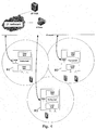
- Fig. 4 illustrates an example network of three base station devices B1, B2, B3 according to the invention which are connected to an IP network, thus enabling VoIP communication with one of the four wireless terminals distributed within the wireless coverage (circles) of each of the base station devices B1, B2, B3. This allows VoIP calls between the wireless terminals and an IP phone or an IP phone switch, an IP PBX.
- the base station device are configured for automatic distribution of system configuration data via IP network so as to allow a user to update the system by updating data in one of the base stations B1, B2, B3 only.
- IP network IP network
- the network of base stations is also flexible, since maybe only the radio transceiver of the base station fails, while still the routing and upper layer facilities can still be used in the network. Also the risk of loosing an on-going communication session is minimal due to the possibility that two or three base station devices may be involved in the lower layer handling of the communication session. Thus, even if the lower layer of one base station fails, another base station may be able to take over its tasks and keep the communication session running. If the upper layer of one base station fails, then the on-going communication session is lost, but upper layer activities, e.g. location registration, can be performed on another base station in the network.
- upper layer activities e.g. location registration
- Fig. 5 illustrates a possible implementation of the routing layer.
- the routing layer has mainly the task of sending connection and session control messages between upper and lower layer software components even when these components are residing in physical separate base stations.
- Establishment of incoming communication sessions is done indirectly by paging the wireless terminal on one of more base stations.
- Paging messages are sent downwards from upper layer to the local lower layer and sent via IP multicast to other base stations.
- IP multicast paging messages the routing layer is sending these downwards to the lower layer and a paging message is broadcasted on the radio transceiver.
- paging messages can be broadcasted on multiple base stations.
- Physical connections between a wireless terminal and the base station are established by the wireless terminal.
- a connection is created using a randomly chosen unassigned PMID (Portable MAC identifier).
- the routing layer "Unassigned switching" will route connection control messages for connections using unassigned PMID to the upper layer in any base station having available resources.
- an upper layer session is created in a basestation and a unique PMID is assigned for addressing the communication with the wireless terminal.
- the PMID is constructed such that a unique basestation identity is included in the PMID.
- connection control messages will include the PMID, and this will allow the "PMID switch” by lookup in a table to send the connection control messages via IP network to basestation in which the upper layer session exists.
- the "Downwards switch” performs lookup in a table containing the mapping between PMID and IP address and forwards connection control messages to the proper lower layer independent of where it physically is located.
- the "Inbound switching" determines whether an incoming message is designated for upper or lower layers.
- the invention provides a wireless base station device for handling wireless communication, e.g. DECT, between a plurality of associated wireless terminals and an IP network.
- the base station device has a radio transceiver, a network interface, and a processor with communication application and a communication session management software.
- the communication session management is arranged to control a communication session with an associated wireless terminal (upper layer management), while wireless communication with said associated wireless terminal involved with said communication session (lower layer) is handled by another base station device.
- the base station can manage separate operation of its upper and lower layers, thereby enabling e.g. hand-over of a session to and from other base stations. This allows self contained single casing base station devices to operate in a network without the need for at central server, and still such network is easy to extend by adding base stations.
Landscapes
- Engineering & Computer Science (AREA)
- Computer Networks & Wireless Communication (AREA)
- Signal Processing (AREA)
- Multimedia (AREA)
- Business, Economics & Management (AREA)
- General Business, Economics & Management (AREA)
- Mobile Radio Communication Systems (AREA)
Claims (15)
- Dispositif station de base sans fil conçu pour traiter la communication sans fil entre une pluralité de terminaux sans fil (T1, T2, T3) associés et un réseau IP, le dispositif comprenant- un émetteur-récepteur radio (RT) conçu pour communiquer sans fil avec la pluralité de terminaux sans fil (T1, T2, T3),- une interface réseau (NI) conçue pour communiquer avec le réseau IP, et- un processeur muni d'un logiciel conçu pour exécuterdans lequel la gestion de session de communication (CSM) est conçue pour contrôler une session de communication avec un terminal sans fil (T1, T2, T3) associé, pendant que la communication par radiofréquence sans fil avec ledit terminal sans fil (T1, T2, T3) associé impliqué dans ladite session de communication est traitée par un dispositif externe (B2, B3) associé,- une application de communication, et- une gestion de session de communication (CSM) pour contrôler des sessions de communication avec la pluralité de terminaux sans fil (T1, T2, T3) associés,
dans lequel une couche inférieure (LL) du dispositif station de base sans fil comprend l'émetteur-récepteur radio (RT), dans lequel une couche supérieure (UL) du dispositif station de base sans fil comprend l'application de communication et la gestion de session de communication (CSM),
caractérisé en ce que
le dispositif station de base sans fil comprend une couche de routage (RL) servant à séparer la couche inférieure (LL) et la couche supérieure (UL) de manière à permettre à la couche supérieure (UL) de traiter des sessions de communication avec des couches inférieures (LL) associées séparées physiquement de la couche supérieure (UL), et
en ce que l'émetteur-récepteur radio (RT), l'interface réseau (NI) et le processeur sont situés dans un même boîtier. - Dispositif selon la revendication 1, dans lequel le dispositif station de base sans fil (B2) est en outre conçu pour traiter la communication par radiofréquence sans fil avec un terminal sans fil associé impliqué dans une session de communication, pendant que ladite session de communication est contrôlée par un dispositif externe (B1) associé.
- Dispositif selon la revendication 1 ou 2, dans lequel le dispositif externe (B1) associé est un dispositif station de base sans fil externe.
- Dispositif selon la revendication 3, dans lequel la couche inférieure (LL) comprend en outre un moyen de traitement pour le codage de données utilisateur.
- Dispositif selon la revendication 4, dans lequel le moyen de traitement pour le codage de données utilisateur comprend le transcodage de données audio.
- Dispositif selon l'une quelconque des revendications précédentes, conçu pour transférer une session de communication en cours avec un terminal sans fil associé vers un dispositif station de base sans fil externe associé.
- Dispositif selon la revendication 6, dans lequel le dispositif est conçu pour recevoir des données utilisateur provenant dudit dispositif station de base sans fil externe et pour relayer les données utilisateur vers le réseau IP en maintenant une adresse IP déjà attribuée à la session de communication avant le transfert.
- Dispositif selon l'une quelconque des revendications précédentes, dans lequel le dispositif est conçu pour recevoir des informations de radiomessagerie provenant du réseau IP, et pour transmettre des informations de radiomessagerie dans un signal sans fil via l'émetteur-récepteur radio (RT), de manière à permettre l'itinérance de la pluralité de terminaux sans fil (T1, T2, T3) associés.
- Dispositif selon l'une quelconque des revendications précédentes, dans lequel le processeur est conçu pour échanger des données de configuration système et des informations d'identité sur la pluralité de terminaux sans fil (T1, T2, T3) associés via le réseau IP.
- Dispositif selon l'une quelconque des revendications précédentes, dans lequel la pluralité de terminaux sans fil (T1, T2, T3) associés comprend une pluralité de combinés mobiles sans fil conçus pour la communication verbale.
- Dispositif selon l'une quelconque des revendications précédentes, dans lequel le dispositif station de base sans fil est conçu pour définir le moment de la synchronisation de l'émetteur-récepteur radio (RT) avec un dispositif station de base sans fil externe associé.
- Dispositif selon l'une quelconque des revendications précédentes, dans lequel le dispositif station de base sans fil est conçu pour attribuer un numéro d'identification sur le réseau IP.
- Dispositif selon l'une quelconque des revendications précédentes, dans lequel l'émetteur-récepteur radio (RT) sans fil est conçu pour communiquer sans fil selon une norme de communication étant l'une des suivantes : DECT/CAT-iq, Bluetooth, WiFi, GSM, LTE, Wimax, 3G et 4G.
- Dispositif selon l'une quelconque des revendications précédentes, dans lequel l'application de communication comprend une application VoIP de manière à permettre au dispositif de traiter la communication VoIP entre des terminaux sans fil (T1, T2, T3) et le réseau IP.
- Système de réseau sans fil comprenant- une pluralité de dispositifs station de base sans fil (B1, B2, B3) selon l'une quelconque des revendications 1 à 14, et- une pluralité de terminaux sans fil (T1, T2, T3) conçus pour communiquer sans fil via l'émetteur-récepteur radio (RT) d'au moins l'un de la pluralité de dispositifs station de base sans fil (B1, B2, B3).
Priority Applications (10)
| Application Number | Priority Date | Filing Date | Title |
|---|---|---|---|
| EP10197291.7A EP2472812B1 (fr) | 2010-12-29 | 2010-12-29 | Architecture VOIP multicellulaire sans fil adaptative |
| JP2013546590A JP2014506055A (ja) | 2010-12-29 | 2011-12-16 | スケーラブルな無線マルチセルVoIPアーキテクチャ |
| CN201180063750.8A CN103348650B (zh) | 2010-12-29 | 2011-12-16 | 可扩展的无线多单元互联网协议电话结构 |
| AU2011351900A AU2011351900B2 (en) | 2010-12-29 | 2011-12-16 | Scalable wireless multicell VoIP architecture |
| PCT/DK2011/050488 WO2012089209A1 (fr) | 2010-12-29 | 2011-12-16 | Architecture voip multicellule sans fil extensible |
| RU2013135401/08A RU2584487C2 (ru) | 2010-12-29 | 2011-12-16 | Масштабируемая беспроводная многоячеистая vоip-архитектура |
| KR1020137019532A KR20140048839A (ko) | 2010-12-29 | 2011-12-16 | 확장 및 축소가 가능한 무선 멀티셀 VoIP 구조 |
| US13/995,632 US9100928B2 (en) | 2010-12-29 | 2011-12-16 | Scalable wireless multicell VoIP architecture |
| CA2858917A CA2858917C (fr) | 2010-12-29 | 2011-12-16 | Architecture voip multicellule sans fil extensible |
| ZA2013/04603A ZA201304603B (en) | 2010-12-29 | 2013-06-21 | Scalable wireless multicell voip architecture |
Applications Claiming Priority (1)
| Application Number | Priority Date | Filing Date | Title |
|---|---|---|---|
| EP10197291.7A EP2472812B1 (fr) | 2010-12-29 | 2010-12-29 | Architecture VOIP multicellulaire sans fil adaptative |
Publications (2)
| Publication Number | Publication Date |
|---|---|
| EP2472812A1 EP2472812A1 (fr) | 2012-07-04 |
| EP2472812B1 true EP2472812B1 (fr) | 2014-02-12 |
Family
ID=44063691
Family Applications (1)
| Application Number | Title | Priority Date | Filing Date |
|---|---|---|---|
| EP10197291.7A Active EP2472812B1 (fr) | 2010-12-29 | 2010-12-29 | Architecture VOIP multicellulaire sans fil adaptative |
Country Status (9)
| Country | Link |
|---|---|
| US (1) | US9100928B2 (fr) |
| EP (1) | EP2472812B1 (fr) |
| JP (1) | JP2014506055A (fr) |
| KR (1) | KR20140048839A (fr) |
| CN (1) | CN103348650B (fr) |
| CA (1) | CA2858917C (fr) |
| RU (1) | RU2584487C2 (fr) |
| WO (1) | WO2012089209A1 (fr) |
| ZA (1) | ZA201304603B (fr) |
Families Citing this family (1)
| Publication number | Priority date | Publication date | Assignee | Title |
|---|---|---|---|---|
| CN111867008B (zh) * | 2020-05-21 | 2023-02-17 | 厦门亿联网络技术股份有限公司 | 一种多模式基站及无绳通信系统 |
Family Cites Families (19)
| Publication number | Priority date | Publication date | Assignee | Title |
|---|---|---|---|---|
| FI98176C (fi) * | 1995-06-07 | 1997-04-25 | Nokia Mobile Phones Ltd | Keskinäisten nopeussovitusten toteutus GSM- ja DECT-järjestelmän välisissä datapalveluissa |
| US5940758A (en) * | 1996-06-28 | 1999-08-17 | Lucent Technologies Inc. | Wireless handset paging utilizing connection endpoint service identifiers |
| ATE370607T1 (de) * | 1999-02-24 | 2007-09-15 | Ericsson Telefon Ab L M | Verfahren und vorrichtung zum vermittlen von anrufen in hybriden sprache/data/internet/schnurlos systemen |
| US6430395B2 (en) * | 2000-04-07 | 2002-08-06 | Commil Ltd. | Wireless private branch exchange (WPBX) and communicating between mobile units and base stations |
| US7035932B1 (en) * | 2000-10-27 | 2006-04-25 | Eric Morgan Dowling | Federated multiprotocol communication |
| US20030125023A1 (en) * | 2001-03-15 | 2003-07-03 | Eyal Fishler | Method and system for providing a wireless terminal communication session integrated with data and voice services |
| US20030148779A1 (en) * | 2001-04-30 | 2003-08-07 | Winphoria Networks, Inc. | System and method of expediting call establishment in mobile communications |
| EP1257132A1 (fr) * | 2001-05-08 | 2002-11-13 | Telefonaktiebolaget L M Ericsson (Publ) | Appareil pour l'integration des téléphones mobile comme terminals de un réseau de communication privé |
| EP1345462A1 (fr) * | 2002-03-02 | 2003-09-17 | Ascom AG | Système de télécommunication sans fils et procédé d'operation correspondant |
| US6879600B1 (en) * | 2002-06-03 | 2005-04-12 | Sprint Spectrum, L.P. | Method and system for intersystem wireless communication session arbitration |
| KR100800879B1 (ko) * | 2004-03-05 | 2008-02-04 | 삼성전자주식회사 | 무선 통신 시스템의 분리형 매체 억세스 제어 프로토콜 구조와 이를 이용한 데이터 송수신 방법 및 핸드 오버 방법과 그 시스템 |
| US7729700B2 (en) * | 2004-06-07 | 2010-06-01 | Nokia Corporation | Vertical network handovers |
| US20070280252A1 (en) * | 2006-06-02 | 2007-12-06 | Inventec Multimedia & Telecom Corporation | System and method of realizing voice over internet protocol by means of digital enhanced cordless telecommunication |
| US20080085741A1 (en) * | 2006-10-10 | 2008-04-10 | Sony Ericsson Mobile Communications Ab | Method for providing an alert signal |
| US20080117076A1 (en) * | 2006-11-16 | 2008-05-22 | Arthur John Klaus | System and method for conducting bi-directional communication sessions with utility meters from a mobile device |
| JP4989450B2 (ja) * | 2007-04-18 | 2012-08-01 | 京セラ株式会社 | 無線通信システム、基地局および無線通信方法 |
| CN101355738B (zh) * | 2007-07-25 | 2011-07-13 | 中兴通讯股份有限公司 | 一种Abis接口不连续传输模式的语音传输装置及方法 |
| WO2010088926A1 (fr) * | 2009-02-09 | 2010-08-12 | Nokia Siemens Networks Oy | Commutation de couche liaison pour une dérivation locale |
| BRPI1014149A2 (pt) * | 2009-06-29 | 2019-09-24 | Research In Motion Ltd | sistema e método para serviço de voz em um sistema de pacote evoluído. |
-
2010
- 2010-12-29 EP EP10197291.7A patent/EP2472812B1/fr active Active
-
2011
- 2011-12-16 RU RU2013135401/08A patent/RU2584487C2/ru active
- 2011-12-16 KR KR1020137019532A patent/KR20140048839A/ko not_active Ceased
- 2011-12-16 CN CN201180063750.8A patent/CN103348650B/zh active Active
- 2011-12-16 JP JP2013546590A patent/JP2014506055A/ja active Pending
- 2011-12-16 CA CA2858917A patent/CA2858917C/fr active Active
- 2011-12-16 WO PCT/DK2011/050488 patent/WO2012089209A1/fr not_active Ceased
- 2011-12-16 US US13/995,632 patent/US9100928B2/en active Active
-
2013
- 2013-06-21 ZA ZA2013/04603A patent/ZA201304603B/en unknown
Also Published As
| Publication number | Publication date |
|---|---|
| CA2858917C (fr) | 2019-02-12 |
| CN103348650A (zh) | 2013-10-09 |
| RU2584487C2 (ru) | 2016-05-20 |
| EP2472812A1 (fr) | 2012-07-04 |
| AU2011351900A1 (en) | 2013-07-18 |
| CN103348650B (zh) | 2015-08-26 |
| US9100928B2 (en) | 2015-08-04 |
| US20130272208A1 (en) | 2013-10-17 |
| WO2012089209A1 (fr) | 2012-07-05 |
| CA2858917A1 (fr) | 2013-07-05 |
| JP2014506055A (ja) | 2014-03-06 |
| ZA201304603B (en) | 2014-03-26 |
| RU2013135401A (ru) | 2015-02-10 |
| KR20140048839A (ko) | 2014-04-24 |
Similar Documents
| Publication | Publication Date | Title |
|---|---|---|
| US11095645B2 (en) | Virtualization of the evolved packet core to create a local EPC | |
| CN102695292B (zh) | 用于移动网络设备间通信的系统和方法 | |
| JP5272536B2 (ja) | 呼中継方法および呼中継システム | |
| KR101057815B1 (ko) | 터널링 기반 이동성 지원 장치 및 방법 | |
| KR101514955B1 (ko) | Wifi-dect 무선 원격통신 네트워크 내의 단말과 관련된 무선 액세스 포인트를 변경하는 방법 | |
| US7395065B2 (en) | Routing calls to facilitate call handover | |
| MX2008014451A (es) | Metodo y aparato para soportar una llamada de emergencia en una red de area metropolitana inalambrica. | |
| WO2007043201A1 (fr) | Procédé de sélection de réseau d’accès | |
| EP2472812B1 (fr) | Architecture VOIP multicellulaire sans fil adaptative | |
| AU2011351900B2 (en) | Scalable wireless multicell VoIP architecture | |
| JP2012156796A (ja) | 通信システム、通信端末、ゲートウェイ、通信方法及びプログラム | |
| US8320295B2 (en) | Mobile IP control system, mobile IP control method, and mobile IP control program | |
| KR100845229B1 (ko) | 유무선통합 기업 통신망 환경에서의 CUG/VPN기반모바일 VoIP 서비스 시스템 | |
| JP2012507227A (ja) | 通信装置及びサーバ並びにこれらのための方法及びコンピュータプログラム | |
| US20250393038A1 (en) | Systems for extending range of a base station via a backhaul network | |
| JP2005253024A (ja) | ローミングシステム、ローミング方法及び移動端末 | |
| GB2413733A (en) | Voice over internet communications | |
| JP2011250132A (ja) | 無線基地局装置、無線基地局システムおよびハンドオーバ制御の通信経路確立方法 | |
| JP2015146539A (ja) | 無線通信端末および移動体無線通信システムへの接続方法 |
Legal Events
| Date | Code | Title | Description |
|---|---|---|---|
| AK | Designated contracting states |
Kind code of ref document: A1 Designated state(s): AL AT BE BG CH CY CZ DE DK EE ES FI FR GB GR HR HU IE IS IT LI LT LU LV MC MK MT NL NO PL PT RO RS SE SI SK SM TR |
|
| AX | Request for extension of the european patent |
Extension state: BA ME |
|
| PUAI | Public reference made under article 153(3) epc to a published international application that has entered the european phase |
Free format text: ORIGINAL CODE: 0009012 |
|
| RAP1 | Party data changed (applicant data changed or rights of an application transferred) |
Owner name: RTX A/S |
|
| 17P | Request for examination filed |
Effective date: 20121030 |
|
| 17Q | First examination report despatched |
Effective date: 20130315 |
|
| REG | Reference to a national code |
Ref country code: DE Ref legal event code: R079 Ref document number: 602010013485 Country of ref document: DE Free format text: PREVIOUS MAIN CLASS: H04L0029060000 Ipc: H04W0036000000 |
|
| GRAP | Despatch of communication of intention to grant a patent |
Free format text: ORIGINAL CODE: EPIDOSNIGR1 |
|
| RIC1 | Information provided on ipc code assigned before grant |
Ipc: H04W 36/00 20090101AFI20130902BHEP |
|
| INTG | Intention to grant announced |
Effective date: 20130919 |
|
| GRAS | Grant fee paid |
Free format text: ORIGINAL CODE: EPIDOSNIGR3 |
|
| GRAA | (expected) grant |
Free format text: ORIGINAL CODE: 0009210 |
|
| AK | Designated contracting states |
Kind code of ref document: B1 Designated state(s): AL AT BE BG CH CY CZ DE DK EE ES FI FR GB GR HR HU IE IS IT LI LT LU LV MC MK MT NL NO PL PT RO RS SE SI SK SM TR |
|
| REG | Reference to a national code |
Ref country code: GB Ref legal event code: FG4D |
|
| REG | Reference to a national code |
Ref country code: CH Ref legal event code: EP |
|
| REG | Reference to a national code |
Ref country code: AT Ref legal event code: REF Ref document number: 652593 Country of ref document: AT Kind code of ref document: T Effective date: 20140215 |
|
| REG | Reference to a national code |
Ref country code: IE Ref legal event code: FG4D |
|
| REG | Reference to a national code |
Ref country code: DE Ref legal event code: R096 Ref document number: 602010013485 Country of ref document: DE Effective date: 20140327 |
|
| REG | Reference to a national code |
Ref country code: NL Ref legal event code: T3 |
|
| REG | Reference to a national code |
Ref country code: SE Ref legal event code: TRGR |
|
| REG | Reference to a national code |
Ref country code: AT Ref legal event code: MK05 Ref document number: 652593 Country of ref document: AT Kind code of ref document: T Effective date: 20140212 |
|
| REG | Reference to a national code |
Ref country code: LT Ref legal event code: MG4D |
|
| PG25 | Lapsed in a contracting state [announced via postgrant information from national office to epo] |
Ref country code: NO Free format text: LAPSE BECAUSE OF FAILURE TO SUBMIT A TRANSLATION OF THE DESCRIPTION OR TO PAY THE FEE WITHIN THE PRESCRIBED TIME-LIMIT Effective date: 20140512 Ref country code: LT Free format text: LAPSE BECAUSE OF FAILURE TO SUBMIT A TRANSLATION OF THE DESCRIPTION OR TO PAY THE FEE WITHIN THE PRESCRIBED TIME-LIMIT Effective date: 20140212 Ref country code: IS Free format text: LAPSE BECAUSE OF FAILURE TO SUBMIT A TRANSLATION OF THE DESCRIPTION OR TO PAY THE FEE WITHIN THE PRESCRIBED TIME-LIMIT Effective date: 20140612 |
|
| PG25 | Lapsed in a contracting state [announced via postgrant information from national office to epo] |
Ref country code: PT Free format text: LAPSE BECAUSE OF FAILURE TO SUBMIT A TRANSLATION OF THE DESCRIPTION OR TO PAY THE FEE WITHIN THE PRESCRIBED TIME-LIMIT Effective date: 20140612 Ref country code: AT Free format text: LAPSE BECAUSE OF FAILURE TO SUBMIT A TRANSLATION OF THE DESCRIPTION OR TO PAY THE FEE WITHIN THE PRESCRIBED TIME-LIMIT Effective date: 20140212 Ref country code: CY Free format text: LAPSE BECAUSE OF FAILURE TO SUBMIT A TRANSLATION OF THE DESCRIPTION OR TO PAY THE FEE WITHIN THE PRESCRIBED TIME-LIMIT Effective date: 20140212 Ref country code: FI Free format text: LAPSE BECAUSE OF FAILURE TO SUBMIT A TRANSLATION OF THE DESCRIPTION OR TO PAY THE FEE WITHIN THE PRESCRIBED TIME-LIMIT Effective date: 20140212 Ref country code: ES Free format text: LAPSE BECAUSE OF FAILURE TO SUBMIT A TRANSLATION OF THE DESCRIPTION OR TO PAY THE FEE WITHIN THE PRESCRIBED TIME-LIMIT Effective date: 20140212 |
|
| PG25 | Lapsed in a contracting state [announced via postgrant information from national office to epo] |
Ref country code: RS Free format text: LAPSE BECAUSE OF FAILURE TO SUBMIT A TRANSLATION OF THE DESCRIPTION OR TO PAY THE FEE WITHIN THE PRESCRIBED TIME-LIMIT Effective date: 20140212 Ref country code: BE Free format text: LAPSE BECAUSE OF FAILURE TO SUBMIT A TRANSLATION OF THE DESCRIPTION OR TO PAY THE FEE WITHIN THE PRESCRIBED TIME-LIMIT Effective date: 20140212 Ref country code: LV Free format text: LAPSE BECAUSE OF FAILURE TO SUBMIT A TRANSLATION OF THE DESCRIPTION OR TO PAY THE FEE WITHIN THE PRESCRIBED TIME-LIMIT Effective date: 20140212 Ref country code: HR Free format text: LAPSE BECAUSE OF FAILURE TO SUBMIT A TRANSLATION OF THE DESCRIPTION OR TO PAY THE FEE WITHIN THE PRESCRIBED TIME-LIMIT Effective date: 20140212 |
|
| PG25 | Lapsed in a contracting state [announced via postgrant information from national office to epo] |
Ref country code: RO Free format text: LAPSE BECAUSE OF FAILURE TO SUBMIT A TRANSLATION OF THE DESCRIPTION OR TO PAY THE FEE WITHIN THE PRESCRIBED TIME-LIMIT Effective date: 20140212 Ref country code: CZ Free format text: LAPSE BECAUSE OF FAILURE TO SUBMIT A TRANSLATION OF THE DESCRIPTION OR TO PAY THE FEE WITHIN THE PRESCRIBED TIME-LIMIT Effective date: 20140212 Ref country code: DK Free format text: LAPSE BECAUSE OF FAILURE TO SUBMIT A TRANSLATION OF THE DESCRIPTION OR TO PAY THE FEE WITHIN THE PRESCRIBED TIME-LIMIT Effective date: 20140212 Ref country code: EE Free format text: LAPSE BECAUSE OF FAILURE TO SUBMIT A TRANSLATION OF THE DESCRIPTION OR TO PAY THE FEE WITHIN THE PRESCRIBED TIME-LIMIT Effective date: 20140212 |
|
| REG | Reference to a national code |
Ref country code: DE Ref legal event code: R097 Ref document number: 602010013485 Country of ref document: DE |
|
| PG25 | Lapsed in a contracting state [announced via postgrant information from national office to epo] |
Ref country code: PL Free format text: LAPSE BECAUSE OF FAILURE TO SUBMIT A TRANSLATION OF THE DESCRIPTION OR TO PAY THE FEE WITHIN THE PRESCRIBED TIME-LIMIT Effective date: 20140212 Ref country code: SK Free format text: LAPSE BECAUSE OF FAILURE TO SUBMIT A TRANSLATION OF THE DESCRIPTION OR TO PAY THE FEE WITHIN THE PRESCRIBED TIME-LIMIT Effective date: 20140212 |
|
| PLBE | No opposition filed within time limit |
Free format text: ORIGINAL CODE: 0009261 |
|
| STAA | Information on the status of an ep patent application or granted ep patent |
Free format text: STATUS: NO OPPOSITION FILED WITHIN TIME LIMIT |
|
| 26N | No opposition filed |
Effective date: 20141113 |
|
| REG | Reference to a national code |
Ref country code: DE Ref legal event code: R097 Ref document number: 602010013485 Country of ref document: DE Effective date: 20141113 |
|
| PG25 | Lapsed in a contracting state [announced via postgrant information from national office to epo] |
Ref country code: IT Free format text: LAPSE BECAUSE OF FAILURE TO SUBMIT A TRANSLATION OF THE DESCRIPTION OR TO PAY THE FEE WITHIN THE PRESCRIBED TIME-LIMIT Effective date: 20140212 |
|
| PG25 | Lapsed in a contracting state [announced via postgrant information from national office to epo] |
Ref country code: SI Free format text: LAPSE BECAUSE OF FAILURE TO SUBMIT A TRANSLATION OF THE DESCRIPTION OR TO PAY THE FEE WITHIN THE PRESCRIBED TIME-LIMIT Effective date: 20140212 |
|
| PG25 | Lapsed in a contracting state [announced via postgrant information from national office to epo] |
Ref country code: LU Free format text: LAPSE BECAUSE OF FAILURE TO SUBMIT A TRANSLATION OF THE DESCRIPTION OR TO PAY THE FEE WITHIN THE PRESCRIBED TIME-LIMIT Effective date: 20141229 |
|
| REG | Reference to a national code |
Ref country code: CH Ref legal event code: PL |
|
| REG | Reference to a national code |
Ref country code: IE Ref legal event code: MM4A |
|
| PG25 | Lapsed in a contracting state [announced via postgrant information from national office to epo] |
Ref country code: LI Free format text: LAPSE BECAUSE OF NON-PAYMENT OF DUE FEES Effective date: 20141231 Ref country code: IE Free format text: LAPSE BECAUSE OF NON-PAYMENT OF DUE FEES Effective date: 20141229 Ref country code: CH Free format text: LAPSE BECAUSE OF NON-PAYMENT OF DUE FEES Effective date: 20141231 |
|
| REG | Reference to a national code |
Ref country code: FR Ref legal event code: PLFP Year of fee payment: 6 |
|
| PG25 | Lapsed in a contracting state [announced via postgrant information from national office to epo] |
Ref country code: SM Free format text: LAPSE BECAUSE OF FAILURE TO SUBMIT A TRANSLATION OF THE DESCRIPTION OR TO PAY THE FEE WITHIN THE PRESCRIBED TIME-LIMIT Effective date: 20140212 |
|
| PG25 | Lapsed in a contracting state [announced via postgrant information from national office to epo] |
Ref country code: MC Free format text: LAPSE BECAUSE OF FAILURE TO SUBMIT A TRANSLATION OF THE DESCRIPTION OR TO PAY THE FEE WITHIN THE PRESCRIBED TIME-LIMIT Effective date: 20140212 |
|
| PG25 | Lapsed in a contracting state [announced via postgrant information from national office to epo] |
Ref country code: GR Free format text: LAPSE BECAUSE OF FAILURE TO SUBMIT A TRANSLATION OF THE DESCRIPTION OR TO PAY THE FEE WITHIN THE PRESCRIBED TIME-LIMIT Effective date: 20140513 Ref country code: BG Free format text: LAPSE BECAUSE OF FAILURE TO SUBMIT A TRANSLATION OF THE DESCRIPTION OR TO PAY THE FEE WITHIN THE PRESCRIBED TIME-LIMIT Effective date: 20140212 |
|
| PG25 | Lapsed in a contracting state [announced via postgrant information from national office to epo] |
Ref country code: TR Free format text: LAPSE BECAUSE OF FAILURE TO SUBMIT A TRANSLATION OF THE DESCRIPTION OR TO PAY THE FEE WITHIN THE PRESCRIBED TIME-LIMIT Effective date: 20140212 Ref country code: MT Free format text: LAPSE BECAUSE OF FAILURE TO SUBMIT A TRANSLATION OF THE DESCRIPTION OR TO PAY THE FEE WITHIN THE PRESCRIBED TIME-LIMIT Effective date: 20140212 Ref country code: HU Free format text: LAPSE BECAUSE OF FAILURE TO SUBMIT A TRANSLATION OF THE DESCRIPTION OR TO PAY THE FEE WITHIN THE PRESCRIBED TIME-LIMIT; INVALID AB INITIO Effective date: 20101229 |
|
| REG | Reference to a national code |
Ref country code: FR Ref legal event code: PLFP Year of fee payment: 7 |
|
| REG | Reference to a national code |
Ref country code: FR Ref legal event code: PLFP Year of fee payment: 8 |
|
| PG25 | Lapsed in a contracting state [announced via postgrant information from national office to epo] |
Ref country code: MK Free format text: LAPSE BECAUSE OF FAILURE TO SUBMIT A TRANSLATION OF THE DESCRIPTION OR TO PAY THE FEE WITHIN THE PRESCRIBED TIME-LIMIT Effective date: 20140212 |
|
| PG25 | Lapsed in a contracting state [announced via postgrant information from national office to epo] |
Ref country code: AL Free format text: LAPSE BECAUSE OF FAILURE TO SUBMIT A TRANSLATION OF THE DESCRIPTION OR TO PAY THE FEE WITHIN THE PRESCRIBED TIME-LIMIT Effective date: 20140212 |
|
| P01 | Opt-out of the competence of the unified patent court (upc) registered |
Effective date: 20230524 |
|
| PGFP | Annual fee paid to national office [announced via postgrant information from national office to epo] |
Ref country code: DE Payment date: 20251211 Year of fee payment: 16 |
|
| PGFP | Annual fee paid to national office [announced via postgrant information from national office to epo] |
Ref country code: GB Payment date: 20251219 Year of fee payment: 16 |
|
| PGFP | Annual fee paid to national office [announced via postgrant information from national office to epo] |
Ref country code: NL Payment date: 20251219 Year of fee payment: 16 Ref country code: FR Payment date: 20251222 Year of fee payment: 16 |
|
| PGFP | Annual fee paid to national office [announced via postgrant information from national office to epo] |
Ref country code: SE Payment date: 20251219 Year of fee payment: 16 |