EP2472908A1 - Dispositif de prothèse auditive - Google Patents
Dispositif de prothèse auditive Download PDFInfo
- Publication number
- EP2472908A1 EP2472908A1 EP10814638A EP10814638A EP2472908A1 EP 2472908 A1 EP2472908 A1 EP 2472908A1 EP 10814638 A EP10814638 A EP 10814638A EP 10814638 A EP10814638 A EP 10814638A EP 2472908 A1 EP2472908 A1 EP 2472908A1
- Authority
- EP
- European Patent Office
- Prior art keywords
- hearing aid
- notification
- communication
- hearing
- sound
- Prior art date
- Legal status (The legal status is an assumption and is not a legal conclusion. Google has not performed a legal analysis and makes no representation as to the accuracy of the status listed.)
- Withdrawn
Links
Images


Classifications
-
- H—ELECTRICITY
- H04—ELECTRIC COMMUNICATION TECHNIQUE
- H04R—LOUDSPEAKERS, MICROPHONES, GRAMOPHONE PICK-UPS OR LIKE ACOUSTIC ELECTROMECHANICAL TRANSDUCERS; ELECTRIC HEARING AIDS; PUBLIC ADDRESS SYSTEMS
- H04R25/00—Electric hearing aids
- H04R25/55—Electric hearing aids using an external connection, either wireless or wired
- H04R25/552—Binaural
-
- H—ELECTRICITY
- H04—ELECTRIC COMMUNICATION TECHNIQUE
- H04R—LOUDSPEAKERS, MICROPHONES, GRAMOPHONE PICK-UPS OR LIKE ACOUSTIC ELECTROMECHANICAL TRANSDUCERS; ELECTRIC HEARING AIDS; PUBLIC ADDRESS SYSTEMS
- H04R25/00—Electric hearing aids
- H04R25/30—Monitoring or testing of hearing aids, e.g. functioning, settings, battery power
- H04R25/305—Self-monitoring or self-testing
Definitions
- the present invention relates to a hearing aid device in which two hearing aids used on the two ears communicate with each other.
- Binaural type of hearing aid that has been gaining popularity in recent years is mounted on both ears, and various modes are synchronized between the hearing aids through wireless communication.
- Patent Literature 1 Japanese Laid-Open Patent Application 2007-336308
- the technique disclosed in the above-mentioned publication is for operating with just one hearing aid when communication cannot be established. Therefore, the user cannot be notified of a malfunction in one of the hearing aids, and the problem of inconvenience cannot be solved.
- the hearing aid device of the present invention comprises first and second hearing aids separately mounted on the two ears of the user.
- the first and second hearing aids each have a main body, a sound collector, a hearing aid processor, a speech output section, a communication section, a notification controller, and a notification synthesizer.
- the main body has a mounting shape that conforms to the shape of the user's ear.
- the sound collector takes in ambient sound from around the main body.
- the hearing aid processor subjects the ambient sound taken in by the sound collector to hearing aid processing.
- the speech output section outputs to outside the main body the sound that has been processed by the hearing aid processor.
- the communication section communicates between the first and second hearing aids.
- the notification controller decides the communication state between the first and second hearing aids.
- the notification synthesizer that alerts the user according to the decision result for the communication state by the notification controller.
- the hearing aid device of the present invention comprises first and second hearing aids separately mounted on the two ears of the user.
- the first and second hearing aids each have a main body, a sound collector, a hearing aid processor, a speech output section, a communication section, a remaining battery charge transmission section, a notification controller, and a notification synthesizer.
- the main body has a mounting shape that conforms to the shape of the user's ear.
- the sound collector that takes in ambient sound from around the main body.
- the hearing aid processor subjects the ambient sound taken in by the sound collector to hearing aid processing.
- the speech output section outputs to outside the main body the sound that has been processed by the hearing aid processor.
- the communication section communicates between the first and second hearing aids.
- the remaining battery charge transmission section notifies the first or the second hearing aid that the battery has died in the second or the first hearing aid.
- the notification controller determines the communication state between the first and second hearing aids and the state of the remaining battery charge of the first and second hearing aids.
- the notification synthesizer alerts the user to the determination result for the communication state by the notification controller, and at the first or the second hearing aid whose battery has not died according, on the basis of the determination result for the remaining battery charge of the second or first hearing aid.
- a convenient hearing aid device can be provided because the user can be reliably advised that the power has been properly switched on to both hearing aids, and that the power to one hearing aid has been blocked due to a low battery during use.
- the hearing aid on the side where the battery is not dead will be called the first hearing aid
- the hearing aid on the side with the dead battery will be called the second hearing aid
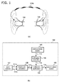
- FIG. 1 shows the configuration of the hearing aid device in this embodiment.
- FIG. 1a is a concept diagram of when the two hearing aids 100 (first and second hearing aids) constituting the hearing aid device have been mounted to the ears.
- FIG. 1b is a block diagram of the configuration of the hearing aids 100.
- the hearing aid device in this embodiment comprises the two hearing aids 100, 100, which are mounted one each on the two ears.
- each hearing aid 100 has a sound collector 101, a hearing aid processor 102, a notification controller 103, a notification synthesizer 104, a communication section 105, and a speech output section 106.
- the two hearing aids 100, 100 have exactly the same configuration, and are in a completely equal relationship, with neither being inferior to the other.
- the hearing aids 100, 100 are constantly exchanging signals with each other via wireless radio waves 110a.
- FIG. 1b The various elements shown in FIG. 1b will now be described in detail.
- the sound collector 101 includes a sound hole (not shown) provided to the main body of the hearing aid 100, and a microphone (not shown) that collects ambient sound that comes in through the sound hole.
- the microphone converts the collected acoustic signals into analog electrical signals and outputs them.
- the sound collectors 101 are provided with two pairs of sound hole and microphone in order to have directionality, and each output an analog input signal 111a and an analog input signal 111b.
- the hearing aid processors 102 subject the analog input signals 111a and 111b outputted from the sound collectors 101 to hearing aid processing, and adjust the volume to suit the hearing characteristics of the user, after which the products are outputted as analog hearing aid signals 111 to the notification synthesizers 104.
- FIG. 2 is a block diagram of the hearing aid processor 102.
- the hearing aid processor 102 includes an A/D (analog to digital) converter 201, a directionality synthesizer 202, a frequency analyzer 203, a power calculator 204, a gain controller 205, a gain adjuster 206, a frequency synthesizer 207, and a D/A (digital to analog) converter 208.
- A/D analog to digital
- the A/D converters 201 digitally sample the analog input signals 111a and 111b outputted from the sound collectors 101, and output the products as digital input signals 210a and 210b to the directionality synthesizers 202.
- the directionality synthesizers 202 magnify sound coming from a specific direction with respect to the user, and reduce sound from other directions. Specifically, they process and synthesize the digital input signals 210a and 210b so as to match the directionality of the hearing aids 100 in a specific direction. The synthesized signal is outputted as a synthesized signal 211 to the frequency analyzers 203.
- the directionality synthesizers 202 have a plurality of adaptive filters and adders, and by varying the computation coefficients thereof, it is possible to match the directionality to a desired orientation, or to achieve a non-directional state in which the sound can be heard equally in all directions.
- the frequency analyzers 203 convert the synthesized signal 211 inputted in time series from signals for a time region into signals for a frequency region, divide these into a plurality of frequency bands, and output them as a frequency signal group 212. Methods that can be employed to this end include dividing the result of Fourier transformation, and a sub-band division method.
- This division is performed by splitting the frequency handled by the hearing aids 100, 100 into a plurality of segments from the upper limit to the lower limit. For example, if the hearing aids 100, 100 handle ten channels (or ten bands), the frequency region is divided in ten by the frequency analyzers 203. The frequency signals are outputted for each of the frequency bands. The frequency analyzers 203 output these ten frequency signals as the frequency signal group 212.
- the power calculators 204 calculate the power level for each frequency signal of the various bands of the frequency signal group 212 outputted from the frequency analyzers 203.
- the term "power level” here is the magnitude of the electrical power of the signals inputted to the frequency analyzers 203, and is correlated with the sound pressure level of the acoustic signals inputted to the sound collectors 101. Specifically, the lower is the sound pressure level inputted to the sound collectors 101, the higher is the power level, and the higher is the sound pressure level, the lower is the power level.
- the power level is found by taking the sum of squares for the real number section and the imaginary number section for every frequency signal in each band. The power level calculated for each band is outputted as a power level group 112 to the gain controllers 205.
- the gain controllers 205 decide the gain with respect to the frequency signal for each band on the basis of the power level group 112.
- a gain table is used to decide the gain.
- the dynamic range of hearing varies from one user to the next, and nonlinear gain adjustment suited to a given user is necessary for the sound pressure level of an inputted acoustic signal.
- a gain table is produced that sets out the gain characteristics required for the user, which have been found ahead of time by audiogram or the like, for every inputted sound pressure level, that is, power level.
- the gain controllers 205 comprise this gain table for all frequency bands, and the corresponding gain is decided by referring to a gain table when the power level group 112 is inputted. These values are outputted as a gain control signal group 213 to the gain adjusters 206.
- the gain adjusters 206 perform gain computation for the frequency signal group 212, which is a group of frequency signals for each band, on the basis of the gain control signal group 213, and perform gain adjustment on the frequency signals.
- the frequency signals that have undergone gain adjustment are outputted as an adjusted frequency signal group 214 to the frequency synthesizers 207.
- the frequency synthesizers 207 combine the adjusted frequency signal groups 214 composed of ten divided frequency signals and convert from signals for a frequency region into signals for a time region.
- the frequency synthesis is accomplished, for example by reverse Fourier transformation when the frequency analysis is Fourier transformation, and by sub-band synthesis when it is sub-band division.
- the signals that have undergone frequency synthesis are outputted as digital hearing aid signals 215 to the D/A (digital to analog) converters 208.
- the D/A converters 208 perform the reverse conversion from that of the A/D converters 201, and convert the digital hearing aid signals 215, which are digital signals, into the hearing aid signals 111, which are analog signals.
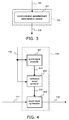
- FIG. 3 is a block diagram of the notification controller 103.
- the notification controller 103 shown in FIG. 3 includes a communication establishment determination section 301.
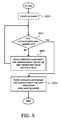
- FIG. 5 is a flowchart of the flow of processing of the communication section 105.
- the communication section 105 of one of the hearing aids (the first hearing aid) 100 attempts to make a communication connection to begin communication with the communication section 105 of the other hearing aid (the second hearing aid) 100.
- communication section 105 of the first hearing aid 100 notifies the communication establishment determination section 301 of the current communication establishment situation in the form of a communication status signal 115.
- the communication establishment determination section 301 monitors the establishment of this communication connection (S001), and if communication has yet to be established, a signal of "0," which indicates that communication has yet to be established, is sent to the notification synthesizer 104 (S002). Upon receiving this notification, the notification synthesizer 104 generates a warning sound.
- the communication establishment determination section 301 sends a signal of "1," which indicates that communication has been established, as a notification to the notification synthesizer 104 (S003). Upon receiving this notification, the notification synthesizer 104 stops the warning sound.
- a warning sound is generated, but this is not the only option.
- a step in which iterations are counted by a counter may be provided in between S001 and S002, and a warning sound generated only when the count of times when it is determined that communication has not been established exceeds a specific count. If this is done, it avoids accidental generation of a warning sound in events such as when the power is on to the second hearing aid 100, but the communication status just happens to be poor, and radio waves cannot be received form the first hearing aid 100. As a result, a warning sound can be generated only in cases when a warning is really necessary.
- FIG. 4 is a block diagram of the notification synthesizer 104.
- the notification synthesizer 104 has a sound signal producer 501, a notification sound controller 502, and a sound signal synthesizer 503.
- the sound signal producer 501 produces a specific sound upon receipt of a signal of "0" as the communication establishment signal 116, that is, when notified that communication has yet to be established.
- the term "specific sound” here is a beeping sound that is repeated at a short interval.
- the sound signal producer 501 outputs this specific sound as a specific sound signal 511 to the notification sound controller 502.
- the specific sound signal 511 is an analog signal.
- the notification sound controller 502 outputs the specific sound signal 511 outputted from the sound signal producer 501, as a notification sound signal 512 to the sound signal synthesizer 503 upon receipt of a signal of "0" as the communication establishment signal 116.
- the sound signal producer 501 ends the production of sound.
- the notification sound controller 502 then stops the output of the notification sound signal 512.
- the sound signal synthesizer 503 uses a multiplier to superimpose the hearing aid signal 111 outputted from the hearing aid processor 102 and the notification sound signal 512 outputted from the notification sound controller 502, and outputs the result as a synthesized hearing aid signal 118 to the speech output section 106.
- the sound signal producer 501 may end the production of the specific sound signal 511.
- the user can be reliably notified of whether or not the power has been turned on to the first and second hearing aids 100, 100. Accordingly, if necessary, the user can be reliably instructed to replace the battery. As a result, the user is prevented from continuing to use the hearing aid device when a battery is dead, which means that a hearing aid device can be provided which is more convenient to use than in the past.
- FIG. 6 is a block diagram of the configuration of a pair of (left and right) first and second hearing aids 400, 400 included in the hearing aid device pertaining to another embodiment of the present invention.
- This embodiment differs from Embodiment 1 above in that notification controller 407 and a remaining battery charge transmission section 408 are added, but the rest of the configuration and operation are the same as in Embodiment 1, so those sections will be numbered the same and not described again.
- FIG. 7 is a block diagram of the configuration of the notification controller 407.
- the difference between the notification controller 407 and the notification controller 103 in Embodiment 1 above is that a battery state detector 302 is added.
- the second hearing aid 400 which is the one that has stopped functioning due to a dead battery, emits a warning sound itself.
- the second hearing aid 400 that has stopped functioning sends the first hearing aid 400 a function stop signal 117 from the remaining battery charge transmission section 408 to the effect that its function has stopped due to battery failure.
- the battery state detector 302 recognizes that the second hearing aid 400 is in a dead battery state. After this, if the second hearing aid 400 has actually stopped functioning because of a dead battery, the first hearing aid 400 recognizes that communication has been blocked by the communication establishment determination section 301, and concludes from this information that power to the second hearing aid 400 has actually been blocked due to a dead battery.
- the first hearing aid 400 periodically sends a communication establishment signal 116 to the notification synthesizer 104, and the notification synthesizer 104 emits a warning sound, until the communication establishment determination section 301 recognizes that communication has once again been established.
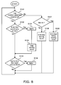
- FIG. 8 is a flowchart of the flow of processing by the notification controller 407.
- the notification controller 407 has decided in S101 that communication has been established, then whether or not a warning sound is being emitted is confirmed (S102).
- the purpose of this is to decide whether or not the communication state has been restored after a communication interruption.
- the notification controller 407 initializes the variable Bat to "0" (S104). This is because if the initial value of the variable Bat is set to "0,” then if a communication interruption should suddenly occur in the future, it can be recognized as being caused by some kind of problem. After the variable Bat has been set to an initial value of "0,” the warning sound is stopped (S 105).
- the notification controller 407 confirms whether or not the function stop signal 117 has been received via the communication section 105 (S103). If a function stop signal has been received, the notification controller 407 sets the variable Bat to "1" (S106). Consequently, if a communication interruption should occur subsequently, it can be recognized that the second hearing aid 400 has a dead battery.
- the hearing aid device of this embodiment even if the second hearing aid 400 should stop functioning during its use due to a dead battery, the fact that the second hearing aid 400 side is in a dead battery state is conveyed to the first hearing aid 400, which periodically emits a warning sound to reliably alert the user to the dead battery. As a result, the user will not just keep using the second hearing aid 400 that has stopped functioning because of a dead battery, and will instead be sure to replace the battery, so a hearing aid device that is more convenient to use can be provided.
- the hearing aid device pertaining to the present invention reliably ensures that the power is properly switched on to first and second hearing aids, and notifies the user when one of the hearing aids has stopped function due to a dead battery, and is therefore useful as a binaural type of hearing aid that is more convenient to use.
Landscapes
- Engineering & Computer Science (AREA)
- Health & Medical Sciences (AREA)
- General Health & Medical Sciences (AREA)
- Otolaryngology (AREA)
- Neurosurgery (AREA)
- Physics & Mathematics (AREA)
- Acoustics & Sound (AREA)
- Signal Processing (AREA)
- Computer Networks & Wireless Communication (AREA)
- Telephone Function (AREA)
- Charge And Discharge Circuits For Batteries Or The Like (AREA)
Applications Claiming Priority (2)
| Application Number | Priority Date | Filing Date | Title |
|---|---|---|---|
| JP2009236388 | 2009-10-13 | ||
| PCT/JP2010/005966 WO2011045905A1 (fr) | 2009-10-13 | 2010-10-05 | Dispositif de prothèse auditive |
Publications (2)
| Publication Number | Publication Date |
|---|---|
| EP2472908A1 true EP2472908A1 (fr) | 2012-07-04 |
| EP2472908A4 EP2472908A4 (fr) | 2013-10-16 |
Family
ID=43875961
Family Applications (1)
| Application Number | Title | Priority Date | Filing Date |
|---|---|---|---|
| EP10814638.2A Withdrawn EP2472908A4 (fr) | 2009-10-13 | 2010-10-05 | Dispositif de prothèse auditive |
Country Status (5)
| Country | Link |
|---|---|
| US (1) | US8532318B2 (fr) |
| EP (1) | EP2472908A4 (fr) |
| JP (1) | JP5439476B2 (fr) |
| CN (1) | CN202135319U (fr) |
| WO (1) | WO2011045905A1 (fr) |
Families Citing this family (11)
| Publication number | Priority date | Publication date | Assignee | Title |
|---|---|---|---|---|
| JP5090585B1 (ja) * | 2009-10-19 | 2012-12-05 | ヴェーデクス・アクティーセルスカプ | ロスト・パートナー機能を備える補聴器システム |
| JP6019553B2 (ja) | 2011-08-31 | 2016-11-02 | ソニー株式会社 | イヤホン装置 |
| JP5919686B2 (ja) * | 2011-08-31 | 2016-05-18 | ソニー株式会社 | 音響再生装置 |
| DK2885925T3 (da) * | 2012-09-28 | 2019-07-22 | Siemens Ltd China | Dynamisk høreapparatsystem og en fremgangsmåde til konfigurering af høreapparatsystemet. |
| KR101983659B1 (ko) * | 2013-04-16 | 2019-05-30 | 삼성전자주식회사 | 무선 양이 청각 기기의 저전력 운용 방법 및 장치 |
| EP3117229B1 (fr) * | 2014-03-14 | 2018-12-26 | ZPower, LLC | Système de communication de chargeur de batterie |
| KR20160075060A (ko) * | 2014-12-19 | 2016-06-29 | 삼성전자주식회사 | 배터리 정보에 따른 기능 제어 방법 및 그 전자 장치 |
| DE102015211747B4 (de) * | 2015-06-24 | 2017-05-18 | Sivantos Pte. Ltd. | Verfahren zur Signalverarbeitung in einem binauralen Hörgerät |
| US10779179B2 (en) | 2016-03-08 | 2020-09-15 | Aurora Insight Inc. | System and method for large-scale radio frequency signal collection and processing |
| AT520106B1 (de) * | 2017-07-10 | 2019-07-15 | Isuniye Llc | Verfahren zum Modifizieren eines Eingangssignals |
| JP7678556B2 (ja) | 2021-04-23 | 2025-05-16 | パナソニックIpマネジメント株式会社 | 音響装置および音響制御方法 |
Family Cites Families (12)
| Publication number | Priority date | Publication date | Assignee | Title |
|---|---|---|---|---|
| US6320969B1 (en) * | 1989-09-29 | 2001-11-20 | Etymotic Research, Inc. | Hearing aid with audible alarm |
| US5721783A (en) | 1995-06-07 | 1998-02-24 | Anderson; James C. | Hearing aid with wireless remote processor |
| CA2212131A1 (fr) | 1996-08-07 | 1998-02-07 | Beltone Electronics Corporation | Prothese auditive numerique |
| JP4939935B2 (ja) * | 2003-06-24 | 2012-05-30 | ジーエヌ リザウンド エー/エス | 整合された音響処理を備える両耳用補聴器システム |
| JP2006303672A (ja) | 2005-04-18 | 2006-11-02 | Olympus Imaging Corp | 音声再生装置及び音声再生システム |
| US7545944B2 (en) * | 2005-04-18 | 2009-06-09 | Phonak Ag | Controlling a gain setting in a hearing instrument |
| JP4376249B2 (ja) | 2006-06-16 | 2009-12-02 | リオン株式会社 | 補聴装置 |
| JP4475468B2 (ja) | 2006-08-07 | 2010-06-09 | リオン株式会社 | 通信聴取システム |
| DE102007030745A1 (de) | 2007-07-02 | 2009-01-08 | Siemens Medical Instruments Pte. Ltd. | Mehrkomponentiges Hörgerätesystem und ein Verfahren zu seinem Betrieb |
| US8750797B2 (en) * | 2008-07-22 | 2014-06-10 | Nissaf Ketari | Proximity access and alarm apparatus |
| EP2150076B1 (fr) * | 2008-07-31 | 2015-06-24 | Siemens Medical Instruments Pte. Ltd. | Protection contre la perte d'un appareil auditif |
| WO2010046504A2 (fr) * | 2010-02-23 | 2010-04-29 | Phonak Ag | Procédé permettant de surveiller une liaison entre un dispositif auditif et un autre dispositif ainsi qu'un système auditif |
-
2010
- 2010-10-05 CN CN2010900005763U patent/CN202135319U/zh not_active Expired - Fee Related
- 2010-10-05 JP JP2011511910A patent/JP5439476B2/ja active Active
- 2010-10-05 US US13/121,522 patent/US8532318B2/en not_active Expired - Fee Related
- 2010-10-05 WO PCT/JP2010/005966 patent/WO2011045905A1/fr not_active Ceased
- 2010-10-05 EP EP10814638.2A patent/EP2472908A4/fr not_active Withdrawn
Also Published As
| Publication number | Publication date |
|---|---|
| EP2472908A4 (fr) | 2013-10-16 |
| CN202135319U (zh) | 2012-02-01 |
| JPWO2011045905A1 (ja) | 2013-03-04 |
| WO2011045905A1 (fr) | 2011-04-21 |
| US20110261982A1 (en) | 2011-10-27 |
| JP5439476B2 (ja) | 2014-03-12 |
| US8532318B2 (en) | 2013-09-10 |
Similar Documents
| Publication | Publication Date | Title |
|---|---|---|
| US8532318B2 (en) | Hearing aid device | |
| JP4530109B1 (ja) | 補聴器システム | |
| EP2544462B1 (fr) | Compresseur binaural sans fil | |
| DK2180726T4 (en) | Direction determination using bineural hearing aids. | |
| US9232308B2 (en) | Headphone device, wearing state detection device, and wearing state detection method | |
| EP2876903B2 (fr) | Banc de filtrage spatial pour système auditif | |
| EP2544463B1 (fr) | Compresseur binaural préservant les repères directionnels | |
| EP1835785A2 (fr) | Détection d'environnement et adaptation dans les prothèses auditives | |
| EP2560412A1 (fr) | Dispositif d'aide auditive avec un traitement audio dépendant des ondes cérébrales | |
| WO2010028683A1 (fr) | Procédé de traitement de son dans une prothèse auditive et prothèse auditive | |
| US11683651B2 (en) | Adaptive solid hearing system according to environment change and noise change | |
| CN1575042B (zh) | 助听器运行方法及具有可调方向特性麦克风系统的助听器 | |
| EP3008923B1 (fr) | Un procédé pour l'opération d'un système de prothèses auditives binaural ainsi qu'un système de prothèses auditives binaural | |
| EP4287657A1 (fr) | Dispositif auditif avec détection de sa propre voix | |
| EP3703391B1 (fr) | Dispositif auditif comprenant un limiteur de gain de boucle | |
| EP3306956B1 (fr) | Unité de filtrage, système auditif et dispositif auditif à formeur de faisceaux binauraux | |
| US12137324B2 (en) | Binaural hearing aid system and a hearing aid comprising own voice estimation | |
| EP4489433A2 (fr) | Appareil et procédé d'estimation du niveau de pression sonore sur le tympan utilisant des mesures de trajet secondaire | |
| EP2777300B1 (fr) | Procédé pour le réglage d'un système auditif binaural, système auditif binaural, dispositif auditif et commande à distance | |
| CN112822617A (zh) | 包括助听仪器的助听系统以及用于操作助听仪器的方法 | |
| DK2822300T3 (da) | Bestemmelse af høresituationer med forskellige signalkilder | |
| JP2010045772A (ja) | 聴覚補助装置 | |
| EP1827058A1 (fr) | Appareil acoustique avec une transition graduelle entre des modes d'opération d'une prothèse auditive | |
| US8218800B2 (en) | Method for setting a hearing system with a perceptive model for binaural hearing and corresponding hearing system | |
| US20230239634A1 (en) | Apparatus and method for reverberation mitigation in a hearing device |
Legal Events
| Date | Code | Title | Description |
|---|---|---|---|
| PUAI | Public reference made under article 153(3) epc to a published international application that has entered the european phase |
Free format text: ORIGINAL CODE: 0009012 |
|
| 17P | Request for examination filed |
Effective date: 20111021 |
|
| AK | Designated contracting states |
Kind code of ref document: A1 Designated state(s): AL AT BE BG CH CY CZ DE DK EE ES FI FR GB GR HR HU IE IS IT LI LT LU LV MC MK MT NL NO PL PT RO RS SE SI SK SM TR |
|
| DAX | Request for extension of the european patent (deleted) | ||
| A4 | Supplementary search report drawn up and despatched |
Effective date: 20130912 |
|
| RIC1 | Information provided on ipc code assigned before grant |
Ipc: H04R 25/00 20060101AFI20130906BHEP |
|
| STAA | Information on the status of an ep patent application or granted ep patent |
Free format text: STATUS: THE APPLICATION HAS BEEN WITHDRAWN |
|
| 18W | Application withdrawn |
Effective date: 20131213 |