EP2472916A1 - Procédé et dispositif d'horloge pour traiter un message de protocole de synchronisation d'horloge - Google Patents
Procédé et dispositif d'horloge pour traiter un message de protocole de synchronisation d'horloge Download PDFInfo
- Publication number
- EP2472916A1 EP2472916A1 EP10816698A EP10816698A EP2472916A1 EP 2472916 A1 EP2472916 A1 EP 2472916A1 EP 10816698 A EP10816698 A EP 10816698A EP 10816698 A EP10816698 A EP 10816698A EP 2472916 A1 EP2472916 A1 EP 2472916A1
- Authority
- EP
- European Patent Office
- Prior art keywords
- ptp packet
- clock
- ptp
- packet
- domain number
- Prior art date
- Legal status (The legal status is an assumption and is not a legal conclusion. Google has not performed a legal analysis and makes no representation as to the accuracy of the status listed.)
- Granted
Links
Images





Classifications
-
- H—ELECTRICITY
- H04—ELECTRIC COMMUNICATION TECHNIQUE
- H04J—MULTIPLEX COMMUNICATION
- H04J3/00—Time-division multiplex systems
- H04J3/02—Details
- H04J3/14—Monitoring arrangements
-
- H—ELECTRICITY
- H04—ELECTRIC COMMUNICATION TECHNIQUE
- H04J—MULTIPLEX COMMUNICATION
- H04J3/00—Time-division multiplex systems
- H04J3/02—Details
- H04J3/06—Synchronising arrangements
- H04J3/0635—Clock or time synchronisation in a network
- H04J3/0638—Clock or time synchronisation among nodes; Internode synchronisation
- H04J3/0658—Clock or time synchronisation among packet nodes
- H04J3/0661—Clock or time synchronisation among packet nodes using timestamps
- H04J3/0664—Clock or time synchronisation among packet nodes using timestamps unidirectional timestamps
Definitions
- the present invention relates to mobile communications technologies, and in particular, to a method for processing a precision time protocol packet and a clock device.
- a mobile network is evolving toward all Internet Protocol (Internet Protocol, IP) transformation; all-IP transformation of the mobile network is an end-to-end IP transformation process of the whole network, including aspects such as a terminal application, an access network, a bearer network, a core network, and maintenance and management.
- IP transformation of an access network intends to accommodate diversified bandwidth requirements and quality requirements of users to provide a higher bandwidth for various services and comprehensively reduce a cost.
- IP transformation of a radio access network becomes a key for the whole mobile network to evolve toward the all-IP transformation.
- clock synchronization is one of the key problems.
- Clock synchronization greatly affects handover performance and coverage performance, and no matter whether a system is a second generation (2nd Generation, 2G) mobile communication system, a third generation (3rd generation, 3G) mobile communication system, or a post-3G system, a base station has a strict requirement on precision of a clock frequency.
- a time division duplexing (Time Division Duplexing, TDD) base station uplink and downlink use a same frequency, to avoid interference, a strict requirement is also imposed on precision of a clock phase.
- TDD Time Division Duplexing
- Precision Time Protocol (Precision Time Protocol, PTP) defined by IEEE 1588 is to keep the most precise clock synchronous with other clocks in a distributed network, which is used to perform sub-microsecond level synchronization of clocks in a sensor, an executor, and another terminal device in a standard Ethernet or another distributed bus system that uses a multicast technology.
- PTP requires that each network node should have a network interface card including a real-time clock with respect to hardware so a relevant service based on a PTP protocol stack is able to be implemented.
- the PTP packet of the device may be correspondingly processed based on difference node devices.
- the inventor finds that the prior art has at least the following problem:
- the prior art provides only a solution for the node device to process the PTP packet of the device.
- Embodiments of the present invention provide a method for processing a Precision Time Protocol packet and a clock device to solve a problem of a lack of a solution for determining and processing a PTP packet that is not a PTP packet of the device.
- An embodiment of the present invention provides a method for processing a Precision Time Protocol packet, including:
- An embodiment of the present invention provides a clock device, including:
- whether the received PTP packet is not a PTP packet of the device is determined according to the end-to-end parameter information, and then the PTP packet that is not a PTP packet of the device is forwarded, so that the clock device is capable of determining and processing the PTP packet that is not a PTP packet of the device.
- FIG. 1 is a schematic flowchart of a method according to a first embodiment of the present invention, including:
- the end-to-end parameter information may be at least one of the following items: a destination address and a domain number (Domain Number, DN).
- the destination address is address information of a receiving end in end-to-end communication
- the domain number is domain information of a transmitting end in the end-to-end communication.
- node devices involved in a network may be divided into different domains according to an actual requirement, and different domains have different domain numbers.
- two node devices (a master clock device and a slave clock device) at an end point are divided into a same domain (for example, Domain 1), while an intermediate node device involved in the end-to-end frequency synchronization is divided into another domain (for example, Domain 2).
- the division is performed based on different operators, that is, node devices used by different operators are divided into different domains.
- the division is performed based on levels of mobile communication networks, for example, when a 2G network and a 3G network coexist, a node device of the 2G network and that of the 3G network are divided into different domains.
- node devices in different domains After the division of domains, node devices in different domains have different domain numbers.
- the node device at the transmitting end may carry its own domain number in a generated PTP packet, and afterward, send the PTP packet carrying the domain number to a subsequent node device until the PTP packet carrying the domain number of the domain to which the transmitting end belongs is sent to the node device at the receiving end.
- node devices defined by IEEE 1588 may be divided into an ordinary clock (Ordinary Clock, OC) device, a boundary clock (Boundary Clock, BC) device, and a transparent clock (Transparent Clock, TC) device.
- OC Ordinary Clock
- BC boundary clock
- TC transparent clock
- Different clock devices perform different processing on PTP packets of the devices, for example, the OC device or the BC device may perform terminating processing on the PTP packet of the device, while the TC device may perform normal PTP layer processing on the PTP packet of the device and then forward the PTP packet to the subsequent node device.
- the PTP packet of the device may be a PTP packet that needs to be processed by the clock device; the terminating processing may be understood as not forwarding a received PTP packet at the node device but terminating a processing procedure of the PTP packet at the node device; the normal PTP layer processing may refer to adding time delay information, adding time delay variation information, modifying packet dwell time, and so on.
- This embodiment of the present invention concerns how the clock device determines whether the received PTP packet is a PTP packet of the device or a PTP packet that is not a PTP packet of the device and how to process the PTP packet that is not a PTP packet of the device, where the PTP packet that is not a PTP packet of the device refers to a PTP packet on which the clock device does not need to perform PTP layer processing.
- Step 12 The clock device determines, according to the end-to-end parameter information, whether the received PTP packet is not a PTP packet of the device.
- the corresponding clock device may determine, according to the domain number, whether the received PTP packet is not a PTP packet of the device, or, determine, according to the destination address, whether the received PTP packet is not a PTP packet of the device, or, determine, according to the destination address and the domain number, whether the received PTP packet is not a PTP packet of the device.
- Step 13 The clock device forwards the PTP packet that is not a PTP packet of the device when the received PTP packet is not a PTP packet of the device.
- the PTP packet that is not a PTP packet of the device may be forwarded to a node device other than the clock device itself.
- the clock device may directly discard the PTP packet that is not a PTP packet of the device; when end-to-end synchronization needs to be implemented, if an intermediate node discards the PTP packet generated at the end point, the end-to-end synchronization may be not practicable, which affects evolution and upgrading of the network.
- determining and processing on the PTP packet that is not a PTP packet of the device is implemented by determining the PTP packet that is not a PTP packet of the device and performing forwarding processing on the PTP packet that is not a PTP packet of the device. This may avoid a problem of discarding the PTP packet that is not a PTP packet of the device and ensure implementation of the end-to-end synchronization.
- the OC device, the BC device, and the TC device have different functions, and differently process the PTP packet. Therefore, the following embodiments describe the corresponding processes respectively.
- FIG. 2 is a schematic flowchart of a method according to a second embodiment of the present invention, including:
- a node device of a transmitting end may carry a domain number in a generated PTP packet, where the domain number is a domain number of a domain to which the node device of the transmitting end belongs. Afterward, the domain number remains unchanged when the PTP packet is transmitted on each node device, that is, the domain number is the domain number of the domain to which the node device of the transmitting end belongs.
- the BC device or an OC device performs terminating processing on a PTP packet of the device and does not forward the PTP packet of the device, the destination address in the PTP packet of the device should be an address of the BC device. Therefore, the BC device needs to compare destination addresses in addition to domain numbers in a procedure of judging whether the PTP packet is a PTP packet of the device.
- Step 22 The BC device judges, according to the domain number and destination address carried in the PTP packet, whether the PTP packet is not a PTP packet of the device. If the PTP packet is not a PTP packet of the device, step 23 is performed. If the PTP packet is a PTP packet of the device, step 24 is performed.
- the BC device judges whether the domain number carried in the PTP packet is the same as a domain number configured by the BC device itself. If a judgment result is that the domain number carried in the PTP packet is different from the domain number configured by the BC device itself, the received PTP packet is not a PTP packet of the device.
- the judgment result is that the domain number carried in the PTP packet is the same as the domain number configured by the BC device itself and when a multicast mode is used, whether the destination address carried in the PTP packet is a multicast address of the BC device itself is further judged, if a judgment result is that the destination address carried in the received PTP packet is the multicast address of the BC device itself, the received PTP packet is a PTP packet of the device, and if the judgment result is that the destination address carried in the received PTP packet is not the multicast address of the BC device itself, the received PTP packet is not a PTP packet of the device.
- the judgment result is that the domain number carried in the PTP packet is the same as the domain number configured by the BC device itself and when a unicast mode is used, whether the destination address carried in the PTP packet is a port address of the BC device itself is further judged, if a judgment result is that the destination address carried in the received PTP packet is the port address of the BC device, the PTP packet is a PTP packet of the device, and if the judgment result is that the destination address carried in the PTP packet is not the port address of the BC device, the PTP packet is not a PTP packet of the device.
- Step 23 The BC device forwards the PTP packet.
- the BC device does not need to perform PTP layer processing on the PTP packet. That is, the BC device ignores the PTP layer processing performed on the PTP packet that is not a PTP packet of the device, and directly forwards the PTP packet that is not a PTP packet of the device to a node device other than the clock device, where the node device other than the clock device is a next-hop node device of the clock device determined based on a routing relationship.
- Step 24 The BC device terminates the PTP packet.
- this step is compatible with the prior art to perform normal PTP layer processing on the PTP packet.
- the PTP packet that is not a PTP packet of the device is determined according to the domain number and the destination address, so that the BC device or the OC device processes the received PTP packet, thereby ensuring implementation of the end-to-end synchronization.
- FIG. 3 is a schematic flowchart of a method according to a third embodiment of the present invention, including:
- the TC device performs forwarding processing on a PTP packet of the device, which is irrelevant to a destination address in the received PTP packet. Therefore, determining whether the received PTP packet is a PTP packet of the device is also irrelevant to the destination address.
- Step 32 The TC device judges, according to the domain number carried in the PTP packet, whether the PTP packet is not a PTP packet of the device. If the PTP packet is not a PTP packet of the device, step 33 is performed. If the PTP packet is a PTP packet of the device, step 34 is performed.
- the TC device judges whether the domain number carried in the received PTP packet is the same as a domain number configured in the TC device itself. If a judgment result is that that domain number carried in the received PTP packet is the same as the domain number configured in the TC device itself, the received PTP packet is a PTP packet of the device. If the judgment result is that the domain number carried in the received PTP packet is different from the domain number configured in the TC device itself, the received PTP packet is not a PTP packet of the device.
- Step 33 The TC device forwards the PTP packet.
- the TC device may directly forward the PTP packet, or perform relevant information processing on the PTP packet and then forward the PTP packet.
- the relevant information processing refers to adding time delay information, adding time delay variation information, modifying packet dwell time, and so on. Specifically, whether the TC device directly forwards the PTP packet or forwards the PTP packet after performing the relevant information processing may be determined according to a network configuration.
- Step 34 The TC device performs normal PTP layer processing on the PTP packet and then sends the processed PTP packet.
- the normal PTP layer processing may be adding time delay information, adding time delay variation information, modifying packet dwell time, and so on.
- this step is compatible with the prior art to perform normal PTP layer processing on the PTP packet.
- the PTP packet that is not a PTP packet of the device is determined according to the domain number, so that the TC device processes the received PTP packet, thereby ensuring implementation of end-to-end synchronization.
- the preceding describes the processing processes of the BC device or OC device and the TC device, and based on the preceding principle, correct processing of the PTP packet may be performed in a hybrid network system.
- end-to-end frequency synchronization is further implemented in a network system which is already configured with time synchronization.
- the time synchronization refers to adjusting phases of clock signals used by network element devices to be synchronized to be consistent
- the frequency synchronization refers to adjusting frequencies of the clock signals used by the network element devices to be synchronized to be consistent.
- a PTP packet used for time synchronization is called a time-synchronization PTP packet
- a PTP packet used for frequency synchronization is called a frequency-synchronization PTP packet.
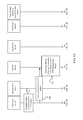
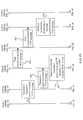
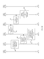
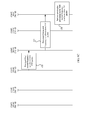
- FIG. 4A , FIG. 4B , and FIG. 4C are a schematic flowchart of a method according to a fourth embodiment of the present invention.
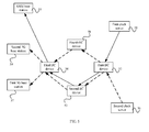
- FIG. 5 is a schematic structural diagram of a system corresponding to the fourth embodiment of the present invention.
- a Global System for Mobile Communication uses a layer 3 unicast mode to implement frequency synchronization.
- a path is: a first clock server (IPclk Server 1) 51 -> a first BC device 52 -> a second BC device 53 -> a third BC device 54 -> a GSM base station 55.
- IPclk Server 1 A Time Division Synchronous Code Division Multiple Access (Time Division Synchronous Code Division Multiple Access, TD-SCDMA) system uses a layer 2 or layer 3 multicast mode to implement time synchronization.
- a path is: a second clock server (IPclk Server 2) 56 -> the first BC device 52, and afterward, the path is divided into two paths from the first BC device 52.
- One path is: the first BC device 52 -> the second BC device 53 -> the third BC device 54 -> a first 3G base station (NodeB) 57, and the other path is: the first BC device 52 -> a fourth BC device 58 -> the third BC device 54 -> a second 3G base station 59.
- the clock server 51 and the GSM base station 55 are configured to have a same domain number, for example, DN 1; the second clock server 56, the first BC device 52, the second BC device 53, the third BC device 54, the fourth BC device 58, the first 3G base station 57, and the second 3G base station 59 are configured to have another same domain number, for example, DN 2.
- the first BC device 52, the second BC device 53, the third BC device 54, and the fourth BC device 58 are configured to be in a multicast mode.
- a destination address of a transmitted packet is an address compliant with a multicast protocol, that is, a class D IP address, ranging from 224.0.0.0 to 239.255.255.255; during unicast, the destination address of the transmitted packet is an IP address of the GSM base station.
- the BC device involved in this embodiment may be a network element such as a router and a switch.
- this embodiment includes:
- FIG. 4A , FIG. 4B , and FIG. 4C do not show the third BC device and the fourth BC device. However, it is understandable that deployment and functionality of these devices are still able to be determined from the text part and therefore still fall within a coverage scope of this embodiment of the present invention.
- Step 406 The GSM base station serves as an OC device, and after receiving the time-synchronization PTP packet, determines, according to the domain number and destination address carried in the time-synchronization PTP packet, that the time-synchronization PTP packet is a PTP packet of the device, and therefore performs terminating processing.
- the time-synchronization PTP packet is a PTP packet of the GMS base station.
- Step 407 The second clock server generates a frequency-synchronization PTP packet, where the frequency-synchronization PTP packet carries a domain number (DN 2) and a destination address (a multicast address) of the second clock server.
- DN 2 domain number
- a destination address a multicast address
- Step 408 The second clock server sends the frequency-synchronization PTP packet to the first BC device.
- Step 409 The first BC device determines, according to the domain number and destination address carried in the frequency-synchronization PTP packet, that the frequency-synchronization PTP packet is a PTP packet of the device.
- the destination address carried in the frequency-synchronization PTP packet is a multicast address of the first BC device itself, and the first BC device is configured to be in the multicast mode, the frequency-synchronization PTP packet is a PTP packet of the first BC device.
- Step 410 The first BC device terminates the frequency-synchronization PTP packet.
- Step 411 The first BC device uses its own time information to regenerate a frequency-synchronization PTP packet, where the regenerated frequency-synchronization PTP packet carries a domain number DN 2 and a multicast address serving as a destination address, and then sends the regenerated frequency-synchronization PTP packet to the second BC device and the fourth BC device respectively.
- Step 412 The second BC device and the third BC device, and the fourth BC device and the third BC device also perform the processing that is performed by the first BC device in the same way until the frequency-synchronization PTP packet (the regenerated frequency-synchronization PTP packet) is sent to the first 3G base station and the second 3G base station.
- Step 413 The first 3G base station and the second 3G base station are OC devices, and after receiving the frequency-synchronization PTP packet, determine, according to the domain number and destination address carried in the frequency-synchronization PTP packet, that the frequency-synchronization PTP packet is a PTP packet of the device, and therefore perform the terminating processing.
- the destination addresses carried in the frequency-synchronization PTP packet are multicast addresses of the first 3G base station and the second 3G base station respectively, and the first 3G base station and the second 3G base station are configured to be in the multicast mode, the frequency-synchronization PTP packet is a PTP packet of the first 3G base station and the second 3G base station.
- whether the PTP packet is not a PTP packet of the device is determined according to the domain number and the destination address; in a time synchronization system, end-to-end frequency synchronization may be further implemented smoothly when an intermediate node is a BC device.
- FIG. 6A , FIG. 6B , and FIG. 6C are a schematic flowchart of a method according to a fifth embodiment of the present invention.
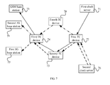
- FIG. 7 is a schematic structural diagram of a system corresponding to the fifth embodiment of the present invention.
- a GSM system uses a layer 3 unicast mode to implement frequency synchronization.
- a path is: a first clock server (IPclk Server 1) 71 -> a first TC device 72 -> a second TC device 73 -> a third TC device 74 -> a GSM base station 75.
- IPclk Server 1 IPclk Server 1
- a TD-SCDMA system uses a layer 2 or layer 3 unicast mode to implement time synchronization.
- Paths are: a second clock server (IPclk Server 2) 76 -> the first TC device 72 -> the second TC device 73 -> the third TC device 74 -> a first 3G base station (NodeB) 77, and the second clock server 76 -> the first TC device 72 -> the fourth TC device 78 -> the third TC device 74 -> a second 3G base station 79.
- IPclk Server 2 IPclk Server 2
- the first clock server 71 and the GSM base station 75 are configured to have a same domain number, for example, DN 1; the second clock server 76, the first TC device 72, the second TC device 73, the third TC device 74, the fourth TC device 78, the first 3G base station 77, and the second 3G base station 79 are configured to have another same domain number, for example, DN 2.
- the first TC device 72, the second TC device 73, the third TC device 74, the fourth TC device 78, the GSM base station 75, the first 3G base station, and the second 3G base station are configured to be in a unicast mode.
- destination addresses of the transmitted packet are an IP address of the GSM base station, an IP address of the first 3G base station, and an IP address of the second 3G base station respectively.
- the TC device involved in this embodiment may be a network element such as a router and a switch.
- this embodiment includes:
- the TC device may directly perform transparent transmission, or may perform relevant information processing and then perform transmission.
- Step 606 The GSM base station serves as an OC device, and after receiving the time-synchronization PTP packet, determines, according to the domain number and destination address carried in the time-synchronization PTP packet, that the time-synchronization PTP packet is a PTP packet of the device, and therefore performs terminating processing.
- the time-synchronization PTP packet is a PTP packet of the GMS base station.
- Step 607 The second clock server generates a first frequency-synchronization PTP packet and a second frequency-synchronization PTP packet, where the first frequency-synchronization PTP packet and the second frequency-synchronization PTP packet respectively carry a domain number and a destination address, both the domain number carried in the first frequency-synchronization PTP packet and that carried in the second frequency-synchronization PTP packet are the domain number (DN 2) of the second clock server, and the destination addresses are the IP address of the first 3G base station and the IP address of the second 3G base station respectively.
- DN 2 domain number of the second clock server
- Step 608 The second clock server sends both the first frequency-synchronization PTP packet and the second frequency-synchronization PTP packet to the first TC device.
- Step 609 The first TC device determines, according to the domain numbers carried in the first frequency-synchronization PTP packet and the second frequency-synchronization PTP packet, that the first frequency-synchronization PTP packet and the second frequency-synchronization PTP packet are PTP packets of the device.
- the first frequency-synchronization PTP packet and the second frequency-synchronization PTP packet are PTP packets of the first TC device.
- Step 610 After performing normal PTP layer processing on the first frequency-synchronization PTP packet and the second frequency-synchronization PTP packet, the first TC device respectively sends the processed first frequency-synchronization PTP packet and second frequency-synchronization PTP packet to the second TC device and the fourth TC device.
- Step 611 The second TC device and the third TC device, and the fourth TC device and the third TC device also perform the processing that is performed by the first TC device in the same way until the first frequency-synchronization PTP packet and the second frequency-synchronization PTP packet are respectively sent to the first 3G base station and the second 3G base station.
- FIG. 6A , FIG. 6B , and FIG. 6C do not show the third TC device and the fourth TC device. However, it is understandable that deployment and functionality of these devices are still able to be determined from the text part, and therefore still fall within a coverage scope of this embodiment of the present invention.
- Step 612 The first 3G base station and the second 3G base station are OC devices, and after respectively receiving the first frequency-synchronization PTP packet and the second frequency-synchronization PTP packet, determine, according to the domain number and destination address carried in the first frequency-synchronization PTP packet or the second frequency-synchronization PTP packet, that the first frequency-synchronization PTP packet or the second frequency-synchronization PTP packet is a PTP packet of the devices, and therefore perform the terminating processing.
- the domain numbers carried in the first frequency-synchronization PTP packet and the second frequency-synchronization PTP packet are DN 2, which is the same as the domain number DN 2 configured in the first 3G base station and the second 3G base station
- the destination addresses carried in the first frequency-synchronization PTP packet and the second frequency-synchronization PTP packet are the IP address of the first 3G base station and the IP address of the second 3G base station respectively, and the first 3G base station and the second 3G base station are configured to be in the unicast mode
- the first frequency-synchronization PTP packet and second frequency-synchronization PTP packet are a PTP packet of the first 3G base station and a PTP packet of the second 3G base station respectively.
- the OC device determines, according to the domain number and the destination address, whether the PTP packet is not a PTP packet of the device; the TC device determines, according to the domain number, whether the PTP packet is not a PTP packet of the device.
- end-to-end frequency synchronization may be further implemented smoothly when an intermediate node is a BC device.
- the fourth embodiment and the fifth embodiment respectively take the BC device and the TC device that serve as intermediate nodes as examples, and the end-to-end frequency synchronization is further implemented in a system which is already configured with time synchronization. It is understandable that the principle of the embodiments of the present invention may still be used to further implement the end-to-end time synchronization in a system which is already configured with frequency synchronization.
- a module performing the preceding processing on the clock device may specifically be a packet processing apparatus.
- a packet processing apparatus also exists in the clock device, but the packet processing apparatus in the prior art only processes the PTP packet of the device and cannot determine and process the PTP packet that is not a PTP packet of the device.
- the packet processing apparatus is improved to determine and process the PTP packet that is not a PTP packet of the device, and thereby smooth proceeding of end-to-end synchronization is ensured.
- an embodiment of the present invention may further provide a method for processing a PTP packet.
- This method is adding or extending an existing address matching apparatus in the clock device, so that the address matching apparatus provided in this embodiment of the present invention may be used for determining and processing a PTP packet that is not a PTP packet of the device.
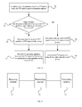
- FIG. 8 is a schematic flowchart of a method according to a sixth embodiment of the present invention, including:
- the node device other than the clock device is a next-hop node of the clock device determined based on information such as route information.
- the clock device may be a BC device, an OC device, or a TC device.
- whether a PTP packet is not a PTP packet of the device is determined by using an address matching manner, which may also implement determining and processing of the PTP packet that is not a PTP packet of the device and ensure implementation of end-to-end synchronization.
- domain numbers do not need to be compared and therefore execution is simple and convenient.
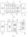
- FIG. 9 is a schematic structural diagram of a clock device according to a seventh embodiment of the present invention.
- the clock device includes a receiving module 91, a determining module 92, and a forwarding module 93.
- the receiving module 91 is configured to receive a Precision Time Protocol PTP packet, where the Precision Time Protocol packet carries end-to-end parameter information.
- the determining module 92 is configured to determine, according to the end-to-end parameter information, whether the received Precision Time Protocol packet is not a Precision Time Protocol packet of the device.
- the forwarding module 93 is configured to forward the Precision Time Protocol packet that is not a Precision Time Protocol packet of the device when the received Precision Time Protocol packet is not a Precision Time Protocol packet of the device.
- the PTP packet that is not a PTP packet of the device is determined according to the end-to-end parameter information and forwarding processing is performed on the PTP packet that is not a PTP packet of the device, which implements determining and processing of the PTP packet that is not a PTP packet of the device. This may avoid a problem of discarding a PTP packet that is not a PTP packet of the device and ensure implementation of end-to-end synchronization.
- respective deployment may be performed based on different clock devices.
- FIG. 10 is a schematic structural diagram of a clock device according to an eighth embodiment of the present invention.
- the clock device may be a BC device or an OC device, and in this case, the end-to-end parameter information includes a domain number and a destination address.
- the determining module 92 includes a first judging unit 101 and a first determining unit 102, where the first judging unit 101 is configured to judge whether the domain number is the same as a domain number configured in the clock device itself, and the first determining unit 102 is configured to determine that a received PTP packet is not a PTP packet of the device when a judgment result obtained by the first judging unit 101 is that the domain number is different from the domain number configured in the clock device itself; or, the determining module 92 includes the first judging unit 101, a second judging unit 103, and a second determining unit 104, where the second judging unit 103 is configured to further judge whether the destination address is a multicast address of the clock device itself when the judgment result obtained by the first judging unit 101 is that the domain number is the same as the domain number configured in the clock device itself and the clock device is in a multicast mode, and the second determining unit 104 is configured to determine that the received PTP packet is not a PTP packet of the device when a judgment
- the forwarding module 93 includes a first forwarding unit 107, where the first forwarding unit 107 is configured to ignore PTP layer processing on the PTP packet that is not a PTP packet of the device and directly forward the PTP packet that is not a PTP packet of the device to a node device other than the clock device.
- the PTP packet that is not a PTP packet of the device is determined according to the domain number and the destination address, so that the BC device or the OC device processes the received PTP packet, thereby ensuring implementation of end-to-end synchronization.
- FIG. 11 is a schematic structural diagram of a clock device according to a ninth embodiment of the present invention.
- the clock device is a TC device, and in this case, the end-to-end parameter information includes a domain number.
- the determining module 92 includes a fourth judging unit 111, a fourth determining unit 112, and a fifth determining unit 113.
- the fourth judging unit 111 is configured to judge whether the domain number is the same as a domain number configured in the TC device itself.
- the fourth determining unit 112 is configured to determine that a received PTP packet is not a PTP packet of the device when a judgment result obtained by the fourth judging unit 111 is that the domain number is different from the domain number configured in the TC device itself.
- the fifth determining unit 113 is configured to determine that the received PTP packet is a PTP packet of the device when the judgment result obtained by the fourth judging unit 111 is that the domain number is the same as the domain number configured in the TC device itself.
- the forwarding module 93 includes a second forwarding unit 114 or a third forwarding unit 115.
- the second forwarding unit 114 is configured to ignore PTP layer processing on the PTP packet that is not a PTP packet of the device and directly forward the PTP packet that is not a PTP packet of the device to a node device other than the TC device.
- the third forwarding unit 115 is configured to perform normal PTP layer processing on the PTP packet that is not a PTP packet of the device and forward the processed PTP packet that is not a PTP packet of the device to a node device other than the TC device.
- the PTP packet that is not a PTP packet of the device is determined according to the domain number, so that the TC device processes the received PTP packet, thereby ensuring implementation of end-to-end synchronization.
- Each module involved in the embodiment of FIG. 10 or FIG. 11 may be specifically located in the packet processing apparatus of the clock device.
- FIG. 12 is a schematic structural diagram of a clock device according to a tenth embodiment of the present invention.
- the clock device is a BC device, an OC device or a TC device, and in this case, the end-to-end parameter information includes a destination address.
- the determining module 92 includes a fifth judging unit 121 and a sixth determining unit 122.
- the fifth judging unit 121 is configured to judge whether the destination address is a port address of the clock device itself.
- the sixth determining unit 122 is configured to, determine that a PTP packet received by the clock device is not a PTP packet of the device when a judgment result obtained by the fifth judging unit 121 is that the destination address is not the port address of the clock device itself.
- the modules (including the receiving module 91, the determining module 92, and the forwarding module 93) involved in this embodiment may be specifically located in an address matching apparatus 1 of the clock device.
- the clock device further includes a packet processing apparatus 2, and the address matching apparatus 1 may further include: a seventh determining unit 123, configured to determine that the received PTP packet is a PTP packet of the device when the judgment result obtained by the fifth judging unit 121 is that the destination address is the port address of the clock device itself, and forward the PTP packet of the device to the packet processing apparatus 2 in the clock device, so that the packet processing apparatus 2 performs normal PTP layer processing on the PTP packet of the device.
- whether a PTP packet is not a PTP packet of the device is determined by using an address matching manner, which may also implement determining and processing of the PTP packet that is not a PTP packet of the device and ensure implementation of end-to-end synchronization.
- domain numbers do not need to be compared and therefore execution is simple and convenient.
- An embodiment of the present invention further provides another implementation solution (which may be called “a profile implementation solution”).
- a clock device may be an ordinary clock OC device or a boundary clock BC device or a transparent clock TC device
- a PTP packet is a PTP message sent by a master clock or a slave clock
- end-to-end parameter information includes profile information in the PTP message.
- the clock device may determine, according to the end-to-end parameter information, whether a received PTP packet is not a PTP packet of the device.
- the profile information may be a type-length-value TLV field including a profile ID; accordingly, the clock device may judge, according to the profile information in the PTP message, whether the PTP message is relevant to (or is not a PTP packet of the device) the device. For example, if the profile ID included in the TLV field matches a profile ID configured in the clock device, it is determined that the PTP message is relevant to the device; if the profile ID included in the TLV field does not match a profile ID configured in the clock device, it is determined that the PTP message is irrelevant to the device.
- the step of forwarding the PTP packet that is not a PTP packet of the device may include the following: The TC device ignores PTP layer processing on the PTP packet that is not a PTP packet of the device and directly forwards the PTP packet that is not a PTP packet of the device to a node device other than the TC device; or the TC device performs normal PTP layer processing on the PTP packet that is not a PTP packet of the device and forwards the processed PTP packet that is not a PTP packet of the device to a node device other than the TC device.
- a TLV field is added to a 1588 packet:
- the GSM system uses the layer 3 unicast mode to implement the frequency synchronization.
- the path is: the first clock server 51 -> the first BC device 52 -> the second BC device 53 -> the third BC device 54 -> the GSM base station 55.
- the TD-SCDMA system uses the layer 2 or layer 3 multicast mode to implement the time synchronization.
- the path is: the second clock server 56 -> the first BC device 52, and afterward, the path is divided into two paths from the first BC device 52.
- One path is: the first BC device 52 -> the second BC device 53 -> the third BC device 54 -> the first 3G base station (NodeB) 57, and the other path is: the first BC device 52 -> the fourth BC device 58 -> the third BC device 54 -> the second 3G base station 59.
- a principle of performing terminating processing on a PTP packet by the OC device is similar to a principle of performing terminating processing on a PTP packet by the BC device.
- This embodiment of the present invention mainly takes the BC device as an example for description but is not limited thereto.
- the first clock server 51 and the GSM base station 55 are configured to have the same domain number, for example, DN 1; the second clock server 56, the first BC device 52, the second BC device 53, the third BC device 54, the fourth BC device 58, the first 3G base station 57, and the second 3G base station 59 are configured to have another same domain number, for example, DN 2.
- the first BC device 52, the second BC device 53, the third BC device 54, and the fourth BC device 58 are configured to be in the multicast mode.
- the destination address of the transmitted packet is an address compliant with the multicast protocol, that is, a class D IP address, ranging from 224.0.0.0 to 239.255.255.255; during unicast, the destination address of the transmitted packet is the IP address of the GSM base station.
- the first clock server 51 and the GSM base station involved in unicast and a network element (such as a BC device) involved in multicast belong to different telecom profiles, different profile IDs may be configured.
- a TLV field including a profile ID may be added to a 1588 packet sent by the first clock server 51, and an intermediate BC device may judge whether the profile ID in the packet matches a profile ID of the BC device.
- the intermediate BC node terminates only the multicast packet and transparently transmits a unicast packet after comparing the profile IDs.
- the GSM system uses the layer 3 unicast mode to implement the frequency synchronization.
- the path is: the first clock server 71 -> the first TC device 72 -> the second TC device 73 -> the third TC device 74 -> the GSM base station 75.
- the TD-SCDMA system uses the layer 2 or layer 3 unicast mode to implement the time synchronization.
- the path is: the second clock server (IPclk Server 2) 76 -> the first TC device 72 -> the second TC device 73 -> the third TC device 74 -> the first 3G base station (NodeB) 77, and the second clock server 76 -> the first TC device 72 -> the fourth TC device 78 -> the third TC device 74 -> the second 3G base station 79.
- IPclk Server 2 IPclk Server 2
- the first clock server 71 and the GSM base station 75 are configured to have the same domain number, for example, DN 1; the second clock server 76, the first TC device 72, the second TC device 73, the third TC device 74, the fourth TC device 78, the first 3G base station 77, and the second 3G base station 79 are configured to have another same domain number, for example, DN 2.
- the first TC device 72, the second TC device 73, the third TC device 74, the fourth TC device 78, the GSM base station 75, the first 3G base station, and the second 3G base station are configured to be in the unicast mode.
- the destination addresses of the transmitted packet are the IP address of the GSM base station, the IP address of the first 3G base station, and the IP address of the second 3G base station respectively.
- the first clock server 71 and the GSM base station involved in unicast and a network element (such as a TC device) involved in multicast belong to different telecom profiles, different profile IDs may be configured.
- a TLV field including a profile ID may be added to a 1588 packet sent by the first clock server 71, and an intermediate TC node may judge whether the profile ID in the packet matches a profile ID of the TC device.
- the intermediate TC node processes dwell time of the multicast packet and directly and transparently transmits a unicast packet after comparing profile IDs.
- the dwell time of the packet may also be processed according to a protocol.
- a profile judging unit and a profile determining unit may be configured in the determining module to implement the "profile implementation solution”.
- the determining module includes the profile judging unit and the profile determining unit.
- the profile judging unit is configured to judge, according to the profile information in the PTP message, whether the PTP message is relevant to the device.
- the profile determining unit is configured to determine that the received PTP packet is not a PTP packet of the device when a judgment result obtained by the profile judging unit is that the PTP message is irrelevant to the device.
- the forwarding module may include a second forwarding unit or a third forwarding unit, where the second forwarding unit is configured to ignore PTP layer processing on the PTP packet that is not a PTP packet of the device and directly forward the PTP packet that is not a PTP packet of the device to a node device other than the TC device, and the third forwarding unit is configured to perform normal PTP layer processing on the PTP packet that is not a PTP packet of the device and forward the processed PTP packet that is not a PTP packet of the device to a node device other than the TC device.
- the preceding embodiments may be applied in different systems, for example, a GSM system, a WCDMA system, or a Long Term Evolution (Long Term Evolution, LTE) system, or applied in a hybrid network system of the preceding systems.
- GSM Global System for Mobile communications
- WCDMA Wideband Code Division Multiple Access
- LTE Long Term Evolution
Landscapes
- Engineering & Computer Science (AREA)
- Computer Networks & Wireless Communication (AREA)
- Signal Processing (AREA)
- Data Exchanges In Wide-Area Networks (AREA)
- Mobile Radio Communication Systems (AREA)
- Synchronisation In Digital Transmission Systems (AREA)
Applications Claiming Priority (3)
| Application Number | Priority Date | Filing Date | Title |
|---|---|---|---|
| CN200910093302 | 2009-09-17 | ||
| CN201010107643.8A CN102026364B (zh) | 2009-09-17 | 2010-01-25 | 精确时间协议报文处理方法和时钟设备 |
| PCT/CN2010/076939 WO2011032494A1 (fr) | 2009-09-17 | 2010-09-15 | Procédé et dispositif d'horloge pour traiter un message de protocole de synchronisation d'horloge |
Publications (3)
| Publication Number | Publication Date |
|---|---|
| EP2472916A1 true EP2472916A1 (fr) | 2012-07-04 |
| EP2472916A4 EP2472916A4 (fr) | 2012-11-14 |
| EP2472916B1 EP2472916B1 (fr) | 2016-02-17 |
Family
ID=43758111
Family Applications (1)
| Application Number | Title | Priority Date | Filing Date |
|---|---|---|---|
| EP10816698.4A Active EP2472916B1 (fr) | 2009-09-17 | 2010-09-15 | Procédé et dispositif d'horloge pour traiter un message de protocole de synchronisation d'horloge |
Country Status (4)
| Country | Link |
|---|---|
| EP (1) | EP2472916B1 (fr) |
| JP (1) | JP5455138B2 (fr) |
| CN (1) | CN102026364B (fr) |
| WO (1) | WO2011032494A1 (fr) |
Cited By (3)
| Publication number | Priority date | Publication date | Assignee | Title |
|---|---|---|---|---|
| CN105103632A (zh) * | 2014-01-28 | 2015-11-25 | 华为技术有限公司 | 同步信号转发方法和用户设备 |
| EP2976922A4 (fr) * | 2013-03-19 | 2016-03-16 | Ericsson Telefon Ab L M | Fourniture d'une synchronisation de paquets dans un réseau privé virtuel |
| WO2020172085A1 (fr) * | 2019-02-18 | 2020-08-27 | Qualcomm Incorporated | Améliorations de communication sans fil pour horloges transparentes et de limite |
Families Citing this family (8)
| Publication number | Priority date | Publication date | Assignee | Title |
|---|---|---|---|---|
| EP2487819B1 (fr) * | 2011-02-10 | 2015-08-05 | Alcatel Lucent | Élément de réseau pour réseau de commutation de paquets |
| CN102185686B (zh) * | 2011-05-16 | 2016-09-21 | 南京中兴软件有限责任公司 | 基于ieee 1588协议调整频率的方法及网络装置 |
| WO2013143112A1 (fr) * | 2012-03-30 | 2013-10-03 | Telefonaktiebolaget L M Ericsson(Publ) | Procédé et système de synchronisation de protocole temporel robuste de précision |
| CN103428081A (zh) * | 2012-05-14 | 2013-12-04 | 中兴通讯股份有限公司 | 一种分组网络同步方法、装置及系统 |
| CN103428086B (zh) * | 2012-05-25 | 2016-08-03 | 北京东土科技股份有限公司 | 基于ptp协议的透明时钟被动端口选举方法及装置 |
| CN103078699B (zh) * | 2012-12-28 | 2015-08-05 | 华为技术有限公司 | 基于精密时间协议进行时间同步的方法和网络设备 |
| CN103532970B (zh) * | 2013-10-23 | 2016-12-07 | 杭州华三通信技术有限公司 | 一种时间同步报文的传输方法和设备 |
| EP4173179B1 (fr) * | 2020-08-05 | 2025-07-09 | Nokia Technologies Oy | Détermination de l'horloge de travail pour un équipement utilisateur mobile |
Family Cites Families (8)
| Publication number | Priority date | Publication date | Assignee | Title |
|---|---|---|---|---|
| US5469432A (en) * | 1993-08-26 | 1995-11-21 | Gat; Erann | High-speed digital communications network |
| US6982976B2 (en) * | 2000-08-11 | 2006-01-03 | Texas Instruments Incorporated | Datapipe routing bridge |
| JP2003143178A (ja) * | 2001-10-31 | 2003-05-16 | Fujitsu Ltd | デジタル伝送装置 |
| US7633870B2 (en) * | 2005-04-18 | 2009-12-15 | Symmetricom, Inc. | Network forwarding device and method that forward timing packets through the device with a constant delay |
| US7689854B2 (en) * | 2006-09-22 | 2010-03-30 | Agilent Technologies, Inc. | Method and apparatus for establishing IEEE 1588 clock synchronization across a network element comprising first and second cooperating smart interface converters wrapping the network element |
| US8730867B2 (en) * | 2007-02-05 | 2014-05-20 | Thomson Licensing | Clock synchronization aid device for communication station(s) of a wireless network, and associated clock synchronization device |
| JP2009065579A (ja) * | 2007-09-10 | 2009-03-26 | Nec Corp | 時刻同期システム、時刻同期方法、ノード及びプログラム |
| CN101217498B (zh) * | 2008-01-18 | 2011-08-24 | 北京科技大学 | 基于数据报文点点决策的自组织网络寻路方法 |
-
2010
- 2010-01-25 CN CN201010107643.8A patent/CN102026364B/zh not_active Expired - Fee Related
- 2010-09-15 WO PCT/CN2010/076939 patent/WO2011032494A1/fr not_active Ceased
- 2010-09-15 JP JP2012529112A patent/JP5455138B2/ja active Active
- 2010-09-15 EP EP10816698.4A patent/EP2472916B1/fr active Active
Cited By (8)
| Publication number | Priority date | Publication date | Assignee | Title |
|---|---|---|---|---|
| EP2976922A4 (fr) * | 2013-03-19 | 2016-03-16 | Ericsson Telefon Ab L M | Fourniture d'une synchronisation de paquets dans un réseau privé virtuel |
| CN105103632A (zh) * | 2014-01-28 | 2015-11-25 | 华为技术有限公司 | 同步信号转发方法和用户设备 |
| CN105103632B (zh) * | 2014-01-28 | 2019-02-12 | 华为技术有限公司 | 同步信号转发方法和用户设备 |
| WO2020172085A1 (fr) * | 2019-02-18 | 2020-08-27 | Qualcomm Incorporated | Améliorations de communication sans fil pour horloges transparentes et de limite |
| US11228994B2 (en) | 2019-02-18 | 2022-01-18 | Qualcomm Incorporated | Wireless communication enhancements for transparent and boundary clocks |
| US11653317B2 (en) | 2019-02-18 | 2023-05-16 | Qualcomm Incorporated | Wireless communication enhancements for transparent and boundary clocks |
| US11937196B2 (en) | 2019-02-18 | 2024-03-19 | Qualcomm Incorporated | Wireless communication enhancements for transparent and boundary |
| US12192931B2 (en) | 2019-02-18 | 2025-01-07 | Qualcomm Incorporated | Wireless communication enhancements for transparent and boundary clocks |
Also Published As
| Publication number | Publication date |
|---|---|
| JP5455138B2 (ja) | 2014-03-26 |
| CN102026364B (zh) | 2014-07-09 |
| WO2011032494A1 (fr) | 2011-03-24 |
| EP2472916A4 (fr) | 2012-11-14 |
| JP2013509744A (ja) | 2013-03-14 |
| EP2472916B1 (fr) | 2016-02-17 |
| CN102026364A (zh) | 2011-04-20 |
Similar Documents
| Publication | Publication Date | Title |
|---|---|---|
| EP2472916B1 (fr) | Procédé et dispositif d'horloge pour traiter un message de protocole de synchronisation d'horloge | |
| US20220311533A1 (en) | 5g system support for conveying tsn time synchronization | |
| US10827546B2 (en) | Time synchronization for multi-link D2D and cellular communication | |
| US20230092723A1 (en) | Communication Method, Apparatus, and Computer-Readable Storage Medium | |
| EP3761533B1 (fr) | Émission d'informations de temps de séjour dans un réseau | |
| EP3614586B1 (fr) | Procédé, noeud et système de détection de chemin de synchronisation d'horloge | |
| CN116250299B (zh) | 一种应对链路异常的授时方法和装置 | |
| US12143899B2 (en) | Message transmission method and apparatus | |
| CN102006660B (zh) | 一种时间同步的方法和系统 | |
| CN101616163A (zh) | 精确时间传递协议报文处理方法及装置 | |
| EP3104556A1 (fr) | Procédé et dispositif de synchronisation d'horloge, et système de communication | |
| Manolakis et al. | Time synchronization for multi-link D2D/V2X communication | |
| WO2010050302A1 (fr) | Système de communication mobile, station de commande, station de base, procédé de communication et programme | |
| CN106411445A (zh) | 一种通信系统中同步信号的发送方法、同步方法及装置 | |
| JP2012520591A (ja) | 少なくとも1つのタイミング配信プロトコルにより第1のデータおよび第2のデータを別々に伝送することによってクロックを同期するための方法、ならびに関連するシステムおよびモジュール | |
| CN114245388A (zh) | 融合5g接入和自组织网接入的一体化系统和方法 | |
| CN102412956B (zh) | 协议单播方式同步的方法、设备和系统 | |
| JP5302051B2 (ja) | 無線基地局、無線制御装置及び無線装置 | |
| US20250286776A1 (en) | Detnet yang model mapping to 3gpp configuration | |
| US20230164713A1 (en) | Information control method and apparatus, and communications device | |
| CN114915988B (zh) | 信息传输方法、通信设备及存储介质 | |
| US8705499B2 (en) | Mobile wireless access router for separately controlling traffic signal and control signal | |
| WO2016138747A1 (fr) | Procédé et appareil de synchronisation d'informations | |
| EP2707976B1 (fr) | Synchronisation temporelle dans un réseau de communication | |
| Chowdhury | Synchronization for Telecom Infrastructure |
Legal Events
| Date | Code | Title | Description |
|---|---|---|---|
| PUAI | Public reference made under article 153(3) epc to a published international application that has entered the european phase |
Free format text: ORIGINAL CODE: 0009012 |
|
| 17P | Request for examination filed |
Effective date: 20120327 |
|
| AK | Designated contracting states |
Kind code of ref document: A1 Designated state(s): AL AT BE BG CH CY CZ DE DK EE ES FI FR GB GR HR HU IE IS IT LI LT LU LV MC MK MT NL NO PL PT RO SE SI SK SM TR |
|
| A4 | Supplementary search report drawn up and despatched |
Effective date: 20121016 |
|
| RIC1 | Information provided on ipc code assigned before grant |
Ipc: H04W 4/18 20090101AFI20121010BHEP Ipc: H04J 3/06 20060101ALI20121010BHEP Ipc: H04J 3/14 20060101ALI20121010BHEP |
|
| DAX | Request for extension of the european patent (deleted) | ||
| GRAP | Despatch of communication of intention to grant a patent |
Free format text: ORIGINAL CODE: EPIDOSNIGR1 |
|
| INTG | Intention to grant announced |
Effective date: 20150729 |
|
| GRAS | Grant fee paid |
Free format text: ORIGINAL CODE: EPIDOSNIGR3 |
|
| GRAA | (expected) grant |
Free format text: ORIGINAL CODE: 0009210 |
|
| AK | Designated contracting states |
Kind code of ref document: B1 Designated state(s): AL AT BE BG CH CY CZ DE DK EE ES FI FR GB GR HR HU IE IS IT LI LT LU LV MC MK MT NL NO PL PT RO SE SI SK SM TR |
|
| REG | Reference to a national code |
Ref country code: GB Ref legal event code: FG4D |
|
| REG | Reference to a national code |
Ref country code: CH Ref legal event code: EP |
|
| REG | Reference to a national code |
Ref country code: IE Ref legal event code: FG4D |
|
| REG | Reference to a national code |
Ref country code: AT Ref legal event code: REF Ref document number: 776116 Country of ref document: AT Kind code of ref document: T Effective date: 20160315 |
|
| REG | Reference to a national code |
Ref country code: DE Ref legal event code: R096 Ref document number: 602010030763 Country of ref document: DE |
|
| REG | Reference to a national code |
Ref country code: NL Ref legal event code: MP Effective date: 20160217 |
|
| REG | Reference to a national code |
Ref country code: LT Ref legal event code: MG4D |
|
| REG | Reference to a national code |
Ref country code: AT Ref legal event code: MK05 Ref document number: 776116 Country of ref document: AT Kind code of ref document: T Effective date: 20160217 |
|
| PG25 | Lapsed in a contracting state [announced via postgrant information from national office to epo] |
Ref country code: IT Free format text: LAPSE BECAUSE OF FAILURE TO SUBMIT A TRANSLATION OF THE DESCRIPTION OR TO PAY THE FEE WITHIN THE PRESCRIBED TIME-LIMIT Effective date: 20160217 Ref country code: ES Free format text: LAPSE BECAUSE OF FAILURE TO SUBMIT A TRANSLATION OF THE DESCRIPTION OR TO PAY THE FEE WITHIN THE PRESCRIBED TIME-LIMIT Effective date: 20160217 Ref country code: GR Free format text: LAPSE BECAUSE OF FAILURE TO SUBMIT A TRANSLATION OF THE DESCRIPTION OR TO PAY THE FEE WITHIN THE PRESCRIBED TIME-LIMIT Effective date: 20160518 Ref country code: NO Free format text: LAPSE BECAUSE OF FAILURE TO SUBMIT A TRANSLATION OF THE DESCRIPTION OR TO PAY THE FEE WITHIN THE PRESCRIBED TIME-LIMIT Effective date: 20160517 Ref country code: FI Free format text: LAPSE BECAUSE OF FAILURE TO SUBMIT A TRANSLATION OF THE DESCRIPTION OR TO PAY THE FEE WITHIN THE PRESCRIBED TIME-LIMIT Effective date: 20160217 |
|
| REG | Reference to a national code |
Ref country code: FR Ref legal event code: PLFP Year of fee payment: 7 |
|
| PG25 | Lapsed in a contracting state [announced via postgrant information from national office to epo] |
Ref country code: PL Free format text: LAPSE BECAUSE OF FAILURE TO SUBMIT A TRANSLATION OF THE DESCRIPTION OR TO PAY THE FEE WITHIN THE PRESCRIBED TIME-LIMIT Effective date: 20160217 Ref country code: SE Free format text: LAPSE BECAUSE OF FAILURE TO SUBMIT A TRANSLATION OF THE DESCRIPTION OR TO PAY THE FEE WITHIN THE PRESCRIBED TIME-LIMIT Effective date: 20160217 Ref country code: PT Free format text: LAPSE BECAUSE OF FAILURE TO SUBMIT A TRANSLATION OF THE DESCRIPTION OR TO PAY THE FEE WITHIN THE PRESCRIBED TIME-LIMIT Effective date: 20160617 Ref country code: NL Free format text: LAPSE BECAUSE OF FAILURE TO SUBMIT A TRANSLATION OF THE DESCRIPTION OR TO PAY THE FEE WITHIN THE PRESCRIBED TIME-LIMIT Effective date: 20160217 Ref country code: LT Free format text: LAPSE BECAUSE OF FAILURE TO SUBMIT A TRANSLATION OF THE DESCRIPTION OR TO PAY THE FEE WITHIN THE PRESCRIBED TIME-LIMIT Effective date: 20160217 Ref country code: AT Free format text: LAPSE BECAUSE OF FAILURE TO SUBMIT A TRANSLATION OF THE DESCRIPTION OR TO PAY THE FEE WITHIN THE PRESCRIBED TIME-LIMIT Effective date: 20160217 Ref country code: LV Free format text: LAPSE BECAUSE OF FAILURE TO SUBMIT A TRANSLATION OF THE DESCRIPTION OR TO PAY THE FEE WITHIN THE PRESCRIBED TIME-LIMIT Effective date: 20160217 |
|
| PG25 | Lapsed in a contracting state [announced via postgrant information from national office to epo] |
Ref country code: EE Free format text: LAPSE BECAUSE OF FAILURE TO SUBMIT A TRANSLATION OF THE DESCRIPTION OR TO PAY THE FEE WITHIN THE PRESCRIBED TIME-LIMIT Effective date: 20160217 Ref country code: DK Free format text: LAPSE BECAUSE OF FAILURE TO SUBMIT A TRANSLATION OF THE DESCRIPTION OR TO PAY THE FEE WITHIN THE PRESCRIBED TIME-LIMIT Effective date: 20160217 |
|
| REG | Reference to a national code |
Ref country code: DE Ref legal event code: R097 Ref document number: 602010030763 Country of ref document: DE |
|
| PG25 | Lapsed in a contracting state [announced via postgrant information from national office to epo] |
Ref country code: CZ Free format text: LAPSE BECAUSE OF FAILURE TO SUBMIT A TRANSLATION OF THE DESCRIPTION OR TO PAY THE FEE WITHIN THE PRESCRIBED TIME-LIMIT Effective date: 20160217 Ref country code: RO Free format text: LAPSE BECAUSE OF FAILURE TO SUBMIT A TRANSLATION OF THE DESCRIPTION OR TO PAY THE FEE WITHIN THE PRESCRIBED TIME-LIMIT Effective date: 20160217 Ref country code: SM Free format text: LAPSE BECAUSE OF FAILURE TO SUBMIT A TRANSLATION OF THE DESCRIPTION OR TO PAY THE FEE WITHIN THE PRESCRIBED TIME-LIMIT Effective date: 20160217 Ref country code: SK Free format text: LAPSE BECAUSE OF FAILURE TO SUBMIT A TRANSLATION OF THE DESCRIPTION OR TO PAY THE FEE WITHIN THE PRESCRIBED TIME-LIMIT Effective date: 20160217 |
|
| PLBE | No opposition filed within time limit |
Free format text: ORIGINAL CODE: 0009261 |
|
| STAA | Information on the status of an ep patent application or granted ep patent |
Free format text: STATUS: NO OPPOSITION FILED WITHIN TIME LIMIT |
|
| PG25 | Lapsed in a contracting state [announced via postgrant information from national office to epo] |
Ref country code: BE Free format text: LAPSE BECAUSE OF FAILURE TO SUBMIT A TRANSLATION OF THE DESCRIPTION OR TO PAY THE FEE WITHIN THE PRESCRIBED TIME-LIMIT Effective date: 20160217 |
|
| RAP2 | Party data changed (patent owner data changed or rights of a patent transferred) |
Owner name: HUAWEI TECHNOLOGIES CO., LTD. |
|
| 26N | No opposition filed |
Effective date: 20161118 |
|
| PG25 | Lapsed in a contracting state [announced via postgrant information from national office to epo] |
Ref country code: SI Free format text: LAPSE BECAUSE OF FAILURE TO SUBMIT A TRANSLATION OF THE DESCRIPTION OR TO PAY THE FEE WITHIN THE PRESCRIBED TIME-LIMIT Effective date: 20160217 Ref country code: BG Free format text: LAPSE BECAUSE OF FAILURE TO SUBMIT A TRANSLATION OF THE DESCRIPTION OR TO PAY THE FEE WITHIN THE PRESCRIBED TIME-LIMIT Effective date: 20160517 |
|
| PG25 | Lapsed in a contracting state [announced via postgrant information from national office to epo] |
Ref country code: MC Free format text: LAPSE BECAUSE OF FAILURE TO SUBMIT A TRANSLATION OF THE DESCRIPTION OR TO PAY THE FEE WITHIN THE PRESCRIBED TIME-LIMIT Effective date: 20160217 |
|
| REG | Reference to a national code |
Ref country code: CH Ref legal event code: PL |
|
| REG | Reference to a national code |
Ref country code: IE Ref legal event code: MM4A |
|
| PG25 | Lapsed in a contracting state [announced via postgrant information from national office to epo] |
Ref country code: IE Free format text: LAPSE BECAUSE OF NON-PAYMENT OF DUE FEES Effective date: 20160915 Ref country code: CH Free format text: LAPSE BECAUSE OF NON-PAYMENT OF DUE FEES Effective date: 20160930 Ref country code: LI Free format text: LAPSE BECAUSE OF NON-PAYMENT OF DUE FEES Effective date: 20160930 |
|
| REG | Reference to a national code |
Ref country code: FR Ref legal event code: PLFP Year of fee payment: 8 |
|
| PG25 | Lapsed in a contracting state [announced via postgrant information from national office to epo] |
Ref country code: LU Free format text: LAPSE BECAUSE OF NON-PAYMENT OF DUE FEES Effective date: 20160915 |
|
| PG25 | Lapsed in a contracting state [announced via postgrant information from national office to epo] |
Ref country code: CY Free format text: LAPSE BECAUSE OF FAILURE TO SUBMIT A TRANSLATION OF THE DESCRIPTION OR TO PAY THE FEE WITHIN THE PRESCRIBED TIME-LIMIT Effective date: 20160217 Ref country code: HU Free format text: LAPSE BECAUSE OF FAILURE TO SUBMIT A TRANSLATION OF THE DESCRIPTION OR TO PAY THE FEE WITHIN THE PRESCRIBED TIME-LIMIT; INVALID AB INITIO Effective date: 20100915 |
|
| PG25 | Lapsed in a contracting state [announced via postgrant information from national office to epo] |
Ref country code: HR Free format text: LAPSE BECAUSE OF FAILURE TO SUBMIT A TRANSLATION OF THE DESCRIPTION OR TO PAY THE FEE WITHIN THE PRESCRIBED TIME-LIMIT Effective date: 20160217 Ref country code: TR Free format text: LAPSE BECAUSE OF FAILURE TO SUBMIT A TRANSLATION OF THE DESCRIPTION OR TO PAY THE FEE WITHIN THE PRESCRIBED TIME-LIMIT Effective date: 20160217 Ref country code: MT Free format text: LAPSE BECAUSE OF NON-PAYMENT OF DUE FEES Effective date: 20160930 Ref country code: MK Free format text: LAPSE BECAUSE OF FAILURE TO SUBMIT A TRANSLATION OF THE DESCRIPTION OR TO PAY THE FEE WITHIN THE PRESCRIBED TIME-LIMIT Effective date: 20160217 Ref country code: IS Free format text: LAPSE BECAUSE OF FAILURE TO SUBMIT A TRANSLATION OF THE DESCRIPTION OR TO PAY THE FEE WITHIN THE PRESCRIBED TIME-LIMIT Effective date: 20160217 |
|
| REG | Reference to a national code |
Ref country code: FR Ref legal event code: PLFP Year of fee payment: 9 |
|
| PG25 | Lapsed in a contracting state [announced via postgrant information from national office to epo] |
Ref country code: AL Free format text: LAPSE BECAUSE OF FAILURE TO SUBMIT A TRANSLATION OF THE DESCRIPTION OR TO PAY THE FEE WITHIN THE PRESCRIBED TIME-LIMIT Effective date: 20160217 |
|
| PGFP | Annual fee paid to national office [announced via postgrant information from national office to epo] |
Ref country code: DE Payment date: 20240730 Year of fee payment: 15 |
|
| PGFP | Annual fee paid to national office [announced via postgrant information from national office to epo] |
Ref country code: GB Payment date: 20240801 Year of fee payment: 15 |
|
| PGFP | Annual fee paid to national office [announced via postgrant information from national office to epo] |
Ref country code: FR Payment date: 20240808 Year of fee payment: 15 |