EP2472999A1 - Champ de cuisson et procédé de commande de l'apport énergétique sur un élément de chauffe d'un champ de cuisson - Google Patents
Champ de cuisson et procédé de commande de l'apport énergétique sur un élément de chauffe d'un champ de cuisson Download PDFInfo
- Publication number
- EP2472999A1 EP2472999A1 EP11194251A EP11194251A EP2472999A1 EP 2472999 A1 EP2472999 A1 EP 2472999A1 EP 11194251 A EP11194251 A EP 11194251A EP 11194251 A EP11194251 A EP 11194251A EP 2472999 A1 EP2472999 A1 EP 2472999A1
- Authority
- EP
- European Patent Office
- Prior art keywords
- heating element
- hob
- input interface
- control parameter
- parameter
- Prior art date
- Legal status (The legal status is an assumption and is not a legal conclusion. Google has not performed a legal analysis and makes no representation as to the accuracy of the status listed.)
- Granted
Links
Images

Classifications
-
- H—ELECTRICITY
- H05—ELECTRIC TECHNIQUES NOT OTHERWISE PROVIDED FOR
- H05B—ELECTRIC HEATING; ELECTRIC LIGHT SOURCES NOT OTHERWISE PROVIDED FOR; CIRCUIT ARRANGEMENTS FOR ELECTRIC LIGHT SOURCES, IN GENERAL
- H05B3/00—Ohmic-resistance heating
- H05B3/68—Heating arrangements specially adapted for cooking plates or analogous hot-plates
- H05B3/74—Non-metallic plates, e.g. vitroceramic, ceramic or glassceramic hobs, also including power or control circuits
- H05B3/746—Protection, e.g. overheat cutoff, hot plate indicator
-
- H—ELECTRICITY
- H05—ELECTRIC TECHNIQUES NOT OTHERWISE PROVIDED FOR
- H05B—ELECTRIC HEATING; ELECTRIC LIGHT SOURCES NOT OTHERWISE PROVIDED FOR; CIRCUIT ARRANGEMENTS FOR ELECTRIC LIGHT SOURCES, IN GENERAL
- H05B6/00—Heating by electric, magnetic or electromagnetic fields
- H05B6/02—Induction heating
- H05B6/06—Control, e.g. of temperature, of power
- H05B6/062—Control, e.g. of temperature, of power for cooking plates or the like
-
- H—ELECTRICITY
- H05—ELECTRIC TECHNIQUES NOT OTHERWISE PROVIDED FOR
- H05B—ELECTRIC HEATING; ELECTRIC LIGHT SOURCES NOT OTHERWISE PROVIDED FOR; CIRCUIT ARRANGEMENTS FOR ELECTRIC LIGHT SOURCES, IN GENERAL
- H05B2213/00—Aspects relating both to resistive heating and to induction heating, covered by H05B3/00 and H05B6/00
- H05B2213/04—Heating plates with overheat protection means
-
- H—ELECTRICITY
- H05—ELECTRIC TECHNIQUES NOT OTHERWISE PROVIDED FOR
- H05B—ELECTRIC HEATING; ELECTRIC LIGHT SOURCES NOT OTHERWISE PROVIDED FOR; CIRCUIT ARRANGEMENTS FOR ELECTRIC LIGHT SOURCES, IN GENERAL
- H05B2213/00—Aspects relating both to resistive heating and to induction heating, covered by H05B3/00 and H05B6/00
- H05B2213/07—Heating plates with temperature control means
Definitions
- the present invention relates to a hob according to the preamble of claim 1.
- the present invention provides a cooktop with a heating element and a control element for inputting a control parameter for a heating element of at least one cooking zone. Furthermore, the hob comprises a protective device for modifying the control parameter and for outputting a modified control parameter to the heating element in order to control the heating element such that the heating element is heated at most up to a defined maximum temperature and / or the heating element is heated at most with a defined temporal temperature gradient becomes.
- the present invention is based on the finding that the control of a heating element of a cooking zone of the hob can be modified so that not too high and thus dangerous temperatures can be reached in or on the cookware and / or the cookware does not heat up too quickly.
- By limiting the maximum temperature and / or limiting the maximum temperature rise an adaptation of the operating behavior of the cooking zone to the monitoring capability of the user can be achieved.
- An advantage of limiting the maximum temperature or restricting the maximum temperature rise by regulating the power supply to the heating element of a hob is to be seen that even with reduced monitoring capacity of the user of the hob as high as possible reliability of the cooking zone of the hob is possible. If the user with limited perception uses the hob presented here, the risk of fire is significantly lower compared to using a conventional hob. The ease of use is substantially improved over a conventional cooking field requiring constant monitoring.
- the protection device may include an input interface for inputting and storing a modification parameter, and the protection device may be configured to determine the modified control parameter using the modification parameter.
- the modification parameter becomes possible depending on the requirement of the operator, so that different modification parameters can also be used for different cooktops for different operators. This allows individual adjustment of the hob to the respective capabilities of the operator to monitor the operation of the hob.
- the input interface is designed as a manual input interface.
- Such an embodiment of the present invention offers the advantage of easy adjustability or variability of the modification parameter.
- the manual input interface can be formed by a rotary knob or a rotary switch.
- Such an embodiment of the present invention offers the advantage that such a manual input interface can also be operated easily by technically non-skilled persons
- the manual input interface may comprise a safeguard against unauthorized or unintentional adjustment of the modification parameter.
- This securing device can be, for example, a simple latch for fixing a position set at the manual input interface.
- a lock may be provided, so that the adjustment or modification of the modification parameter via the manual interface can only be done if the lock was previously opened by a matching key.
- the input interface may be formed by a plug for connecting a cable.
- a plug for connecting a cable Such an embodiment of the present invention offers the advantage of easy adjustment of the modification parameter for technically trained persons, for example by using a corresponding programming device, which is connected via the connector with the data cable to the input interface. In this way, for example, an employee of the technical support during installation or Maintaining the hob very quickly on site, set the modification parameter to a value that matches the operator's ability to monitor the operation of the hob.
- the modification parameter is particularly safe to protect the modification parameter against inadvertent or unauthorized alteration if the input interface is formed by a radio receiver.
- a radio transmitter matching the radio receiver is required to change or set the modification parameter, so that it can be considered with high certainty that the modification parameter is selectively changed or set only by authorized persons by operation of the radio transmitter.
- the input interface can be arranged according to an embodiment of the present invention on a side facing away from the control element of the hob.
- complex position changes of the cooktop or of parts of the cooktop would have to take place in this case, which are not to be expected in the usual operation of the cooktop and consequently with high certainty not by an operator of the cooktop, who has a limited perception , are to be expected.
- the protection device may be configured to output an optical and / or acoustic test signal, a period of time after the test signal is issued for detecting a response signal by a user of the hob and to determine the modified control parameter using the detected time period.
- a supply of the heating element can be influenced by electric current.
- a supply of the electrically adjustable valve with electric current, a gas flow rate can be influenced.
- a gas flow rate can be influenced.
- the invention can be used not only in electric cooktops but also in gas-fired cooktops, whereby the present approach also in other hob types such as a potentially very dangerous gas cooktop, which is an open in operation Flame has, can be used. Operational safety of such hob types can be improved by the proposed approach, so that eventually an exchange of such a dangerous gas hob can be avoided by an operator with no longer so high monitoring capacity.
- the cooktop may further comprise a sensor for direct or indirect determination of a current heat output by the heating element, which is connected to the heating element and the protection device to a control loop for adjusting a power supply to the heating element.
- a sensor for direct or indirect determination of a current heat output by the heating element which is connected to the heating element and the protection device to a control loop for adjusting a power supply to the heating element.
- Fig. 1 shows a schematic perspective view of a household appliance 100.
- the household appliance 100 has a hob 110 with four cooking zones 115 and an oven 120, wherein of the cooking zones 115 for clarity, only one is provided with a reference numeral.
- the oven 120 has a oven door 125, a door handle or handle 130, a viewing window 135, a blow-out gap or ventilation gap 140 and a front panel 145.
- the oven door 125 closes a cooking space inside the oven 120 and may be formed as a hinged door or a pull-out door.
- the viewing window 135 forms part of the oven door 125 and may be composed of one or more panes of glass.
- the handle 130 is disposed in an upper portion of the oven door 125 and extends parallel to an upper door panel.
- the ventilation gap 140 is located between the upper door panel and the front panel 145.
- the front panel 145 has a control panel 150 that includes controls 155.
- the controls 155 are operable by a user of the home appliance to control functions of the oven 120 or the cooking zones 115 of the hob 110.
- FIG. 1 illustrated domestic appliance includes a hob 110 according to an embodiment of the present invention.
- Fig. 2 shows a schematic sectional view of a hob 110 with two cooking zones 115 and placed thereon cookware.
- the presentation Fig. 2 represents a view that would be presented to a viewer when the hob 110 is in accordance with Fig. 1 along the in Fig. 1 cut line II-II 'would be cut open and the viewer in Fig. 1 From the left on the cut hob 110 would look.
- the glass ceramic plate 203 extends over both cooking zones 115. Below the glass ceramic plate 203 are the heating elements 207.
- the cookware is placed on an upper side of the glass ceramic plate 203.
- the two cooking zones 115 include an in Fig. 2 left rear cooking zone 115 shown on the left and an in Fig. 2 Front cooking zone 115 shown on the right.
- a cooking pot is placed on the glass ceramic plate 203, the bottom of which lies opposite the heating element 207 of the rear cooking zone 115 through the glass ceramic plate 203.
- a frying pan with lid is placed on the glass ceramic plate 203, the bottom of which lies opposite the heating element 207 of the right-hand cooking zone 115 through the glass-ceramic plate 203.
- the heating elements 207 in Fig. 2 are electrically operated heating elements, although not explicitly shown in the figure.
- the heating element 207 of the rear cooking zone 115 is a radiant heater, which is arranged in a holder.
- the heating element 207 of the front cooking zone 115 is an induction element with two coils which are shielded downwards.
- the in the Fig. 2 Illustrated heating elements 207 are shown for purposes of illustration only as heating elements based on different principles. In practice, a hob usually has cooking zones with heating elements that operate according to the same uniform principle of operation. However, there is also the case that a hob has differently operated heating elements, wherein possible combinations may comprise electrically and gas-operated heating elements or different, electrically operated heating elements. Furthermore, it is also conceivable that the heating elements 207 are gas-operated heating elements which have an electrically controllable gas valve for regulating the gas flow rate and thus for regulating the heating power.
- the heating elements 207 are connected to a protective device 210 according to an embodiment of the invention, wherein for the sake of clarity, only the front Heating element 207 is connected to the protective device.
- the protection device 210 is connected to one of the controls 155, so that a user of the hob 110 by means of the control element 155 for the heating element 207 of the front cooking zone 115, a control parameter 215 can transmit to the protection device 210, the specific energy supply to the heating element 207 of the front Cooking zone 115 corresponds.
- an input interface is provided, which is arranged, for example, on a side facing away from the operating element 155 side 217 (ie, a back of the household appliance 100).
- This input interface is designed, for example, as a plug connection 220a, by means of which a removable data cable 225 with a plug can be electrically connected to the protective device 210.
- a removable data cable 225 with a plug can be electrically connected to the protective device 210.
- an authorized person such as a supervisor of the usual operator of the cooktop 100 or an employee of the technical service for the cooktop 110 can transmit a modification parameter 227 to the protective device.
- the modification parameter can be stored in the input interface 220a or the protective device 210, so that it is still available for the operation of the hob even after removal of the data cable 225.
- An alternative embodiment of the input interface may be a manual input interface 220b, for example in the form of a rotary knob or rotary switch, or an input interface may be provided in the form of a radio receiver 220c configured to receive radio signals from one of the radio receivers 220b Fig. 2 for clarity, not shown transmit radio transmitter containing the modification parameter.
- the alternative embodiments of the input interface 200b and 200c are shown in FIG Fig. 2 shown in dashed lines.
- a securing unit 228 can be provided to secure the setting of the modification parameter, which is represented for example by one of the rotary wheel, which is designed, for example, as a detent pawl and fixes the position of the rotary wheel.
- a modified control parameter 230 is determined in the protective device 210 in accordance with the procedure described in more detail below and output to the heating element 207 of the front cooking zone 115.
- the modified control parameter 230 is determined so that the heating element 207 of the front cooking zone 115 does not exceed a defined maximum temperature or the heating element 207 at most with a defined temperature gradient is heated up.
- such a protective device may be provided, wherein the in Fig. 2 Protection device 210 may also take over the functions of these individual protection devices, even if, for example, only a single input interface for the input of one or more modification parameters is present.
- different modification parameters and consequently different maximum temperatures or temperature gradients for the corresponding heating elements or cooking zones can be specified to take into account the local and physical conditions of the user.
- the rear cooking zones are usually harder to reach, so that for a rear cooking zone another, conveniently lower maximum temperature or another, conveniently lower temporal temperature gradient, ie a lower temperature rise of the heating element of the rear cooking zone with respect to the front cooking zone advised. This can be ensured by the choice of correspondingly different modification parameters for the determination of the individual modified control parameters 230 for the individual heating elements 207 of the different cooking zones 115.
- a sensor 240 is further provided which determines a temperature of a surface of the glass ceramic plate 203 or the cookware on the glass ceramic plate 203 above the front cooking zone via a direct or indirect measurement. A reading from this sensor 240 is transmitted to the protection device 210, which uses this reading to control the power to the heating element to determine the modified control parameter.
- FIG. 2 An embodiment of the operation of a protection device 210 as shown Fig. 2 will be described below with the help of Fig. 3 described.
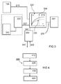
- Fig. 3 shows a schematic block diagram of an interconnection of different components of a hob 100 according to an embodiment of the present invention. Shown are an operating element 155, the input interface 220, a memory device 310, the protective device 210, an attention checking device 330 and the heating element 207.
- the input interface 220 and the memory unit 310 can be structurally integrated in one unit, which is indicated by the dashed line around the input interface 220 and the storage unit 310 is indicated.
- the operating element 155 is connected to the protective device 210.
- the control element 155 may be a conventional control element of a commercial hob, such as a knob for adjusting the temperature of a cooking zone.
- the precise configuration of the operating element 155 is of secondary importance for the purposes of the present invention, as long as a main user of the hob can select a desired energy supply to the associated heating element in the form of a control parameter 215 for the cooking zone by means of the operating element 155.
- This control parameter 215 is transmitted to the protection device 210.
- the input interface 220 is connected to the memory device 310.
- the input interface 220 includes a manual interface, an electronic interface or a combination of a manual interface and an electronic interface.
- the input interface 220 may be configured similar to the operating element 155, for example as a rotary knob, input key or as a plug connection for an electronic device, wherein the input interface 220 is arranged separately from the operating element 155.
- the exact configuration of the input interface 220 is not central to the purposes of the present invention, as long as a user of the hob, in particular a different person from the main user, can select or set at least one modification parameter 227 by means of the input interface 220. This at least one modification parameter 227 is transmitted to the memory device 310.
- the input interface 220 is connected to the memory device 310 on the one hand and to the protective device 210 on the other hand. From the memory device 310, the modification parameter 227 can be retrieved by the protection device 210.
- the memory device 310 may be any suitable memory device known in the art, such as an FPGA, an EEPROM, a flash memory, or other electronically programmable device. In the memory device 310, for example, by an electronic input a course of different modification parameters are stored, which maps an energy supply to the heating element for different control parameters.
- a modification of the control parameter can take place in the protective device 210 such that a desired setpoint temperature T is entered by the control parameter 215, which corresponds to an operating point on the course drawn in the diagram 332, so that an associated energy supply H to the heating element 207 is required for this would. Since now the user of the hob has only a limited ability to perceive, this energy can already cause the stove emanate considerable risks.
- the control unit 215 is modified in the protection unit 210 in such a way that the temperature T of the heating element is only one more in Fig. 3 dashed maximum temperature 334 can assume, so that it can no longer come to the aforementioned dangers due to a too hot cooking zone.
- a temperature increase of the heating element or the cooking zone can be reduced, for example, if the modified control parameter represents an energy supply H to the heating element 207, which instead of on the solid curve in Fig. 3 on the in Fig. 3 dashed lines shown for a reduced temporal temperature increase 335. In this case, a lower energy H than the actual desired by the control parameter 215 user input H to the heating element 207 is allowed, so that consequently the temperature rise of the heating element 207 is lower.
- the characteristic curve for the defined reduced temperature rise 335 can be carried out, for example, by multiplying the control parameter 215 by a factor of less than one, this factor being in the range of Control parameters that represent a low temperature T of the heating element 207 may be greater than for a control parameter representing a higher temperature T of the heating element 207.
- this modified control parameter 230 a supply of energy by the heating element 207 is controlled or regulated such that the heating element 207 outputs a heating power, a temperature or a temperature increase corresponding to the modified control parameter 230 to a cookware such as a pot or a pan the hob above the heating element 207 is located.
- the attention checking device 330 may optionally be provided.
- the attention checking device 330 is connected to the protection device 210. Although it is in Fig. 3 is not shown, the attention checking device 330 has suitable structures or subunits to determine a reaction time of a user of the hob.
- the attention checking device 330 outputs, for example, an audible and / or optical test signal 340 to the user and receives a reaction signal 350 by actuating, for example, a specially provided and in the Fig. 3 not shown switch by the user.
- the response time 360 in terms of the time delay between the output of the test signal 340 and the receipt of the response signal 350 transmits the attention checking device 330 to the protection device 210.
- the protection device 210 also reads out the response time 360 from the attention checking unit 330 in addition to the modification parameter 227 and additionally makes the determination of the modified control parameter 230 based on the determined response time 360. This makes it possible to monitor whether the user's abilities to monitor the cooktop have subsided, so that, if necessary, an automatic adaptation of the modification parameter is required. This adaptation can be done, for example, such that the modification parameter is changed so that the heating element may assume an even lower maximum temperature or the maximum allowable temperature rise of the heating element is further reduced.
- Fig. 4 13 shows a flowchart of a method 400 for controlling a power supply to a heating element 207 of a hob 110.
- the method 400 includes a step of receiving 410 at least one control parameter 215 for a heating element 207 Furthermore, the method comprises a step of reading 420 at least one modification parameter 227 from an input interface 220 and a step of determining 430 a modified control parameter 230 using the control parameter 215 and the modification parameter 227 Finally, the method 400 includes a step of outputting 440 the modified control parameter 230 to the heating element 207 for controlling a power supply of the heating element 207 of the hob 110 in order to control the heating element 207 such that the heating element 207 is heated at most up to a defined maximum temperature 334 or that the heating element 207 is heated at most with a defined temporal temperature gradient 335.
Landscapes
- Chemical & Material Sciences (AREA)
- Engineering & Computer Science (AREA)
- Ceramic Engineering (AREA)
- Physics & Mathematics (AREA)
- Electromagnetism (AREA)
- Electric Stoves And Ranges (AREA)
- Control Of Resistance Heating (AREA)
Applications Claiming Priority (1)
| Application Number | Priority Date | Filing Date | Title |
|---|---|---|---|
| DE201010064294 DE102010064294A1 (de) | 2010-12-29 | 2010-12-29 | Kochfeld und Verfahren zur Steuerung einer Energiezufuhr an ein Heizelement eines Kochfeldes |
Publications (2)
| Publication Number | Publication Date |
|---|---|
| EP2472999A1 true EP2472999A1 (fr) | 2012-07-04 |
| EP2472999B1 EP2472999B1 (fr) | 2016-03-16 |
Family
ID=45442882
Family Applications (1)
| Application Number | Title | Priority Date | Filing Date |
|---|---|---|---|
| EP11194251.2A Active EP2472999B1 (fr) | 2010-12-29 | 2011-12-19 | Champ de cuisson et procédé de commande de l'apport énergétique sur un élément de chauffe d'un champ de cuisson |
Country Status (3)
| Country | Link |
|---|---|
| EP (1) | EP2472999B1 (fr) |
| DE (1) | DE102010064294A1 (fr) |
| ES (1) | ES2565759T3 (fr) |
Cited By (4)
| Publication number | Priority date | Publication date | Assignee | Title |
|---|---|---|---|---|
| EP2704523B1 (fr) | 2012-09-03 | 2016-12-14 | BSH Hausgeräte GmbH | Dispositif de champ de cuisson à induction |
| CN109932930A (zh) * | 2017-12-15 | 2019-06-25 | 佛山市顺德区美的电热电器制造有限公司 | 加热控制方法、装置、加热器具和计算机可读存储介质 |
| EP3863372A1 (fr) * | 2020-02-10 | 2021-08-11 | E.G.O. Elektro-Gerätebau GmbH | Procédé de commande d'un dispositif chauffant d'une plaque de cuisson et plaque de cuisson |
| US11570853B2 (en) | 2021-02-01 | 2023-01-31 | E.G.O. Elektro-Geraetebau Gmbh | Method for actuating a heating device of a hob, and hob |
Families Citing this family (6)
| Publication number | Priority date | Publication date | Assignee | Title |
|---|---|---|---|---|
| DE102013215569B3 (de) * | 2013-08-07 | 2015-02-12 | E.G.O. Elektro-Gerätebau GmbH | Verfahren zur Steuerung einer Heizeinrichtung und Kochfeld |
| DE102014114961A1 (de) * | 2014-10-15 | 2016-04-21 | Rational Aktiengesellschaft | Gargerät sowie Verfahren zum Dokumentieren von Wartungsparametern eines Gargeräts |
| DE202022106277U1 (de) | 2022-11-09 | 2022-11-16 | Termacook Gmbh | Sensorgesteuertes Kochfeld |
| DE102022129549A1 (de) | 2022-11-09 | 2024-05-16 | Termacook Gmbh | Sensorgesteuertes Kochfeld |
| DE202023103051U1 (de) | 2023-06-02 | 2023-06-16 | Termacook Gmbh | Kochfeld mit integriertem Abzug und mit Beleuchtung, Verwendung des Kochfeldes zur Beleuchtung |
| DE102023114566A1 (de) | 2023-06-02 | 2024-12-05 | Termacook Gmbh | Kochfeld mit integriertem Abzug und mit Beleuchtung, Verwendung des Kochfeldes zur Beleuchtung |
Citations (5)
| Publication number | Priority date | Publication date | Assignee | Title |
|---|---|---|---|---|
| US4394564A (en) * | 1981-12-21 | 1983-07-19 | General Electric Company | Solid plate heating unit |
| US4740664A (en) * | 1987-01-05 | 1988-04-26 | General Electric Company | Temperature limiting arrangement for a glass-ceramic cooktop appliance |
| DE4336752A1 (de) * | 1993-10-28 | 1995-05-04 | Daimler Benz Ag | Verfahren zum Anpassen der elektrischen Heizleistung an die zur Speisenzubereitung erforderlichen Kenngrößen |
| US6285012B1 (en) * | 2000-09-06 | 2001-09-04 | General Electric Company | Method and apparatus for thermal limiting of the temperature of a glass-ceramic cooktop |
| US6350968B1 (en) * | 2000-10-16 | 2002-02-26 | General Electric Company | Method and apparatus for rapid heat-up of a glass-ceramic cooktop |
-
2010
- 2010-12-29 DE DE201010064294 patent/DE102010064294A1/de not_active Withdrawn
-
2011
- 2011-12-19 EP EP11194251.2A patent/EP2472999B1/fr active Active
- 2011-12-19 ES ES11194251.2T patent/ES2565759T3/es active Active
Patent Citations (5)
| Publication number | Priority date | Publication date | Assignee | Title |
|---|---|---|---|---|
| US4394564A (en) * | 1981-12-21 | 1983-07-19 | General Electric Company | Solid plate heating unit |
| US4740664A (en) * | 1987-01-05 | 1988-04-26 | General Electric Company | Temperature limiting arrangement for a glass-ceramic cooktop appliance |
| DE4336752A1 (de) * | 1993-10-28 | 1995-05-04 | Daimler Benz Ag | Verfahren zum Anpassen der elektrischen Heizleistung an die zur Speisenzubereitung erforderlichen Kenngrößen |
| US6285012B1 (en) * | 2000-09-06 | 2001-09-04 | General Electric Company | Method and apparatus for thermal limiting of the temperature of a glass-ceramic cooktop |
| US6350968B1 (en) * | 2000-10-16 | 2002-02-26 | General Electric Company | Method and apparatus for rapid heat-up of a glass-ceramic cooktop |
Cited By (6)
| Publication number | Priority date | Publication date | Assignee | Title |
|---|---|---|---|---|
| EP2704523B1 (fr) | 2012-09-03 | 2016-12-14 | BSH Hausgeräte GmbH | Dispositif de champ de cuisson à induction |
| EP2704523B2 (fr) † | 2012-09-03 | 2019-12-18 | BSH Hausgeräte GmbH | Dispositif de champ de cuisson à induction |
| CN109932930A (zh) * | 2017-12-15 | 2019-06-25 | 佛山市顺德区美的电热电器制造有限公司 | 加热控制方法、装置、加热器具和计算机可读存储介质 |
| CN109932930B (zh) * | 2017-12-15 | 2021-07-20 | 佛山市顺德区美的电热电器制造有限公司 | 加热控制方法、装置、加热器具和计算机可读存储介质 |
| EP3863372A1 (fr) * | 2020-02-10 | 2021-08-11 | E.G.O. Elektro-Gerätebau GmbH | Procédé de commande d'un dispositif chauffant d'une plaque de cuisson et plaque de cuisson |
| US11570853B2 (en) | 2021-02-01 | 2023-01-31 | E.G.O. Elektro-Geraetebau Gmbh | Method for actuating a heating device of a hob, and hob |
Also Published As
| Publication number | Publication date |
|---|---|
| EP2472999B1 (fr) | 2016-03-16 |
| DE102010064294A1 (de) | 2012-07-05 |
| ES2565759T3 (es) | 2016-04-06 |
Similar Documents
| Publication | Publication Date | Title |
|---|---|---|
| EP2472999B1 (fr) | Champ de cuisson et procédé de commande de l'apport énergétique sur un élément de chauffe d'un champ de cuisson | |
| DE69309896T2 (de) | Kochherd mit automatischer regelung | |
| EP3489583B1 (fr) | Procédé de commande d'un appareil de cuisson doté d'un appareil de commande externe, appareil de cuisson et système | |
| DE2935862C2 (de) | Mittels Sensor gesteuerter Koch- und Bratherd | |
| EP2510413A1 (fr) | Procédé de commande d'un processus de cuisson | |
| EP3489584A1 (fr) | Procédé de commande d'un appareil de cuisson doté d'un appareil de commande externe, appareil de cuisson et système | |
| EP1391141B1 (fr) | Procede et dispositif pour limiter et/ou reguler la temperature superficielle d'une plaque de cuisson | |
| DE3026620A1 (de) | Kochreguliereinrichtung | |
| DE102010005655B4 (de) | Verfahren zum Betrieb eines elektronisch gesteuerten Gaskochgerätes und elektronisch gesteuertes Gaskochgerät | |
| EP1037508A1 (fr) | Cuisinière à induction possédant une régulation en température | |
| DE19802558A1 (de) | Steuerung für ein Elektrowärmegerät | |
| EP2837890A2 (fr) | Procédé de fonctionnement d'un four de cuisson à gaz et four de cuisson à gaz | |
| DE102016110232A1 (de) | Überwachungssystem für eine Saunakabine, insbesondere zum Brandschutz und Saunakabine mit einem derartigen Überwachungssystem | |
| EP1600694B1 (fr) | Dispositif et méthode de commande et d'affichage à temps d'un appareil de ménage | |
| EP3603466B1 (fr) | Dispositif de régulation de la température d'un gril, en particulier d'un gril à gaz | |
| DE19501273A1 (de) | Vorrichtung als Schaltuhr zur Steuerung und/oder Sicherung eines elektrischen Gerätes, wie z. B. eines Herdes od.dgl. | |
| DE69512466T2 (de) | Einrichtung zur Programmierung für ein Haushaltgaskochgerät | |
| DE19851029C2 (de) | Verfahren zum Anpassen des Grenzwertes der Betriebstemperatur einer Glas-/Glaskeramikkochfläche und Vorrichtung zur Durchführung des Verfahrens | |
| DE102012200342B4 (de) | Verfahren zur Ansteuerung mehrerer Gasbrenner eines Gaskochfeldes | |
| EP3816517A1 (fr) | Commande d'appareil de cuisson comprenant un sélecteur de fonctionnement et de minuterie | |
| EP1462725B1 (fr) | Appareil de cuisson, en particulier four de cuisson avec au moins un brûleur à gaz | |
| DE102014215776A1 (de) | Verfahren zum Beschleunigen eines Kochvorgangs, Steuereinrichtung sowie Gargerät hierfür | |
| DE10132789A1 (de) | Gargerät | |
| DE102012201808A1 (de) | Kochfeldanordnung, Tisch mit einer Kochfeldanordnung und Verfahren zum Betreiben einer Kochfeldanordnung | |
| DE202022102916U1 (de) | Vorrichtung und Adapter für die Vorrichtung zur Regelung der Temperatur eines Grills, insbesondere eines Gasgrills |
Legal Events
| Date | Code | Title | Description |
|---|---|---|---|
| AK | Designated contracting states |
Kind code of ref document: A1 Designated state(s): AL AT BE BG CH CY CZ DE DK EE ES FI FR GB GR HR HU IE IS IT LI LT LU LV MC MK MT NL NO PL PT RO RS SE SI SK SM TR |
|
| AX | Request for extension of the european patent |
Extension state: BA ME |
|
| PUAI | Public reference made under article 153(3) epc to a published international application that has entered the european phase |
Free format text: ORIGINAL CODE: 0009012 |
|
| 17P | Request for examination filed |
Effective date: 20130104 |
|
| RAP1 | Party data changed (applicant data changed or rights of an application transferred) |
Owner name: BSH HAUSGERAETE GMBH |
|
| RIC1 | Information provided on ipc code assigned before grant |
Ipc: H05B 1/02 20060101AFI20150625BHEP Ipc: H05B 11/00 20060101ALI20150625BHEP Ipc: H05B 3/74 20060101ALI20150625BHEP Ipc: H05B 6/06 20060101ALI20150625BHEP |
|
| GRAP | Despatch of communication of intention to grant a patent |
Free format text: ORIGINAL CODE: EPIDOSNIGR1 |
|
| INTG | Intention to grant announced |
Effective date: 20150916 |
|
| GRAS | Grant fee paid |
Free format text: ORIGINAL CODE: EPIDOSNIGR3 |
|
| GRAA | (expected) grant |
Free format text: ORIGINAL CODE: 0009210 |
|
| AK | Designated contracting states |
Kind code of ref document: B1 Designated state(s): AL AT BE BG CH CY CZ DE DK EE ES FI FR GB GR HR HU IE IS IT LI LT LU LV MC MK MT NL NO PL PT RO RS SE SI SK SM TR |
|
| REG | Reference to a national code |
Ref country code: GB Ref legal event code: FG4D Free format text: NOT ENGLISH |
|
| REG | Reference to a national code |
Ref country code: CH Ref legal event code: EP |
|
| REG | Reference to a national code |
Ref country code: ES Ref legal event code: FG2A Ref document number: 2565759 Country of ref document: ES Kind code of ref document: T3 Effective date: 20160406 Ref country code: IE Ref legal event code: FG4D Free format text: LANGUAGE OF EP DOCUMENT: GERMAN |
|
| REG | Reference to a national code |
Ref country code: AT Ref legal event code: REF Ref document number: 782150 Country of ref document: AT Kind code of ref document: T Effective date: 20160415 |
|
| REG | Reference to a national code |
Ref country code: DE Ref legal event code: R096 Ref document number: 502011009094 Country of ref document: DE |
|
| REG | Reference to a national code |
Ref country code: NL Ref legal event code: MP Effective date: 20160316 |
|
| REG | Reference to a national code |
Ref country code: LT Ref legal event code: MG4D |
|
| PG25 | Lapsed in a contracting state [announced via postgrant information from national office to epo] |
Ref country code: GR Free format text: LAPSE BECAUSE OF FAILURE TO SUBMIT A TRANSLATION OF THE DESCRIPTION OR TO PAY THE FEE WITHIN THE PRESCRIBED TIME-LIMIT Effective date: 20160617 Ref country code: HR Free format text: LAPSE BECAUSE OF FAILURE TO SUBMIT A TRANSLATION OF THE DESCRIPTION OR TO PAY THE FEE WITHIN THE PRESCRIBED TIME-LIMIT Effective date: 20160316 Ref country code: FI Free format text: LAPSE BECAUSE OF FAILURE TO SUBMIT A TRANSLATION OF THE DESCRIPTION OR TO PAY THE FEE WITHIN THE PRESCRIBED TIME-LIMIT Effective date: 20160316 Ref country code: NO Free format text: LAPSE BECAUSE OF FAILURE TO SUBMIT A TRANSLATION OF THE DESCRIPTION OR TO PAY THE FEE WITHIN THE PRESCRIBED TIME-LIMIT Effective date: 20160616 |
|
| PG25 | Lapsed in a contracting state [announced via postgrant information from national office to epo] |
Ref country code: SE Free format text: LAPSE BECAUSE OF FAILURE TO SUBMIT A TRANSLATION OF THE DESCRIPTION OR TO PAY THE FEE WITHIN THE PRESCRIBED TIME-LIMIT Effective date: 20160316 Ref country code: NL Free format text: LAPSE BECAUSE OF FAILURE TO SUBMIT A TRANSLATION OF THE DESCRIPTION OR TO PAY THE FEE WITHIN THE PRESCRIBED TIME-LIMIT Effective date: 20160316 Ref country code: LV Free format text: LAPSE BECAUSE OF FAILURE TO SUBMIT A TRANSLATION OF THE DESCRIPTION OR TO PAY THE FEE WITHIN THE PRESCRIBED TIME-LIMIT Effective date: 20160316 Ref country code: LT Free format text: LAPSE BECAUSE OF FAILURE TO SUBMIT A TRANSLATION OF THE DESCRIPTION OR TO PAY THE FEE WITHIN THE PRESCRIBED TIME-LIMIT Effective date: 20160316 Ref country code: RS Free format text: LAPSE BECAUSE OF FAILURE TO SUBMIT A TRANSLATION OF THE DESCRIPTION OR TO PAY THE FEE WITHIN THE PRESCRIBED TIME-LIMIT Effective date: 20160316 |
|
| PG25 | Lapsed in a contracting state [announced via postgrant information from national office to epo] |
Ref country code: IS Free format text: LAPSE BECAUSE OF FAILURE TO SUBMIT A TRANSLATION OF THE DESCRIPTION OR TO PAY THE FEE WITHIN THE PRESCRIBED TIME-LIMIT Effective date: 20160716 Ref country code: EE Free format text: LAPSE BECAUSE OF FAILURE TO SUBMIT A TRANSLATION OF THE DESCRIPTION OR TO PAY THE FEE WITHIN THE PRESCRIBED TIME-LIMIT Effective date: 20160316 Ref country code: PL Free format text: LAPSE BECAUSE OF FAILURE TO SUBMIT A TRANSLATION OF THE DESCRIPTION OR TO PAY THE FEE WITHIN THE PRESCRIBED TIME-LIMIT Effective date: 20160316 |
|
| PG25 | Lapsed in a contracting state [announced via postgrant information from national office to epo] |
Ref country code: SM Free format text: LAPSE BECAUSE OF FAILURE TO SUBMIT A TRANSLATION OF THE DESCRIPTION OR TO PAY THE FEE WITHIN THE PRESCRIBED TIME-LIMIT Effective date: 20160316 Ref country code: RO Free format text: LAPSE BECAUSE OF FAILURE TO SUBMIT A TRANSLATION OF THE DESCRIPTION OR TO PAY THE FEE WITHIN THE PRESCRIBED TIME-LIMIT Effective date: 20160316 Ref country code: CZ Free format text: LAPSE BECAUSE OF FAILURE TO SUBMIT A TRANSLATION OF THE DESCRIPTION OR TO PAY THE FEE WITHIN THE PRESCRIBED TIME-LIMIT Effective date: 20160316 Ref country code: SK Free format text: LAPSE BECAUSE OF FAILURE TO SUBMIT A TRANSLATION OF THE DESCRIPTION OR TO PAY THE FEE WITHIN THE PRESCRIBED TIME-LIMIT Effective date: 20160316 Ref country code: PT Free format text: LAPSE BECAUSE OF FAILURE TO SUBMIT A TRANSLATION OF THE DESCRIPTION OR TO PAY THE FEE WITHIN THE PRESCRIBED TIME-LIMIT Effective date: 20160718 |
|
| REG | Reference to a national code |
Ref country code: DE Ref legal event code: R097 Ref document number: 502011009094 Country of ref document: DE |
|
| REG | Reference to a national code |
Ref country code: FR Ref legal event code: PLFP Year of fee payment: 6 |
|
| PLBE | No opposition filed within time limit |
Free format text: ORIGINAL CODE: 0009261 |
|
| STAA | Information on the status of an ep patent application or granted ep patent |
Free format text: STATUS: NO OPPOSITION FILED WITHIN TIME LIMIT |
|
| PG25 | Lapsed in a contracting state [announced via postgrant information from national office to epo] |
Ref country code: DK Free format text: LAPSE BECAUSE OF FAILURE TO SUBMIT A TRANSLATION OF THE DESCRIPTION OR TO PAY THE FEE WITHIN THE PRESCRIBED TIME-LIMIT Effective date: 20160316 |
|
| 26N | No opposition filed |
Effective date: 20161219 |
|
| PG25 | Lapsed in a contracting state [announced via postgrant information from national office to epo] |
Ref country code: BG Free format text: LAPSE BECAUSE OF FAILURE TO SUBMIT A TRANSLATION OF THE DESCRIPTION OR TO PAY THE FEE WITHIN THE PRESCRIBED TIME-LIMIT Effective date: 20160616 |
|
| PG25 | Lapsed in a contracting state [announced via postgrant information from national office to epo] |
Ref country code: BE Free format text: LAPSE BECAUSE OF NON-PAYMENT OF DUE FEES Effective date: 20161231 Ref country code: SI Free format text: LAPSE BECAUSE OF FAILURE TO SUBMIT A TRANSLATION OF THE DESCRIPTION OR TO PAY THE FEE WITHIN THE PRESCRIBED TIME-LIMIT Effective date: 20160316 |
|
| REG | Reference to a national code |
Ref country code: CH Ref legal event code: PL |
|
| PG25 | Lapsed in a contracting state [announced via postgrant information from national office to epo] |
Ref country code: MC Free format text: LAPSE BECAUSE OF FAILURE TO SUBMIT A TRANSLATION OF THE DESCRIPTION OR TO PAY THE FEE WITHIN THE PRESCRIBED TIME-LIMIT Effective date: 20160316 |
|
| REG | Reference to a national code |
Ref country code: IE Ref legal event code: MM4A |
|
| PG25 | Lapsed in a contracting state [announced via postgrant information from national office to epo] |
Ref country code: LI Free format text: LAPSE BECAUSE OF NON-PAYMENT OF DUE FEES Effective date: 20161231 Ref country code: LU Free format text: LAPSE BECAUSE OF NON-PAYMENT OF DUE FEES Effective date: 20161219 Ref country code: CH Free format text: LAPSE BECAUSE OF NON-PAYMENT OF DUE FEES Effective date: 20161231 |
|
| PG25 | Lapsed in a contracting state [announced via postgrant information from national office to epo] |
Ref country code: IE Free format text: LAPSE BECAUSE OF NON-PAYMENT OF DUE FEES Effective date: 20161219 |
|
| REG | Reference to a national code |
Ref country code: FR Ref legal event code: PLFP Year of fee payment: 7 |
|
| REG | Reference to a national code |
Ref country code: BE Ref legal event code: MM Effective date: 20161231 |
|
| REG | Reference to a national code |
Ref country code: AT Ref legal event code: MM01 Ref document number: 782150 Country of ref document: AT Kind code of ref document: T Effective date: 20161219 |
|
| PG25 | Lapsed in a contracting state [announced via postgrant information from national office to epo] |
Ref country code: HU Free format text: LAPSE BECAUSE OF FAILURE TO SUBMIT A TRANSLATION OF THE DESCRIPTION OR TO PAY THE FEE WITHIN THE PRESCRIBED TIME-LIMIT; INVALID AB INITIO Effective date: 20111219 Ref country code: CY Free format text: LAPSE BECAUSE OF FAILURE TO SUBMIT A TRANSLATION OF THE DESCRIPTION OR TO PAY THE FEE WITHIN THE PRESCRIBED TIME-LIMIT Effective date: 20160316 Ref country code: AT Free format text: LAPSE BECAUSE OF NON-PAYMENT OF DUE FEES Effective date: 20161219 |
|
| PG25 | Lapsed in a contracting state [announced via postgrant information from national office to epo] |
Ref country code: MK Free format text: LAPSE BECAUSE OF FAILURE TO SUBMIT A TRANSLATION OF THE DESCRIPTION OR TO PAY THE FEE WITHIN THE PRESCRIBED TIME-LIMIT Effective date: 20160316 |
|
| PG25 | Lapsed in a contracting state [announced via postgrant information from national office to epo] |
Ref country code: MT Free format text: LAPSE BECAUSE OF FAILURE TO SUBMIT A TRANSLATION OF THE DESCRIPTION OR TO PAY THE FEE WITHIN THE PRESCRIBED TIME-LIMIT Effective date: 20160316 |
|
| PG25 | Lapsed in a contracting state [announced via postgrant information from national office to epo] |
Ref country code: AL Free format text: LAPSE BECAUSE OF FAILURE TO SUBMIT A TRANSLATION OF THE DESCRIPTION OR TO PAY THE FEE WITHIN THE PRESCRIBED TIME-LIMIT Effective date: 20160316 |
|
| PGFP | Annual fee paid to national office [announced via postgrant information from national office to epo] |
Ref country code: IT Payment date: 20191216 Year of fee payment: 9 |
|
| PGFP | Annual fee paid to national office [announced via postgrant information from national office to epo] |
Ref country code: GB Payment date: 20191220 Year of fee payment: 9 |
|
| GBPC | Gb: european patent ceased through non-payment of renewal fee |
Effective date: 20201219 |
|
| PG25 | Lapsed in a contracting state [announced via postgrant information from national office to epo] |
Ref country code: IT Free format text: LAPSE BECAUSE OF NON-PAYMENT OF DUE FEES Effective date: 20201219 |
|
| PG25 | Lapsed in a contracting state [announced via postgrant information from national office to epo] |
Ref country code: GB Free format text: LAPSE BECAUSE OF NON-PAYMENT OF DUE FEES Effective date: 20201219 |
|
| PGFP | Annual fee paid to national office [announced via postgrant information from national office to epo] |
Ref country code: FR Payment date: 20221219 Year of fee payment: 12 |
|
| REG | Reference to a national code |
Ref country code: DE Ref legal event code: R084 Ref document number: 502011009094 Country of ref document: DE |
|
| PGFP | Annual fee paid to national office [announced via postgrant information from national office to epo] |
Ref country code: TR Payment date: 20221219 Year of fee payment: 12 Ref country code: ES Payment date: 20230119 Year of fee payment: 12 |
|
| PG25 | Lapsed in a contracting state [announced via postgrant information from national office to epo] |
Ref country code: FR Free format text: LAPSE BECAUSE OF NON-PAYMENT OF DUE FEES Effective date: 20231231 |
|
| PG25 | Lapsed in a contracting state [announced via postgrant information from national office to epo] |
Ref country code: FR Free format text: LAPSE BECAUSE OF NON-PAYMENT OF DUE FEES Effective date: 20231231 |
|
| REG | Reference to a national code |
Ref country code: ES Ref legal event code: FD2A Effective date: 20250131 |
|
| PG25 | Lapsed in a contracting state [announced via postgrant information from national office to epo] |
Ref country code: ES Free format text: LAPSE BECAUSE OF NON-PAYMENT OF DUE FEES Effective date: 20231220 |
|
| PGFP | Annual fee paid to national office [announced via postgrant information from national office to epo] |
Ref country code: DE Payment date: 20251231 Year of fee payment: 15 |