EP2473000A1 - Kochfeldvorrichtung - Google Patents
Kochfeldvorrichtung Download PDFInfo
- Publication number
- EP2473000A1 EP2473000A1 EP11194740A EP11194740A EP2473000A1 EP 2473000 A1 EP2473000 A1 EP 2473000A1 EP 11194740 A EP11194740 A EP 11194740A EP 11194740 A EP11194740 A EP 11194740A EP 2473000 A1 EP2473000 A1 EP 2473000A1
- Authority
- EP
- European Patent Office
- Prior art keywords
- cooking zone
- radius
- cooking
- temperature sensors
- heating unit
- Prior art date
- Legal status (The legal status is an assumption and is not a legal conclusion. Google has not performed a legal analysis and makes no representation as to the accuracy of the status listed.)
- Withdrawn
Links
- 238000010411 cooking Methods 0.000 claims abstract description 119
- 238000010438 heat treatment Methods 0.000 claims abstract description 71
- 230000006698 induction Effects 0.000 claims description 32
- 230000005291 magnetic effect Effects 0.000 description 5
- 230000008878 coupling Effects 0.000 description 2
- 238000010168 coupling process Methods 0.000 description 2
- 238000005859 coupling reaction Methods 0.000 description 2
- 230000001419 dependent effect Effects 0.000 description 2
- 239000000463 material Substances 0.000 description 2
- 230000005294 ferromagnetic effect Effects 0.000 description 1
- 239000003550 marker Substances 0.000 description 1
- 238000000034 method Methods 0.000 description 1
- 238000012986 modification Methods 0.000 description 1
- 230000004048 modification Effects 0.000 description 1
Images

Classifications
-
- H—ELECTRICITY
- H05—ELECTRIC TECHNIQUES NOT OTHERWISE PROVIDED FOR
- H05B—ELECTRIC HEATING; ELECTRIC LIGHT SOURCES NOT OTHERWISE PROVIDED FOR; CIRCUIT ARRANGEMENTS FOR ELECTRIC LIGHT SOURCES, IN GENERAL
- H05B3/00—Ohmic-resistance heating
- H05B3/68—Heating arrangements specially adapted for cooking plates or analogous hot-plates
- H05B3/74—Non-metallic plates, e.g. vitroceramic, ceramic or glassceramic hobs, also including power or control circuits
-
- H—ELECTRICITY
- H05—ELECTRIC TECHNIQUES NOT OTHERWISE PROVIDED FOR
- H05B—ELECTRIC HEATING; ELECTRIC LIGHT SOURCES NOT OTHERWISE PROVIDED FOR; CIRCUIT ARRANGEMENTS FOR ELECTRIC LIGHT SOURCES, IN GENERAL
- H05B6/00—Heating by electric, magnetic or electromagnetic fields
- H05B6/02—Induction heating
- H05B6/06—Control, e.g. of temperature, of power
- H05B6/062—Control, e.g. of temperature, of power for cooking plates or the like
-
- H—ELECTRICITY
- H05—ELECTRIC TECHNIQUES NOT OTHERWISE PROVIDED FOR
- H05B—ELECTRIC HEATING; ELECTRIC LIGHT SOURCES NOT OTHERWISE PROVIDED FOR; CIRCUIT ARRANGEMENTS FOR ELECTRIC LIGHT SOURCES, IN GENERAL
- H05B2213/00—Aspects relating both to resistive heating and to induction heating, covered by H05B3/00 and H05B6/00
- H05B2213/07—Heating plates with temperature control means
Definitions
- the invention relates to a hob device according to the preamble of claim 1.
- a cooktop having a cooking zone having four temperature sensors for determining a cooktop temperature, wherein one of the temperature sensors is located at a center and the other temperature sensors are located in an edge region of the cooking zone.
- the object of the invention is, in particular, to provide a generic device with improved temperature determination and enabled component savings.
- the object is achieved by the features of claim 1, while advantageous embodiments and modifications of the invention can be taken from the dependent claims.
- the invention is based on a hob device having at least one cooking zone and at least one heating unit associated with the cooking zone and at least two, preferably at least three, temperature sensors associated with the cooking zone.
- each of the cooking zone associated temperature sensor has a distance to a center of the cooking zone, which is at least as large as a minimum radius corresponding to at least 10%, more preferably at least 20% and preferably at least 25% of the radius of the cooking zone associated heating unit ,
- a "cooking zone” is to be understood as meaning a limited area, in particular a region of a hob plate, on which preferably a cooking utensil can be placed for heating and / or heating.
- the boundary of the surface is designed to be visible to an operator, which serves at least to display an operator a maximum harness size that can be sensibly heated with the associated heating unit.
- a “heating unit” assigned to the cooking zone is to be understood in particular to mean a unit which is intended to heat and / or to supply a cooking utensil placed on the cooking zone heat.
- a heating unit has at least one heating element.
- a heating element may in particular be designed as an induction heating element, radiant heating element and / or resistance heating element.
- a "temperature sensor” should in particular be understood as meaning a sensor which has at least one temperature-dependent parameter measurable by a measuring unit whose value can be uniquely assigned to a temperature within a temperature range of preferably 0 ° C. to 250 ° C.
- the characteristic is an electrical resistance, preferably an NTC resistor.
- An NTC resistor is at least partially formed by at least one material, preferably a semiconductive material, with negative electrical temperature coefficients and has a higher resistance at low temperatures than at high temperatures.
- the temperature sensors are preferably arranged on a lower side of the hob plate below the cooking zone. In principle, however, arrangements outside the cooking zone, in particular between two cooking zones, are conceivable.
- the temperature sensors are provided for a determination of a Gargeschirrtemperatur.
- a "distance" of a temperature sensor to the center of the cooking zone should be understood in particular a minimum of the distances of all points of the temperature sensor to the center.
- a “center point” of the cooking zone is to be understood in particular to be the point of the cooking zone whose mean square distance to each point of the boundary of the cooking zone is minimal.
- the center of the cooking zone is a point cut by a straight line perpendicular to the surface of the cooking zone and intersecting the center of the heating unit.
- a “center point” or a “radius” of the heating unit is to be understood in particular as meaning a center or a radius of a smallest circle, which is oriented in particular parallel to a surface of the cooking zone, which completely surrounds the heating unit.
- Garderobe floors usually have a curvature, which leads to better heat contact with the cooktop panel in an edge region of the cooking dish than in the center of the cooking dish floor.
- the at least two, preferably at least three, temperature sensors have at least two, preferably at least three, different distances to the center of the cooking zone.
- any two adjacent follower elements of an ordered sequence of the different distances of the at least two, preferably at least three, temperature sensors to the center have a difference which is a maximum of 20 mm, in particular a maximum of 15 mm and preferably a maximum of 12 mm.
- the distances between adjacent followers are the same size.
- at least one temperature sensor has a distance to the center of the cooking zone, which lies in a range from the minimum radius to a radius which is 2 cm larger than the minimum radius.
- At least one temperature sensor is arranged at a distance of less than 2 cm from the cooking zone boundary.
- two spacings "differ” if they have a difference which is greater than 2 mm, in particular greater than 5 mm and advantageously greater than 8 mm.
- a high degree of flexibility with regard to a size of a cooking utensil used is achieved.
- the heating unit is designed as an induction heating unit with at least one induction heating element.
- the induction heating element is preferably designed as an electrical coil which generates an alternating magnetic field during operation of the heating unit.
- the alternating magnetic field transmits energy which is converted into heat in the bottom of the cooking utensil.
- the induction heating unit is powered by a power controlled power supply unit.
- the power supply unit has a current limiting unit, which avoids damage to the hob device. In particular, a long service life of the temperature sensors can be achieved because in an induction hob direct heat load is avoided by the heating unit.
- the minimum radius is at least as large as 50% of the radius of a smallest cookware usable with the induction heating unit.
- the minimum radius is 2 cm smaller than the radius of the smallest cookware usable with the induction heating unit.
- a radius of the cooking utensil is understood in particular to mean a radius of the circle which has the same surface area as the bottom of the cooking utensil.
- a cooking utensil is then "usable" with the induction heating unit if it has such a large magnetic coupling factor that, for an operator adjustable heating capacity greater than 50%, in particular greater than 70% and preferably greater than 90% of one maximum operator adjustable heating power, current limiting by the current limiting unit is unnecessary.
- a "magnetic coupling factor” is a parameter of the cooking utensil used, which describes together with a current flowing through the induction heating a current transmitted to the cooking heat and in particular depends on the size of the pot bottom.
- the smallest usable cooking utensil size associated with an induction heating unit is determined in particular by tests.
- the radius of the smallest usable pot is 4 cm at a radius of the induction heating unit of 7.5 cm, or 6.5 cm at 9 cm and 7.5 cm at 10.5 cm.
- a mark is arranged in the cooking zone, which reflects the smallest Garware size usable with the built-in induction heating unit.
- the at least two temperature sensors are arranged on a straight line which intersects the center of the cooking zone.
- a simple, space-saving wiring can be achieved.
- the center of the cooking zone is located between the at least two temperature sensors.
- a robustness with regard to a decentralized positioning of the cooking utensil can be made possible.
- the hob device has at least two different cooking zone radii, each of which is assigned a differing number of temperature sensors.
- Under a cooking zone radius is in particular a distance between the center of the cooking zone and a Be understood limiting point of the boundary of the cooking zone, wherein a boundary of the cooking zone of a circle or from a non-circular shape may be formed.
- a large circular cooking zone has at least as many temperature sensors as a small circular cooking zone.
- a cooking zone is designed as a roasting zone.
- a roasting zone has a shape which is larger in one spatial direction than in another.
- more sensors are arranged along a straight line which extends along a spatial direction which has a large extension of the cooking zone, than on a straight line which extends along a spatial direction in which the cooking zone has a small extension.
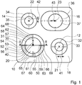
- the FIG. 1 shows a cooktop device with four cooking zones 10, 12, 14, 16, which are arranged on a cooktop plate 18.
- a boundary of the cooking zone 10, 12, 14, 16 on the hob plate 18 is marked with a mark 30, 32, 34, 36.
- the cooking zone 10 is associated with a heating unit 11 (see. FIG. 2 ).
- the heating unit 11 has a radius 13 of 10.5 cm.
- the cooking zone 10 is as large as the heating unit 11, which is arranged below it and has a radius 15 of 10.5 cm.
- the cooking zone 10 are 20 temperature sensors 50, 51, 52, 53, 54, 55, 56, 57, 58, 59, 60, 61, 62, 63, 64, 65, 66, 67, 68, 69 assigned to a Bottom 19 of the hob plate 18 are arranged.
- Each of the 20 temperature sensors 50, 51, 52, 53, 54, 55, 56, 57, 58, 59, 60, 61, 62, 63, 64, 65, 66, 67, 68, 69 is at a distance from a center 20 the cooking zone 10, which is at least as large as a minimum radius 40.
- the minimum radius 40 is greater than 50% of the radius of the cooking zone 10 associated heating unit 11.
- the minimum radius 40 corresponds to 5.5 cm.
- the temperature sensors 50, 51, 52, 53, 54 have five different distances from the center 20. For each of the temperature sensors 50, 51, 52, 53, 54, there are three further temperature sensors 55, 56, 57 and 58, 59, 60 and 61, 62, 63 and 64, 65, 66 and 67, 68, 69, which are each arranged at the same distance from the center 20.
- the temperature sensors 50, 51, 52, 53, 54, 55, 56, 57, 58, 59, 60, 61, 62, 63, 64, 65, 66, 67, 68, 69 have a diameter 24 of 8 mm.
- the distances of the temperature sensors 50, 51, 52, 53, 54 to the center 20 of the cooking zone 10 each have a difference of 10 mm from each other.
- the heating unit 11 is formed as an induction heating unit 26.
- the induction heating unit 26 is associated with a power supply unit having a current limiting unit. With the induction unit 26, which has a radius of 10.5 cm, cooking utensils can be heated with a radius 17 of greater than 7.5 cm, with an intervention of the current limiting unit is unnecessary.
- the minimum radius 40 is set at 5.5 cm, a value 2 cm smaller than a radius 17 of the smallest cooking utensil usable with the induction unit 26.
- the radius 17 of the smallest cooking utensil usable with the induction unit 26 is 7.5 cm.
- On the hob plate 18 is marked with a marker 31, a size of the smallest usable with the induction heating unit cooking utensils.
- the temperature sensors 50, 51, 55, 56, 57, 58, 59, 60 have a distance to the center of the cooking zone, which is smaller than the radius 17 of the smallest usable with the induction heating unit 26 cookware.
- the temperature sensors 50, 51, 52, 53, 54, 55, 56, 57, 58, 59, 60, 61, 62, 63, 64, 65, 66, 67, 68, 69 are arranged on two straight lines which extend in cut a right angle in the center 20.
- the center 20 of the cooking zone 10 is located between the temperature sensors 50 and 51.
- the cooking zone 12 has a smaller radius than the cooking zone 10.
- a radius of the cooking zone 12 is 7.5 cm. It is associated with a trained as induction heating unit heating unit with a radius of 7.5 cm.
- the cooking zone 12 are associated with eight temperature sensors. Each of the eight temperature sensors has one Distance to a center 21 of the cooking zone 12, which is at least as large as a minimum radius 41. The minimum radius 41 is greater than 25% of the radius of the heating unit. The minimum radius 41 corresponds to 4 cm.
- the temperature sensors have four different distances to the center 21 of the cooking zone 12. There are two temperature sensors each, which have the same distance to the center 21. The distances of the temperature sensors to the center 21 of the cooking zone 12 each have a difference from each other of 12 mm.
- a radius of the smallest cookware heated by the induction heating unit is 4 cm.
- the minimum radius 41 is as large as 50% of this value, ie 2 cm and is thus 2 cm smaller than the radius of the smallest cookware that can be used with the heating unit.
- the radius of the smallest cooking utensil usable with the heating unit is indicated by a mark 33.
- Two temperature sensors have a distance to the center of the cooking zone 12, which is smaller than the radius of the smallest usable with the induction heating unit cookware.
- the temperature sensors are arranged on a straight line which intersects the center point 21.
- the center 21 is between two of the temperature sensors.
- the cooking zone 14 has the same radius as the cooking zone 12.
- the cooking zone 14 is associated with a formed as an induction heating unit heating unit whose radius corresponds to the heating unit of the cooking zone 12.
- the cooking zone 14 are associated with six temperature sensors. A distance of each of the temperature sensors to a center 22 of the cooking zone 14 is at least as large as a minimum radius 42.
- the minimum radius 42 is greater than 25% of the radius of the heating unit.
- the minimum radius 42 corresponds to 4 cm.
- the temperature sensors are arranged at six different distances from the center 22 of the cooking zone 14. A difference between the distances is 10 mm.
- a radius of the smallest cookware heated by the induction heating unit is 4 cm.
- the minimum radius 42 is as large as 50% of this value and is 2 cm.
- the radius of the smallest cooking utensil usable with the heating unit is indicated by a mark 35.
- Two temperature sensors have a distance to the center of the cooking zone that is smaller than the radius of the smallest cooking utensil usable with the induction heating unit.
- the temperature sensors are arranged on a straight line which intersects the center point 22.
- the center 22 is between two of the temperature sensors.
- the cooking zone 16 is formed as a roasting zone. It has a radius of 9 cm in its smallest extent and a radius of 14 cm in its largest extent.
- An associated, designed as an induction heating unit heating unit has an induction heating element with a radius of 9 cm.
- the cooking zone 16 has twelve temperature sensors associated with it. The distance of each of the temperature sensors to a center 23 of the cooking zone 16 is at least as large as a minimum radius 43. The minimum radius 43 is 50% of the radius of the heating element. The minimum radius 43 is 4.5 cm.
- the temperature sensors are arranged at six different distances from the center 23. A difference between the different distances is 12 mm. A radius, a smallest cookware that can be used with the heating unit, is 6.5 cm.
- the minimum radius 43 was correspondingly reduced by 2 cm and set to 4.5 cm.
- the radius of the smallest cooking utensil usable with the heating unit is indicated by a mark 37.
- the temperature sensors are arranged on two straight lines that intersect at the midpoint 23 at a right angle.
- the center 23 of the cooking zone 16 is between two of the temperature sensors. Eight of the temperature sensors lie on a straight line that is aligned along the largest extent of the roaster zone and that is assigned to the large radius. Four of the temperature sensors lie on a straight line aligned along the smallest extent of the roaster zone and associated with the small radius.
- each of the cooking zones 10, 12, 14, 16 there are temperature sensors 54, 67, 68, 69 which extend to the limit mark 30, 32, 34, 36 of the cooking zone 10, 12, 14, 16 or beyond.
Landscapes
- Chemical & Material Sciences (AREA)
- Engineering & Computer Science (AREA)
- Ceramic Engineering (AREA)
- Physics & Mathematics (AREA)
- Electromagnetism (AREA)
- Induction Heating Cooking Devices (AREA)
- Cookers (AREA)
- Baking, Grill, Roasting (AREA)
- Electric Stoves And Ranges (AREA)
Abstract
Die Erfindung geht aus von einer Kochfeldvorrichtung mit wenigstens einer Kochzone (10, 12, 14, 16) und mit zumindest einer der Kochzone (10, 12, 14, 16) zugeordneten Heizeinheit (11) und zumindest zwei der Kochzone (10, 12, 14, 16) zugeordneten Temperatursensoren (50, 51, 52, 53, 54, 55, 56, 57, 58, 59, 60, 61, 62, 63, 64, 65, 66, 67, 68, 69). Um eine Temperaturbestimmung zu verbessern und eine Bauteilersparnis zu ermöglichen, wird vorgeschlagen, dass jeder der Kochzone (10, 12, 14, 16) zugeordnete Temperatursensor (50, 51, 52, 53, 54, 55, 56, 57, 58, 59, 60, 61, 62, 63, 64, 65, 66, 67, 68, 69) einen Abstand zu einem Mittelpunkt (20, 21, 22, 23) der Kochzone (10, 12, 14, 16) aufweist, der zumindest so groß ist wie ein Minimalradius (40, 41, 42, 43), der wenigstens 10% des Radius (13) der der Kochzone (10, 12, 14, 16) zugeordneten Heizeinheit (11) entspricht.
Description
- Die Erfindung geht aus von einer Kochfeldvorrichtung nach dem Oberbegriff des Anspruchs 1.
- Aus der
DE 198 20 108 C2 ist ein Kochfeld mit einer Kochzone bekannt, die vier Temperatursensoren zu einer Bestimmung einer Kochfeldtemperatur aufweist, wobei einer der Temperatursensoren in einem Mittelpunkt und die anderen Temperatursensoren in einem Randbereich der Kochzone angeordnet sind. - Die Aufgabe der Erfindung besteht insbesondere darin, eine gattungsgemäße Vorrichtung mit verbesserter Temperaturbestimmung und ermöglichter Bauteilersparnis bereitzustellen. Die Aufgabe wird erfindungsgemäß durch die Merkmale des Patentanspruchs 1 gelöst, während vorteilhafte Ausgestaltungen und Weiterbildungen der Erfindung den Unteransprüchen entnommen werden können.
- Die Erfindung geht aus von einer Kochfeldvorrichtung mit wenigstens einer Kochzone und mit zumindest einer der Kochzone zugeordneten Heizeinheit und zumindest zwei, vorzugsweise zumindest drei, der Kochzone zugeordneten Temperatursensoren.
- Es wird vorgeschlagen, dass jeder der Kochzone zugeordnete Temperatursensor einen Abstand zu einem Mittelpunkt der Kochzone aufweist, der zumindest so groß ist wie ein Minimalradius, der wenigstens 10 %, insbesondere wenigstens 20 % und vorzugsweise wenigstens 25% des Radius der der Kochzone zugeordneten Heizeinheit entspricht. Unter einer "Kochzone" soll eine begrenzte Fläche, insbesondere ein Bereich einer Kochfeldplatte, verstanden werden, auf den vorzugsweise ein Gargeschirr zu einer Erwärmung und/oder Erhitzung aufgestellt werden kann. Vorzugsweise ist die Begrenzung der Fläche für einen Bediener sichtbar ausgeführt, was zumindest dazu dient, einem Bediener eine maximale Geschirrgröße anzuzeigen, die mit der zugeordneten Heizeinheit sinnvoll beheizt werden kann. Unter einer der Kochzone zugeordneten "Heizeinheit" soll insbesondere eine Einheit verstanden werden, die dazu vorgesehen ist, ein auf der Kochzone aufgestelltes Gargeschirr zu erwärmen und/oder zu erhitzen. Eine Heizeinheit weist dabei zumindest ein Heizelement auf. Ein Heizelement kann insbesondere als Induktionsheizelement, Strahlungsheizelement und/oder Widerstandsheizelement ausgebildet sein. Unter einem "Temperatursensor" soll insbesondere ein Sensor verstanden werden, der zumindest eine, von einer Messeinheit messbare, temperaturabhängige Kenngröße aufweist, deren Wert in einem Temperaturbereich von vorzugsweise 0 °C bis 250 °C eineindeutig einer Temperatur zugeordnet werden kann. Vorzugsweise handelt es sich bei der Kenngröße um einen elektrischen Widerstand vorzugsweise eines NTC-Widerstands. Ein NTC-Widerstand ist dabei zumindest teilweise von zumindest einem Material, vorzugsweise einem halbleitenden Material, mit negativen elektrischen Temperaturkoeffizienten gebildet und weist bei niedrigen Temperaturen einen höheren Widerstand auf, als bei hohen Temperaturen. Insbesondere sind die Temperatursensoren an einer Unterseite der Kochfeldplatte vorzugsweise unterhalb der Kochzone angeordnet. Grundsätzlich sind jedoch auch Anordnungen außerhalb der Kochzone, insbesondere zwischen zwei Kochzonen, denkbar. Vorzugsweise sind die Temperatursensoren zu einer Bestimmung einer Gargeschirrtemperatur vorgesehen. Unter einem "Abstand" eines Temperatursensors zum Mittelpunkt der Kochzone soll insbesondere ein Minimum der Abstände aller Punkte des Temperatursensors zum Mittelpunkt verstanden werden. Unter einem "Mittelpunkt" der Kochzone soll insbesondere der Punkt der Kochzone verstanden werden, dessen mittlerer quadratischer Abstand zu jedem Punkt der Begrenzung der Kochzone minimal ist. Vorzugsweise handelt es sich bei dem Mittelpunkt der Kochzone um einen Punkt, der von einer Geraden geschnitten wird, die senkrecht auf der Fläche der Kochzone steht und den Mittelpunkt der Heizeinheit schneidet. Unter einem "Mittelpunkt" bzw. einem "Radius" der Heizeinheit soll insbesondere ein Mittelpunkt bzw. ein Radius eines kleinsten Kreises, der insbesondere parallel zu einer Oberfläche der Kochzone orientiert ist, verstanden werden, der die Heizeinheit komplett umschließt. Gargeschirrböden weisen zumeist eine Wölbung auf, was dazu führt, dass in einem Randbereich des Gargeschirrbodens ein besserer Wärmekontakt mit der Kochfeldplatte besteht als im Zentrum des Gargeschirrbodens. Durch Anbringung der Temperatursensoren in einem Bereich, in dem ein guter Wärmekontakt besteht, kann insbesondere eine verbesserte Temperaturbestimmung des Gargeschirrs erreicht werden. Im Vergleich zu einer Ausführung mit in der Mitte angeordneten Temperatursensoren sind insbesondere bauteilsparende Ausführungen möglich.
- Vorzugsweise weisen die zumindest zwei, vorzugsweise zumindest drei, Temperatursensoren zumindest zwei, vorzugsweise zumindest drei, unterschiedliche Abstände zum Mittelpunkt der Kochzone auf. Insbesondere weisen beliebige zwei benachbarte Folgeglieder einer geordneten Folge der unterschiedlichen Abstände der zumindest zwei, vorzugsweise zumindest drei, Temperatursensoren zum Mittelpunkt eine Differenz auf, die maximal 20 mm, insbesondere maximal 15 mm und vorzugsweise maximal 12 mm beträgt. Insbesondere sind die Abstände zwischen benachbarten Folgegliedern gleich groß. Vorzugsweise weist zumindest ein Temperatursensor einen Abstand zum Mittelpunkt der Kochzone auf, der in einem Bereich vom Minimalradius bis zu einem Radius liegt, der 2 cm größer ist als der Minimalradius. Vorzugsweise ist zumindest ein Temperatursensor in einem Abstand von weniger als 2 cm zur Kochzonenbegrenzung angeordnet. Insbesondere "unterscheiden" sich zwei Abstände dann, wenn sie eine Differenz aufweisen, die größer ist als 2 mm, insbesondere größer ist als 5 mm und vorteilhaft größer ist als 8 mm. Es wird insbesondere eine hohe Flexibilität hinsichtlich einer Größe eines verwendeten Gargeschirrs erreicht. Insbesondere kann so erreicht werden, dass es für jedes Gargeschirr einen Sensor gibt, der in der Nähe des Randes des Gargeschirrs unter diesem angeordnet ist.
- In einer weiteren Ausgestaltung der Erfindung wird vorgeschlagen, dass die Heizeinheit als Induktionsheizeinheit mit zumindest einem Induktionsheizelement ausgebildet ist. Das Induktionsheizelement ist vorzugsweise als elektrische Spule ausgebildet, die in einem Betrieb der Heizeinheit ein magnetisches Wechselfeld erzeugt. Das magnetische Wechselfeld überträgt durch eine Erzeugung von Wirbelströmen und/oder Ummagnetisierungsprozesse im metallischen, vorzugsweise ferromagnetischen Boden eines Gargeschirrs Energie, die im Boden des Gargeschirrs in Wärme umgesetzt wird. Vorzugsweise ist die Induktionsheizeinheit von einer leistungsgeregelten Stromversorgungseinheit versorg. Vorzugsweise weist die Stromversorgungseinheit eine Strombegrenzungseinheit auf, die eine Schädigung der Kochfeldvorrichtung vermeidet. Es kann insbesondere eine lange Haltbarkeit der Temperatursensoren erreicht werden, da in einem Induktionskochfeld eine direkte Wärmebelastung durch die Heizeinheit vermieden wird.
- Ferner wird vorgeschlagen, dass der Minimalradius zumindest so groß ist wie 50 % des Radius eines kleinsten mit der Induktionsheizeinheit benutzbaren Gargeschirrs. Insbesondere ist der Minimalradius 2 cm kleiner als der Radius des kleinsten mit der Induktionsheizeinheit benutzbaren Gargeschirrs. Unter einem Radius des Gargeschirrs soll insbesondere ein Radius des Kreises verstanden werden, der den gleichen Flächeninhalt aufweist wie der Boden des Gargeschirrs. Ein Gargeschirr ist dann mit der Induktionsheizeinheit "benutzbar", wenn es einen so großen magnetischen Kopplungsfaktor aufweist, dass für eine von einem Bediener einstellbare Heizleistung, die größer ist als 50%, insbesondere größer ist als 70% und vorzugsweise größer ist als 90% einer maximalen von einem Bediener einstellbaren Heizleistung, eine Strombegrenzung durch die Strombegrenzungseinheit unnötig ist. Ein "magnetischer Kopplungsfaktor" ist eine Kenngröße des verwendeten Gargeschirrs, die gemeinsam mit einem die Induktionsheizeinheit durchfließenden Strom eine in das Gargeschirr übertragene Heizleistung beschreibt und insbesondere von der Größe des Topfbodens abhängig ist. Die einer Induktionsheizeinheit zugeordnete kleinste benutzbare Gargeschirrgröße wird insbesondere durch Versuche bestimmt. Vorzugsweise beträgt der Radius des kleinsten benutzbaren Topfes 4 cm bei einem Radius der Induktionsheizeinheit von 7,5 cm, bzw. 6,5 cm bei 9 cm und 7,5 cm bei 10,5 cm. Insbesondere ist in der Kochzone eine Markierung angeordnet, die die kleinste mit der verbauten Induktionsheizeinheit nutzbare Gargeschirrgröße widerspiegelt. Es kann insbesondere erreicht werden, dass unter jedem mit der Induktionsheizeinheit benutzbaren Gargeschirr zumindest ein Temperatursensor angeordnet ist. Weiterhin kann insbesondere eine Robustheit bezüglich einer dezentralen Positionierung des Gargeschirrs erreicht werden.
- Vorzugsweise sind die zumindest zwei Temperatursensoren auf einer Geraden angeordnet, die den Mittelpunkt der Kochzone schneidet. Es kann insbesondere eine einfache, platzsparende Verdrahtung erreicht werden.
- Weiterhin wird vorgeschlagen, dass der Mittelpunkt der Kochzone zwischen den zumindest zwei Temperatursensoren liegt. Es kann insbesondere eine Robustheit bezüglich einer dezentralen Positionierung des Gargeschirrs ermöglicht werden.
- In einer weiteren Ausgestaltung wird vorgeschlagen, dass die Kochfeldvorrichtung zumindest zwei differierende Kochzonenradien aufweist, denen jeweils eine differierende Anzahl an Temperatursensoren zugeordnet ist. Unter einem Kochzonenradius soll insbesondere ein Abstand zwischen dem Mittelpunkt der Kochzone und einem Begrenzungspunkt der Begrenzung der Kochzone verstanden werden, wobei eine Begrenzung der Kochzone von einem Kreis oder auch von einer von einem Kreis abweichenden Form gebildet sein kann. Insbesondere weist eine große kreisförmige Kochzone zumindest so viele Temperatursensoren auf wie eine kleine kreisförmige Kochzone. Insbesondere ist eine Kochzone als Bräterzone ausgebildet. Eine Bräterzone weist eine Form auf, die in einer Raumrichtung größer ist, als in einer anderen. Insbesondere sind entlang einer Geraden, die sich entlang einer Raumrichtung erstreckt, die eine große Ausdehnung der Kochzone aufweist, mehr Sensoren angeordnet, als auf einer Geraden, die sich entlang einer Raumrichtung erstreckt, in der die Kochzone eine kleine Ausdehnung aufweist.
- Weitere Vorteile ergeben sich aus der folgenden Zeichnungsbeschreibung. In der Zeichnung ist ein Ausführungsbeispiel der Erfindung dargestellt. Die Zeichnung, die Beschreibung und die Ansprüche enthalten zahlreiche Merkmale in Kombination. Der Fachmann wird die Merkmale zweckmäßigerweise auch einzeln betrachten und zu sinnvollen weiteren Kombinationen zusammenfassen.
- Es zeigen:
- Fig. 1
- eine Kochfeldplatte eines Kochfeld in einer Ansicht von oben und
- Fig. 2
- einen Schnitt durch eine Kochzone entlang einer Linie II-II der
Figur 1 . - Die
Figur 1 zeigt eine Kochfeldvorrichtung mit vier Kochzonen 10, 12, 14, 16, die auf einer Kochfeldplatte 18 angeordnet sind. Eine Begrenzung der Kochzone 10, 12, 14, 16 auf der Kochfeldplatte 18 ist mit einer Markierung 30, 32, 34, 36 gekennzeichnet. Der Kochzone 10 ist eine Heizeinheit 11 zugeordnet (vgl.Figur 2 ). Die Heizeinheit 11 hat einen Radius 13 von 10,5 cm. Die Kochzone 10 ist so groß wie die Heizeinheit 11, die unter ihr angeordnet ist und weist einen Radius 15 von 10,5 cm auf. Der Kochzone 10 sind 20 Temperatursensoren 50, 51, 52, 53, 54, 55, 56, 57, 58, 59, 60, 61, 62, 63, 64, 65, 66, 67, 68, 69 zugeordnet, die an einer Unterseite 19 der Kochfeldplatte 18 angeordnet sind. Jeder der 20 Temperatursensoren 50, 51, 52, 53, 54, 55, 56, 57, 58, 59, 60, 61, 62, 63, 64, 65, 66, 67, 68, 69 weist einen Abstand zu einem Mittelpunkt 20 der Kochzone 10 auf, der zumindest so groß ist wie ein Minimalradius 40. Der Minimalradius 40 ist größer als 50% des Radius der der Kochzone 10 zugeordneten Heizeinheit 11. Der Minimalradius 40 entspricht 5,5 cm. Die Temperatursensoren 50, 51, 52, 53, 54 weisen fünf verschiedene Abstände zum Mittelpunkt 20 auf. Zu jedem der Temperatursensoren 50, 51, 52, 53, 54 gibt es drei weitere Temperatursensoren 55, 56, 57 bzw. 58, 59, 60 bzw. 61, 62, 63 bzw. 64, 65, 66 bzw. 67, 68, 69, die jeweils im gleichen Abstand zum Mittelpunkt 20 angeordnet sind. Die Temperatursensoren 50, 51, 52, 53, 54, 55, 56, 57, 58, 59, 60, 61, 62, 63, 64, 65, 66, 67, 68, 69 weisen einen Durchmesser 24 von 8 mm auf. Die Abstände der Temperatursensoren 50, 51, 52, 53, 54 zum Mittelpunkt 20 der Kochzone 10 weisen jeweils eine Differenz zueinander von 10 mm auf. Die Heizeinheit 11 ist als Induktionsheizeinheit 26 ausgebildet. Der Induktionsheizeinheit 26 ist eine Stromversorgungseinheit mit einer Strombegrenzungseinheit zugeordnet. Mit der Induktionseinheit 26, die einen Radius von 10,5 cm aufweist, können Gargeschirre mit einem Radius 17 von größer als 7,5 cm beheizt werden, wobei ein Eingreifen der Strombegrenzungseinheit unnötig ist. Um von einer zentralen Positionierung des Gargeschirrs unabhängig zu sein, ist der Minimalradius 40 auf 5,5 cm, einen Wert 2 cm kleiner als ein Radius 17 des kleinsten mit der Induktionseinheit 26 benutzbaren Gargeschirrs, festgelegt. Der Radius 17 des kleinsten mit der Induktionseinheit 26 benutzbaren Kochgeschirrs beträgt 7,5 cm. Auf der Kochfeldplatte 18 ist mit einer Markierung 31 eine Größe des kleinsten mit der Induktionsheizeinheit benutzbaren Gargeschirrs gekennzeichnet. Die Temperatursensoren 50, 51, 55, 56, 57, 58, 59, 60 weisen einen Abstand zum Mittelpunkt der Kochzone auf, der kleiner ist, als der Radius 17 des kleinsten mit der Induktionsheizeinheit 26 benutzbaren Kochgeschirrs. Die Temperatursensoren 50, 51, 52, 53, 54, 55, 56, 57, 58, 59, 60, 61, 62, 63, 64, 65, 66, 67, 68, 69 sind auf zwei Geraden angeordnet, die sich in einem rechten Winkel im Mittelpunkt 20 schneiden. Der Mittelpunkt 20 der Kochzone 10 liegt zwischen den Temperatursensoren 50 und 51. - Im Weiteren werden die anderen drei Kochzonen (12, 14, 16) beschrieben. Auf die Vergabe von Bezugszeichen für die zugeordneten Temperatursensoren und Heizeinheiten wurde aus Gründen der Übersichtlichkeit verzichtet.
- Die Kochzone 12 weist einen kleineren Radius auf als die Kochzone 10. Ein Radius der Kochzone 12 beträgt 7,5 cm. Ihr ist eine als Induktionsheizeinheit ausgebildete Heizeinheit mit einem Radius von 7,5 cm zugeordnet. Der Kochzone 12 sind acht Temperatursensoren zugeordnet. Jeder der acht Temperatursensoren weist einen Abstand zu einem Mittelpunkt 21 der Kochzone 12 auf, der zumindest so groß ist wie ein Minimalradius 41. Der Minimalradius 41 ist größer als 25% des Radius der Heizeinheit. Der Minimalradius 41 entspricht 4 cm. Die Temperatursensoren weisen vier unterschiedliche Abstände zum Mittelpunkt 21 der Kochzone 12 auf. Es gibt jeweils zwei Temperatursensoren, die den gleichen Abstand zum Mittelpunkt 21 aufweisen. Die Abstände der Temperatursensoren zum Mittelpunkt 21 der Kochzone 12 weisen jeweils eine Differenz zueinander von 12 mm auf. Ein Radius des kleinsten mit der Induktionsheizeinheit beheizbaren Gargeschirrs beträgt 4 cm. Der Minimalradius 41 ist so groß wie 50% dieses Werts, beträgt also 2 cm und ist somit 2 cm kleiner als der Radius des kleinsten mit der Heizeinheit benutzbaren Gargeschirrs. Der Radius des kleinsten mit der Heizeinheit benutzbaren Gargeschirrs ist mit einer Markierung 33 kenntlich gemacht. Zwei Temperatursensoren weisen einen Abstand zum Mittelpunkt der Kochzone 12 auf, der kleiner ist, als der Radius des kleinsten mit der Induktionsheizeinheit benutzbaren Kochgeschirrs. Die Temperatursensoren sind auf einer Geraden angeordnet, die den Mittelpunkt 21 schneidet. Der Mittelpunkt 21 liegt zwischen zwei der Temperatursensoren. Die Kochzone 14 weist den gleichen Radius auf wie die Kochzone 12. Auch ist der Kochzone 14 eine als Induktionsheizeinheit ausgebildete Heizeinheit zugeordnet, deren Radius dem der Heizeinheit der Kochzone 12 entspricht. Der Kochzone 14 sind sechs Temperatursensoren zugeordnet. Ein Abstand jedes der Temperatursensoren zu einem Mittelpunkt 22 der Kochzone 14 ist zumindest so groß wie ein Minimalradius 42. Der Minimalradius 42 ist größer als 25% des Radius der Heizeinheit. Der Minimalradius 42 entspricht 4 cm. Die Temperatursensoren sind in sechs unterschiedlichen Abständen zum Mittelpunkt 22 der Kochzone 14 angeordnet. Eine Differenz zwischen den Abständen beträgt 10 mm. Ein Radius des kleinsten mit der Induktionsheizeinheit beheizbaren Gargeschirrs beträgt 4 cm. Der Minimalradius 42 ist so groß wie 50% dieses Werts und beträgt 2 cm. Der Radius des kleinsten mit der Heizeinheit benutzbaren Gargeschirrs ist mit einer Markierung 35 kenntlich gemacht. Zwei Temperatursensoren weisen einen Abstand zum Mittelpunkt der Kochzone auf, der kleiner ist, als der Radius des kleinsten mit der Induktionsheizeinheit benutzbaren Kochgeschirrs. Die Temperatursensoren sind auf einer Geraden angeordnet, die den Mittelpunkt 22 schneidet. Der Mittelpunkt 22 liegt zwischen zwei der Temperatursensoren.
- Die Kochzone 16 ist als Bräterzone ausgebildet. Sie weist in ihrer kleinsten Ausdehnung einen Radius von 9 cm und in ihrer größten Ausdehnung einen Radius von 14 cm auf. Eine ihr zugeordnete, als Induktionsheizeinheit ausgebildete Heizeinheit weist ein Induktionsheizelement mit einem Radius von 9 cm auf. Die Kochzone 16 weist zwölf ihr zugeordnete Temperatursensoren auf. Der Abstand jedes der Temperatursensoren zu einem Mittelpunkt 23 der Kochzone 16 ist zumindest so groß wie ein Minimalradius 43. Der Minimalradius 43 beträgt 50% des Radius des Heizelements. Der Minimalradius 43 beträgt 4,5 cm. Die Temperatursensoren sind in sechs verschiedenen Abständen zum Mittelpunkt 23 angeordnet. Eine Differenz zwischen den unterschiedlichen Abständen beträgt 12 mm. Ein Radius, eines kleinsten mit der Heizeinheit benutzbaren Gargeschirrs beträgt 6,5 cm. Der Minimalradius 43 wurde entsprechend um 2 cm verringert und auf 4,5 cm festgelegt. Der Radius des kleinsten mit der Heizeinheit benutzbaren Gargeschirrs ist mit einer Markierung 37 kenntlich gemacht. Die Temperatursensoren sind auf zwei Geraden angeordnet, die sich im Mittelpunkt 23 in einem rechten Winkel schneiden. Der Mittelpunkt 23 der Kochzone 16 liegt zwischen zwei der Temperatursensoren. Acht der Temperatursensoren liegen auf einer Geraden, die entlang der größten Ausdehnung der Bräterzone ausgerichtet ist und die dem großen Radius zugeordnet ist. Vier der Temperatursensoren liegen auf einer Geraden, die entlang der kleinsten Ausdehnung der Bräterzone ausgerichtet ist und dem kleinen Radius zugeordnet ist.
- In jeder der Kochzonen 10, 12, 14, 16 gibt es Temperatursensoren 54, 67, 68, 69, die bis an die Begrenzungsmarkierung 30, 32, 34, 36 der Kochzone 10, 12, 14, 16 oder darüber hinaus reichen.
-
- 10
- Kochzone
- 11
- Heizeinheit
- 12
- Kochzone
- 13
- Radius
- 14
- Kochzone
- 15
- Radius
- 16
- Kochzone
- 17
- Radius
- 18
- Kochfeldplatte
- 19
- Unterseite
- 20
- Mittelpunkt
- 21
- Mittelpunkt
- 22
- Mittelpunkt
- 23
- Mittelpunkt
- 24
- Durchmesser
- 26
- Induktionsheizeinheit
- 30
- Markierung
- 31
- Markierung
- 32
- Markierung
- 33
- Markierung
- 34
- Markierung
- 35
- Markierung
- 36
- Markierung
- 37
- Markierung
- 40
- Minimalradius
- 41
- Minimalradius
- 42
- Minimalradius
- 43
- Minimalradius
- 50
- Temperatursensor
- 51
- Temperatursensor
- 52
- Temperatursensor
- 53
- Temperatursensor
- 54
- Temperatursensor
- 55
- Temperatursensor
- 56
- Temperatursensor
- 57
- Temperatursensor
- 58
- Temperatursensor
- 59
- Temperatursensor
- 60
- Temperatursensor
- 61
- Temperatursensor
- 62
- Temperatursensor
- 63
- Temperatursensor
- 64
- Temperatursensor
- 65
- Temperatursensor
- 66
- Temperatursensor
- 67
- Temperatursensor
- 68
- Temperatursensor
- 69
- Temperatursensor
Claims (10)
- Kochfeldvorrichtung mit wenigstens einer Kochzone (10, 12, 14, 16) und mit zumindest einer der Kochzone (10, 12, 14, 16) zugeordneten Heizeinheit (11) und zumindest zwei der Kochzone (10, 12, 14, 16) zugeordneten Temperatursensoren (50, 51, 52, 53, 54, 55, 56, 57, 58, 59, 60, 61, 62, 63, 64, 65, 66, 67, 68, 69), dadurch gekennzeichnet, dass jeder der Kochzone (10, 12, 14, 16) zugeordnete Temperatursensor (50, 51, 52, 53, 54, 55, 56, 57, 58, 59, 60, 61, 62, 63, 64, 65, 66, 67, 68, 69) einen Abstand zu einem Mittelpunkt (20, 21, 22, 23) der Kochzone (10, 12, 14, 16) aufweist, der zumindest so groß ist wie ein Minimalradius (40, 41, 42, 43), der wenigstens 10% des Radius (13) der der Kochzone (10, 12, 14, 16) zugeordneten Heizeinheit (11) entspricht.
- Kochfeldvorrichtung nach Anspruch 1, dadurch gekennzeichnet, dass die zumindest zwei Temperatursensoren (50, 51, 52, 53, 54, 55, 56, 57, 58, 59, 60, 61, 62, 63, 64, 65, 66, 67, 68, 69) zumindest zwei unterschiedliche Abstände zum Mittelpunkt der Kochzone (10, 12, 14, 16) aufweisen.
- Kochfeldvorrichtung nach einem der vorhergehenden Ansprüche, dadurch gekennzeichnet, dass die Heizeinheit (11) als Induktionsheizeinheit (26) ausgebildet ist.
- Kochfeldvorrichtung zumindest nach Anspruch 3, dadurch gekennzeichnet, dass der Minimalradius (40, 41, 42, 43) zumindest so groß ist wie 50 % des Radius (15) eines kleinsten mit der Induktionsheizeinheit benutzbaren Gargeschirrs.
- Kochfeldvorrichtung nach einem der vorhergehenden Ansprüche, dadurch gekennzeichnet, dass die zumindest zwei Temperatursensoren (50, 51, 52, 53, 54, 55, 56, 57, 58, 59, 60, 61, 62, 63, 64, 65, 66, 67, 68, 69) auf einer Geraden angeordnet sind, die den Mittelpunkt (20, 21, 22, 23) der Kochzone (10, 12, 14, 16) schneidet.
- Kochfeldvorrichtung nach Anspruch 5, dadurch gekennzeichnet, dass der Mittelpunkt (20, 21, 22, 23) der Kochzone (10, 12, 14, 16) zwischen den zumindest zwei Temperatursensoren (50, 51, 52, 53, 54, 55, 56, 57, 58, 59, 60, 61, 62, 63, 64, 65, 66, 67, 68, 69) liegt.
- Kochfeldvorrichtung nach einem der vorhergehenden Ansprüche,
gekennzeichnet durch zumindest zwei differierende Kochzonenradien, denen jeweils eine differierende Anzahl an Temperatursensoren (50, 51, 52, 53, 54, 55, 56, 57, 58, 59, 60, 61, 62, 63, 64, 65, 66, 67, 68, 69) zugeordnet sind. - Kochzone einer Kochfeldvorrichtung nach einem der vorhergehenden Ansprüche.
- Kochfeld mit einer Kochfeldvorrichtung nach einem der Ansprüche 1 bis 7.
- Hausgerät mit einem Kochfeld nach Anspruch 9.
Applications Claiming Priority (1)
| Application Number | Priority Date | Filing Date | Title |
|---|---|---|---|
| ES201031997A ES2405833R1 (es) | 2010-12-29 | 2010-12-29 | Dispositivo de campo de cocción |
Publications (1)
| Publication Number | Publication Date |
|---|---|
| EP2473000A1 true EP2473000A1 (de) | 2012-07-04 |
Family
ID=45470308
Family Applications (1)
| Application Number | Title | Priority Date | Filing Date |
|---|---|---|---|
| EP11194740A Withdrawn EP2473000A1 (de) | 2010-12-29 | 2011-12-21 | Kochfeldvorrichtung |
Country Status (2)
| Country | Link |
|---|---|
| EP (1) | EP2473000A1 (de) |
| ES (1) | ES2405833R1 (de) |
Citations (5)
| Publication number | Priority date | Publication date | Assignee | Title |
|---|---|---|---|---|
| GB2060329A (en) * | 1979-10-11 | 1981-04-29 | Thorn Domestic Appliances Ltd | Cooking hobs |
| EP0467134A2 (de) * | 1990-07-18 | 1992-01-22 | Schott Glaswerke | Verfahren und Vorrichtung zum Anzeigen eines anomalen thermischen Belastungszustandes einer Heizfläche aus Glaskeramik oder einem vergleichbaren Material |
| DE19701640A1 (de) * | 1997-01-10 | 1998-07-16 | Ego Elektro Geraetebau Gmbh | Kontaktwärmeübertragendes Kochsystem mit einer Elektro-Kochplatte |
| DE19820108C2 (de) | 1998-05-06 | 2001-03-15 | Schott Glas | Anordnung eines wärmeleitenden keramischen Trägers mit einem Heizkörper als Kochzone in einer Aussparung einer Kochfläche |
| EP2328383A1 (de) * | 2009-11-27 | 2011-06-01 | BSH Bosch und Siemens Hausgeräte GmbH | Heizzone für ein Hausgerät zum Zubereiten von Lebensmitteln |
Family Cites Families (1)
| Publication number | Priority date | Publication date | Assignee | Title |
|---|---|---|---|---|
| ES2328546B1 (es) * | 2007-04-27 | 2010-08-30 | Bsh Electrodomesticos España, S.A. | Dispositivo de unidad de coccion. |
-
2010
- 2010-12-29 ES ES201031997A patent/ES2405833R1/es not_active Withdrawn
-
2011
- 2011-12-21 EP EP11194740A patent/EP2473000A1/de not_active Withdrawn
Patent Citations (5)
| Publication number | Priority date | Publication date | Assignee | Title |
|---|---|---|---|---|
| GB2060329A (en) * | 1979-10-11 | 1981-04-29 | Thorn Domestic Appliances Ltd | Cooking hobs |
| EP0467134A2 (de) * | 1990-07-18 | 1992-01-22 | Schott Glaswerke | Verfahren und Vorrichtung zum Anzeigen eines anomalen thermischen Belastungszustandes einer Heizfläche aus Glaskeramik oder einem vergleichbaren Material |
| DE19701640A1 (de) * | 1997-01-10 | 1998-07-16 | Ego Elektro Geraetebau Gmbh | Kontaktwärmeübertragendes Kochsystem mit einer Elektro-Kochplatte |
| DE19820108C2 (de) | 1998-05-06 | 2001-03-15 | Schott Glas | Anordnung eines wärmeleitenden keramischen Trägers mit einem Heizkörper als Kochzone in einer Aussparung einer Kochfläche |
| EP2328383A1 (de) * | 2009-11-27 | 2011-06-01 | BSH Bosch und Siemens Hausgeräte GmbH | Heizzone für ein Hausgerät zum Zubereiten von Lebensmitteln |
Also Published As
| Publication number | Publication date |
|---|---|
| ES2405833A2 (es) | 2013-06-04 |
| ES2405833R1 (es) | 2013-06-07 |
Similar Documents
| Publication | Publication Date | Title |
|---|---|---|
| DE102008064731B4 (de) | Kochfeld mit einem bewegbaren Heizelement | |
| EP3028535B1 (de) | Kochfeldvorrichtung | |
| EP2460388A1 (de) | Kochfeld mit zumindest zwei heizzonen | |
| WO2007124891A1 (de) | Vorrichtung und verfahren zur temperaturmessung an einer induktionsheizvorrichtung | |
| EP3028536B1 (de) | Kochfeldvorrichtung | |
| EP2833697B1 (de) | Kochfeldvorrichtung | |
| EP3383135B1 (de) | Kochsystem mit positionierung einer aufstelleinheit | |
| DE112013003978T5 (de) | Induktionsheizvorrichtung | |
| DE102004059822B4 (de) | Verfahren zum Betrieb eines Induktionskochfelds | |
| DE102010009136A1 (de) | Vorrichtung zum Erwärmen von Flüssigkeiten | |
| DE212009000122U1 (de) | Kochfeld mit einer Abdeckplatte | |
| DE102007012379A1 (de) | Kochfeldvorrichtung | |
| EP2473000A1 (de) | Kochfeldvorrichtung | |
| DE102019132486A1 (de) | Verfahren zur induktiven Erwärmung eines Mediums mittels eine Zubereitungskleingeräts, Zubereitungskleingerät und System zur Durchführung des Verfahrens | |
| WO2015015373A1 (de) | Kochfeldvorrichtung | |
| EP3028539B1 (de) | Kochfeldvorrichtung | |
| DE202017005821U1 (de) | Abstandhalter zwischen Topf und Kochfeld | |
| EP4209117A1 (de) | Kochfeldvorrichtung und verfahren zum betrieb einer kochfeldvorrichtung | |
| DE102018205970A1 (de) | Heizkörper für ein Gargerät und Gargerät | |
| DE102014112577A1 (de) | Küchenmaschine mit einem aufheizbaren Gefäß | |
| EP3784001B1 (de) | Induktionskochgeschirr für ein induktionskochsystem mit einem temperatursensor, induktionskochsystem und verfahren zum betrieb des induktionskochsystems | |
| EP4701336A2 (de) | Kochfeldvorrichtung, kochfeld, verfahren zum betrieb einer kochfeldvorrichtung | |
| DE102013201386A1 (de) | Kochfeld mit einer Kochfeldplatte und einer Leiterbahn als Flächenbegrenzung für Elektronikkomponenten | |
| EP3028537B1 (de) | Kochfeldvorrichtung | |
| DE202009015685U1 (de) | Heizstrahler, der an ein hauptsächlich aus Glaskeramik bestehendes Kochfeld angepasst ist |
Legal Events
| Date | Code | Title | Description |
|---|---|---|---|
| AK | Designated contracting states |
Kind code of ref document: A1 Designated state(s): AL AT BE BG CH CY CZ DE DK EE ES FI FR GB GR HR HU IE IS IT LI LT LU LV MC MK MT NL NO PL PT RO RS SE SI SK SM TR |
|
| AX | Request for extension of the european patent |
Extension state: BA ME |
|
| PUAI | Public reference made under article 153(3) epc to a published international application that has entered the european phase |
Free format text: ORIGINAL CODE: 0009012 |
|
| 17P | Request for examination filed |
Effective date: 20130104 |
|
| STAA | Information on the status of an ep patent application or granted ep patent |
Free format text: STATUS: THE APPLICATION HAS BEEN WITHDRAWN |
|
| 18W | Application withdrawn |
Effective date: 20140305 |