EP2473079B1 - Élément de siège - Google Patents
Élément de siège Download PDFInfo
- Publication number
- EP2473079B1 EP2473079B1 EP10752408.4A EP10752408A EP2473079B1 EP 2473079 B1 EP2473079 B1 EP 2473079B1 EP 10752408 A EP10752408 A EP 10752408A EP 2473079 B1 EP2473079 B1 EP 2473079B1
- Authority
- EP
- European Patent Office
- Prior art keywords
- seat
- frame
- plate
- tabs
- seat element
- Prior art date
- Legal status (The legal status is an assumption and is not a legal conclusion. Google has not performed a legal analysis and makes no representation as to the accuracy of the status listed.)
- Active
Links
Images


Classifications
-
- A—HUMAN NECESSITIES
- A47—FURNITURE; DOMESTIC ARTICLES OR APPLIANCES; COFFEE MILLS; SPICE MILLS; SUCTION CLEANERS IN GENERAL
- A47C—CHAIRS; SOFAS; BEDS
- A47C4/00—Foldable, collapsible or dismountable chairs
- A47C4/02—Dismountable chairs
-
- A—HUMAN NECESSITIES
- A47—FURNITURE; DOMESTIC ARTICLES OR APPLIANCES; COFFEE MILLS; SPICE MILLS; SUCTION CLEANERS IN GENERAL
- A47C—CHAIRS; SOFAS; BEDS
- A47C4/00—Foldable, collapsible or dismountable chairs
- A47C4/02—Dismountable chairs
- A47C4/03—Non-upholstered chairs, e.g. metal, plastic or wooden chairs
Definitions
- the present invention relates to a seat element such as a chair, a stool and the like, comprising a frame and a seat made separately and assembled together.
- the seat elements of the prior art are normally assembled during the production phase so that the final product is a chair or stool already assembled and ready for use.
- the pre-assembled structure has the disadvantage however of being cumbersome and unwieldy both during storage and relative transport.
- attachment devices of the known art tend to break during assembly and often ruin the seat by abrasion during assembly and subsequent dismantling phases.
- the deterioration of the seat, even if on the under part of the seat and therefore not very visible, is not acceptable in the case in which the seat is, for example, upholstered in valuable material. Furthermore, in the case of an upholstered seat, the friction and damage of the covering may lead to jamming of the mechanism.
- the purpose of the present invention is to make a seat element which overcomes the drawbacks mentioned with reference to the prior art.
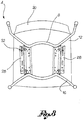
- reference numeral 4 globally denotes a seat element; the seat element may be of any type, such as, for example, a chair, a stool or even an armchair or a sump chair.
- the seat element 4 comprises a frame 8 able to support an associable seat 12 and fitted with at least one means of support 16, such as a foot or a leg.
- the frame 8 is preferably made in metal and is of the tubular type.
- the means of support 16 may be of any type, such as for example a plurality of legs, a central column fitted with arms, with or without castors, and so on.
- the seat 12 may be of various shapes, materials and sizes and may be with or without a backrest 20.
- the frame 8 and the seat 12 are made separately from each other and can be attached and detached from each other, as better described below.
- the frame (8) comprises at least one lateral plate (24), and the seat (12) comprises at least one tab (28) which in an assembled configuration, hooks onto said lateral plate (24) at least partially, in a shaped coupling.
- a snap coupling element (32) is positioned, flexible in relation to the plate (24) and to the tab (28) so as to block the seat (12) to the frame (8) in an assembled configuration of the seat element (4).
- the at least one plate 24 has a snap coupling element 32, flexible in relation to the at least one plate 24 and at least one tab 28, and the tab 28 comprises at least one connection seat 36 able to receive the snap coupling element 32 of the plate 24, so as to block the seat 12 to the frame 8 in an assembled configuration of the seat element4.
- the seat 12 comprises a pair of tabs 28 and the frame 8 comprises a pair of lateral plates 24 which, in an assembled configuration, guide the relative sliding between the seat 12 and the frame 8 in an axial direction X-X essentially parallel to a seat plane 40.
- the lateral plates 24 are positioned to overhang the frame 8, at the lateral extremities 42 of the frame 8.
- the tabs 28 of the seat 12 define cavities 44 with a lower wall 48 of the seat 12 and said cavities 44 house the tabs 28 at least partially, in an assembled configuration of the seat element 4.
- the lateral plates 24 and the cavities 44 are directed in an axial direction X-X, so as to form a prismatic coupling along said axial direction X-X.
- Prismatic coupling is taken to mean a coupling of pure translatory movement which prevents a relative rotation between the two coupled elements.
- the snap coupling element 32 is a spring 52 having an attachment base 56 attached to the frame 8 and a cantilevered flexible arm 60 provided with one free extremity 64 able to snap engage into the connection seats 36 of the tabs 28 of the seat 12.
- the flexible cantilever arm 60 is connected to the attachment base 56 by a connection portion, for example arc-shaped.
- the attachment base 56 is positioned towards the means of support 16, on the side opposite the associable seat 12, so as not to interfere with the seat plane 40.
- the attachment base 56 is attached to the lateral plate 24 of the frame 8 so as not to interfere with the shaped coupling between the lateral plate 24 and the tab 28.
- the flexible cantilever arm 60 is at least partially closed towards the attachment base 56, so that the free extremity 64 of the spring 52 intersects a plane passing through said attachment base 56.
- the plate 24 comprises, at the height of the snap coupling element 32, a through aperture 68 able to allow the passage of said free extremity 64 of the spring 52.
- the free extremity 64 is fitted with a slot portion 72, on the side opposite the attachment base 56, to facilitate the connection of the spring 52 and a front rim 76 of the tabs 28 of the seat 12, during assembly of the seat element 4 in an insertion direction A.
- the free extremity 64, on the side opposite the slot portion 72 has a pawl 80 able to prevent relative withdrawal of the seat 12 from the frame 8 in a withdrawal direction B opposite said insertion direction A.
- the length of the flexible cantilever arm 60 of the spring 52 is such that, in a connection configuration of the free extremity 64 in the connection seat 36, a connection portion 66 between the flexible cantilever arm 60 and the attachment base 56 reaches its final position against a front rim 76 of the tabs 28, so as to form a limit stop to the coupling of the seat 12 and the frame 8.
- the spring 52 is positioned at a rear extremity 84 of the plate 24, on the side opposite the front extremity 88 of the plate 24 suitable for being coupled to a front rim 76 of the tabs 28 of the seat 12; this way the spring 52 prevents reverse assembly of the seat 12 on the side of said rear extremity 84 of the plate 24.
- the spring 52 is preferably of the leaf type with a rectangular cross-section.
- the spring is made from crude steel so as to yield to the tabs 28 and to the plates 24.
- the frame 8 is assembled and the seat 12 brought up to it so as to insert the front extremity 88 of the plates 24 into the cavities 44 delimited by the tabs 28 ( figure 4 ).
- the front rim 76 of the tabs 28 intercepts the free extremity 64 of the spring 52.
- the flexible cantilever arm 60 rises flexibly to allow the sliding of the tabs ( figure 5 ) until the free extremity encounters the connection seat 36 with which it snap couples ( figure 6 ).
- the limit stop occurs contemporarily with the contact between the front rim 76 of the tabs 28 and the connection portion 66 of the spring 52.
- a screwdriver may be used for this purpose, inserting the tip between the flexible cantilever arm 60 of the spring 52 and the tab 28 of the seat 12.
- the seat element according to the invention makes it possible to overcome the drawbacks spoken of in relation to the prior art.
- the seat element is particularly practical and easy to assemble and dismantle.
- the coupling and detachment element does not cause any abrasion of the seat or seat covering where present.
- the coupling element is sturdy and does not break even if the assembly and dismantling phase is performed repeatedly.
- the coupling element is small and practically invisible in conditions of normal use of the seat element.
- the cost of producing and assembling the coupling element is extremely limited and does not substantially influence the overall cost of the seat element.
Landscapes
- Chairs For Special Purposes, Such As Reclining Chairs (AREA)
- Seats For Vehicles (AREA)
Claims (15)
- Elément de siège (4) comprenant- un cadre (8) adapté pour supporter un siège (12) pouvant être associé et pourvu d'au moins un moyen de support (16) tel un pied ou une jambe,- un siège (12) pouvant être associé au cadre (8),- le cadre (8) et le siège (12) étant réalisés séparément l'un de l'autre et étant adaptés pour être attachés l'un à l'autre ou détachés l'un de l'autre à l'aide d'un élément d'assemblage à enclenchement (32),caractérisé en ce que- le cadre (8) comprend au moins une plaque latérale (24),- le siège (12) comprend au moins une équerre (28) qui, en configuration assemblée, s'accroche sur la plaque latérale (24) au moins partiellement dans un accouplement conformé, où- entre ladite au moins une équerre (28) et ladite au moins une plaque (24), l'élément d'assemblage à enclenchement (32) est positionné, de façon flexible par rapport à la plaque (24) et à l'équerre (28), de façon à bloquer le siège (12) au cadre (8) dans une configuration assemblée de l'élément de siège (4).
- Elément de siège (4) selon la revendication 1, caractérisé en ce que ladite au moins une plaque (24) comprend un élément d'assemblage à enclenchement (32), flexible par rapport à ladite au moins une plaque (24) et ladite au moins une équerre (28), et l'équerre (28) comprenant au moins un siège de connexion (36) étant apte à recevoir l'élément d'assemblage à enclenchement (32) de la plaque (24) afin de bloquer le siège (12) au cadre (8) dans une configuration assemblée de l'élément de siège (4).
- Elément de siège (4) selon la revendication 1 ou 2, caractérisé en ce que le siège (12) comprend une paire d'équerres (28) et le cadre (8) comprend une paire de plaques latérales (24) qui, dans une configuration assemblée, guide le coulissement relatif entre le siège (12) et le cadre (8) dans une direction axiale (X-X) sensiblement parallèle au plan de siège (40).
- Elément de siège (4) selon la revendication 1, 2 ou 3, caractérisé en ce que les équerres (28) du siège (12) définissent des cavités (44) avec une paroi inférieure (48) du siège (12) et les cavités (44) logent les équerres (28) au moins partiellement dans une configuration assemblée de l'élément de siège (4).
- Elément de siège (4) selon l'une des revendications précédentes, caractérisé en ce que les plaques latérales (24) et les cavités (44) sont orientées dans une direction axiale (X-X) afin de former un accouplement prismatique le long de cette direction axiale (X-X).
- Elément de siège (4) selon l'une des revendications précédentes, caractérisé en ce que les plaques latérales (24) sont positionnées de façon dépasser du cadre (8) aux extrémités latérales (42) du cadre (8).
- Elément de siège (4) selon l'une des revendications précédentes, caractérisé en ce que l'élément d'assemblage à enclenchement (32) est un ressort (52) ayant une base d'assemblage (56) attachée au cadre (8) et un bras flexible en porte-à-faux (60) pourvu d'une extrémité libre (64) adaptée pour s'engager par enclenchement dans les sièges de connexion (36) des équerres (28) du siège (12).
- Elément de siège (4) selon la revendication 7, caractérisé en ce que la base d'assemblage (56) est positionnée vers les moyens de support (16), du côté opposé au siège (12) pouvant être associé, afin de ne pas interférer avec le plan de siège (40).
- Elément de siège (4) selon la revendication 7 ou 8, caractérisé en ce que, dans une condition libre, le bras flexible en porte-à-faux (60) est au moins partiellement fermé vers la base d'assemblage (56) afin que l'extrémité libre (64) du ressort (52) coupe un plan passant par la base d'assemblage (56).
- Elément de siège (4) selon l'une des revendications précédentes de 7 à 9, caractérisé en ce que la plaque (24) comprend, à hauteur de l'élément d'assemblage à enclenchement (32), un trou de passage (68) adapté pour laisser passer l'extrémité libre (64) du ressort (52).
- Elément de siège (4) selon l'une des revendications précédentes de 7 à 10, caractérisé en ce que l'extrémité libre (64) est pourvue, du côté opposé à la base d'assemblage (56), d'une partie à fente (72) pour faciliter la connexion du ressort (52) et d'un rebord avant (76) de l'équerre (28) du siège (12) pendant l'assemblage de l'élément de siège (4) dans une direction d'insertion (A).
- Elément de siège (4) selon la revendication 11, caractérisé en ce que l'extrémité libre (64) en face de la partie à fente (72) comporte un cliquet (80) apte à éviter un retrait relatif du siège (12) du cadre (8) dans une direction de retrait (B) opposée à la direction d'insertion (A).
- Elément de siège (4) selon l'une des revendications précédentes de 7 à 12, caractérisé en ce que la longueur du bras flexible en porte-à-faux (60) du ressort (52) est telle que, dans une configuration de connexion de l'extrémité libre (64) dans le siège de connexion (36), une partie de connexion (66) entre le bras flexible en porte-à-faux (60) et la base d'assemblage (56) atteigne sa position finale contre un rebord avant (76) des équerres (28), afin de former une limite d'arrêt à l'accouplement du siège (12) et du cadre (8).
- Elément de siège (4) selon l'une des revendications précédentes de 7 à 13, caractérisé en ce que le ressort (52) est positionné à une extrémité arrière (84) de la plaque (24), du côté opposé à l'extrémité avant (88) de la plaque (24), de façon appropriée pour être accouplé au rebord avant (76) des équerres (28) du siège (12), le ressort (52) évitant un assemblage à l'envers du siège (12) du côté de l'extrémité arrière (84) de la plaque (24).
- Elément de siège (4) selon l'une des revendications précédentes de 7 à 13, caractérisé en ce que le ressort (52) est fait en acier brut afin de céder aux équerres (28) et aux plaques (24).
Priority Applications (1)
| Application Number | Priority Date | Filing Date | Title |
|---|---|---|---|
| PL10752408T PL2473079T3 (pl) | 2009-09-03 | 2010-08-06 | Siedziskowy element |
Applications Claiming Priority (2)
| Application Number | Priority Date | Filing Date | Title |
|---|---|---|---|
| ITPD2009A000250A IT1395525B1 (it) | 2009-09-03 | 2009-09-03 | Elemento di seduta |
| PCT/IB2010/053571 WO2011027245A1 (fr) | 2009-09-03 | 2010-08-06 | Élément de siège |
Publications (2)
| Publication Number | Publication Date |
|---|---|
| EP2473079A1 EP2473079A1 (fr) | 2012-07-11 |
| EP2473079B1 true EP2473079B1 (fr) | 2017-09-20 |
Family
ID=42062310
Family Applications (1)
| Application Number | Title | Priority Date | Filing Date |
|---|---|---|---|
| EP10752408.4A Active EP2473079B1 (fr) | 2009-09-03 | 2010-08-06 | Élément de siège |
Country Status (11)
| Country | Link |
|---|---|
| US (1) | US8857912B2 (fr) |
| EP (1) | EP2473079B1 (fr) |
| JP (1) | JP2013503678A (fr) |
| CA (1) | CA2759504C (fr) |
| DK (1) | DK2473079T3 (fr) |
| ES (1) | ES2653565T3 (fr) |
| IT (1) | IT1395525B1 (fr) |
| NO (1) | NO2473079T3 (fr) |
| PL (1) | PL2473079T3 (fr) |
| SG (1) | SG175357A1 (fr) |
| WO (1) | WO2011027245A1 (fr) |
Families Citing this family (7)
| Publication number | Priority date | Publication date | Assignee | Title |
|---|---|---|---|---|
| US9027996B2 (en) * | 2012-05-21 | 2015-05-12 | Wonderland Nurserygoods Company Limited | Safety seat |
| USD745787S1 (en) * | 2014-08-21 | 2015-12-22 | Kien C. Tiet | Chair |
| USD740584S1 (en) * | 2014-08-21 | 2015-10-13 | Kien C. Tiet | Chair |
| DE202018100290U1 (de) * | 2018-01-18 | 2018-03-23 | Veba Event Products | Kupplungsmechanismus für einen Stuhl mit lösbarem Sitz |
| USD887151S1 (en) * | 2018-06-05 | 2020-06-16 | Allseating Corporation | Chair |
| SE543531C2 (en) * | 2018-10-01 | 2021-03-23 | Ikea Supply Ag | Seat clip, chair comprising seat clip and method for assembling a chair |
| CN218683097U (zh) * | 2022-09-28 | 2023-03-24 | 圣奥科技股份有限公司 | 一种座椅底盘与座垫快装结构 |
Family Cites Families (15)
| Publication number | Priority date | Publication date | Assignee | Title |
|---|---|---|---|---|
| US1232931A (en) * | 1912-12-06 | 1917-07-10 | Hale & Kilburn Co | Car-seat. |
| US4169627A (en) * | 1978-07-31 | 1979-10-02 | Lear Siegler, Inc. | Frame retention system for seat components |
| US4395071A (en) * | 1981-02-23 | 1983-07-26 | Laird William B | Furniture with removable cushions |
| US4488755A (en) * | 1982-09-20 | 1984-12-18 | Nemschoff Chairs, Inc. | Chair with reversible seat and back cushions |
| US5064247A (en) * | 1990-05-23 | 1991-11-12 | Allsteel Inc. | Wire rod office furniture stacking chair |
| US6543842B2 (en) * | 2000-02-03 | 2003-04-08 | Lifetime Products, Inc. | Interference fit support bracket for a portable folding chair |
| US6637823B1 (en) * | 2000-10-17 | 2003-10-28 | Majestic Industries, Inc. | Chair with removable cushion and back sections and method for practice same |
| SM200100015A (it) * | 2001-08-09 | 2003-02-12 | Arper Spa | Struttura di sedia |
| US6698840B1 (en) * | 2002-08-12 | 2004-03-02 | Shin Yeh Enterprise Co., Ltd. | Chair with a detachable backrest |
| US7226130B2 (en) * | 2002-09-12 | 2007-06-05 | Steelcase Development Corporation | Seating with comfort surface |
| US20050151409A1 (en) * | 2004-01-09 | 2005-07-14 | Vittorio Infanti | Chair with readily removable and replaceable components |
| US20060273642A1 (en) * | 2005-06-03 | 2006-12-07 | Sunpex Technology Co., Ltd. | Motor-driven vehicle with a removable seat |
| JP2007038852A (ja) * | 2005-08-03 | 2007-02-15 | Aisin Seiki Co Ltd | 車両用シート装置 |
| ITMI20070943A1 (it) * | 2007-05-09 | 2008-11-10 | L & P Property Management Co | Sedile per sedie o poltrone particolarmente di tipo regolabile per ufficio. |
| US7909407B2 (en) * | 2007-06-07 | 2011-03-22 | Lear Corporation | Vehicle seat connection |
-
2009
- 2009-09-03 IT ITPD2009A000250A patent/IT1395525B1/it active
-
2010
- 2010-08-06 DK DK10752408.4T patent/DK2473079T3/en active
- 2010-08-06 JP JP2012527413A patent/JP2013503678A/ja active Pending
- 2010-08-06 NO NO10752408A patent/NO2473079T3/no unknown
- 2010-08-06 SG SG2011078557A patent/SG175357A1/en unknown
- 2010-08-06 US US13/266,170 patent/US8857912B2/en active Active
- 2010-08-06 PL PL10752408T patent/PL2473079T3/pl unknown
- 2010-08-06 ES ES10752408.4T patent/ES2653565T3/es active Active
- 2010-08-06 CA CA2759504A patent/CA2759504C/fr active Active
- 2010-08-06 WO PCT/IB2010/053571 patent/WO2011027245A1/fr not_active Ceased
- 2010-08-06 EP EP10752408.4A patent/EP2473079B1/fr active Active
Non-Patent Citations (1)
| Title |
|---|
| None * |
Also Published As
| Publication number | Publication date |
|---|---|
| JP2013503678A (ja) | 2013-02-04 |
| NO2473079T3 (fr) | 2018-02-17 |
| ES2653565T3 (es) | 2018-02-07 |
| PL2473079T3 (pl) | 2018-03-30 |
| CA2759504C (fr) | 2017-07-18 |
| WO2011027245A1 (fr) | 2011-03-10 |
| US8857912B2 (en) | 2014-10-14 |
| SG175357A1 (en) | 2011-11-28 |
| EP2473079A1 (fr) | 2012-07-11 |
| ITPD20090250A1 (it) | 2011-03-04 |
| US20120038198A1 (en) | 2012-02-16 |
| CA2759504A1 (fr) | 2011-03-10 |
| DK2473079T3 (en) | 2018-01-08 |
| IT1395525B1 (it) | 2012-09-28 |
Similar Documents
| Publication | Publication Date | Title |
|---|---|---|
| EP2473079B1 (fr) | Élément de siège | |
| EP2421406B2 (fr) | Système de prévention de relâchement pour armoires murales | |
| EP2517606B1 (fr) | Une chaise avec dossier basculant | |
| JP6382501B2 (ja) | 椅子 | |
| US8882201B2 (en) | Seat element | |
| CN217039456U (zh) | 一种组合式家具 | |
| JP2017113465A (ja) | 椅子の背もたれ | |
| JP6485946B2 (ja) | 椅子 | |
| JP5224271B2 (ja) | 椅子 | |
| EP1042976A1 (fr) | Siège ou similaire avec procédé d'assemblage facilité | |
| JP6279883B2 (ja) | 椅子における表装部材の取付構造 | |
| CN215216514U (zh) | 冷风扇 | |
| US20100176643A1 (en) | Universal Arm Assembly Connection For Furniture Members | |
| KR20090060464A (ko) | 욕실용품 지지대 체결구 | |
| JP6367536B2 (ja) | 椅子 | |
| WO2025153967A1 (fr) | Kit de canapé, fauteuil ou meuble analogue, et procédé d'assemblage associé | |
| CN220898299U (zh) | 一种坐具支撑结构及坐具 | |
| JP3063321U (ja) | スライドレ―ル | |
| KR200428390Y1 (ko) | 의자좌석 | |
| KR200434667Y1 (ko) | 소파 겸용 침대 프레임 | |
| KR100666507B1 (ko) | 높이 조절장치 | |
| JP6608248B2 (ja) | 椅子 | |
| JP6464033B2 (ja) | 椅子のメモ台取付け構造並びにそれを用いた椅子 | |
| KR200432196Y1 (ko) | 의자용 등판의 각도조절구 | |
| KR20200001381A (ko) | 스페이서를 구비한 걸고리형 수납식 관람석 |
Legal Events
| Date | Code | Title | Description |
|---|---|---|---|
| PUAI | Public reference made under article 153(3) epc to a published international application that has entered the european phase |
Free format text: ORIGINAL CODE: 0009012 |
|
| 17P | Request for examination filed |
Effective date: 20111019 |
|
| AK | Designated contracting states |
Kind code of ref document: A1 Designated state(s): AL AT BE BG CH CY CZ DE DK EE ES FI FR GB GR HR HU IE IS IT LI LT LU LV MC MK MT NL NO PL PT RO SE SI SK SM TR |
|
| DAX | Request for extension of the european patent (deleted) | ||
| 17Q | First examination report despatched |
Effective date: 20141222 |
|
| GRAP | Despatch of communication of intention to grant a patent |
Free format text: ORIGINAL CODE: EPIDOSNIGR1 |
|
| RAP1 | Party data changed (applicant data changed or rights of an application transferred) |
Owner name: ARPER S.P.A. |
|
| INTG | Intention to grant announced |
Effective date: 20170406 |
|
| GRAS | Grant fee paid |
Free format text: ORIGINAL CODE: EPIDOSNIGR3 |
|
| GRAA | (expected) grant |
Free format text: ORIGINAL CODE: 0009210 |
|
| AK | Designated contracting states |
Kind code of ref document: B1 Designated state(s): AL AT BE BG CH CY CZ DE DK EE ES FI FR GB GR HR HU IE IS IT LI LT LU LV MC MK MT NL NO PL PT RO SE SI SK SM TR |
|
| REG | Reference to a national code |
Ref country code: GB Ref legal event code: FG4D |
|
| REG | Reference to a national code |
Ref country code: CH Ref legal event code: EP |
|
| REG | Reference to a national code |
Ref country code: AT Ref legal event code: REF Ref document number: 929475 Country of ref document: AT Kind code of ref document: T Effective date: 20171015 |
|
| REG | Reference to a national code |
Ref country code: IE Ref legal event code: FG4D |
|
| REG | Reference to a national code |
Ref country code: DE Ref legal event code: R096 Ref document number: 602010045378 Country of ref document: DE |
|
| REG | Reference to a national code |
Ref country code: DK Ref legal event code: T3 Effective date: 20180105 |
|
| REG | Reference to a national code |
Ref country code: SE Ref legal event code: TRGR |
|
| REG | Reference to a national code |
Ref country code: NL Ref legal event code: FP |
|
| PG25 | Lapsed in a contracting state [announced via postgrant information from national office to epo] |
Ref country code: FI Free format text: LAPSE BECAUSE OF FAILURE TO SUBMIT A TRANSLATION OF THE DESCRIPTION OR TO PAY THE FEE WITHIN THE PRESCRIBED TIME-LIMIT Effective date: 20170920 Ref country code: LT Free format text: LAPSE BECAUSE OF FAILURE TO SUBMIT A TRANSLATION OF THE DESCRIPTION OR TO PAY THE FEE WITHIN THE PRESCRIBED TIME-LIMIT Effective date: 20170920 Ref country code: HR Free format text: LAPSE BECAUSE OF FAILURE TO SUBMIT A TRANSLATION OF THE DESCRIPTION OR TO PAY THE FEE WITHIN THE PRESCRIBED TIME-LIMIT Effective date: 20170920 |
|
| REG | Reference to a national code |
Ref country code: ES Ref legal event code: FG2A Ref document number: 2653565 Country of ref document: ES Kind code of ref document: T3 Effective date: 20180207 |
|
| REG | Reference to a national code |
Ref country code: LT Ref legal event code: MG4D |
|
| REG | Reference to a national code |
Ref country code: NO Ref legal event code: T2 Effective date: 20170920 |
|
| PG25 | Lapsed in a contracting state [announced via postgrant information from national office to epo] |
Ref country code: GR Free format text: LAPSE BECAUSE OF FAILURE TO SUBMIT A TRANSLATION OF THE DESCRIPTION OR TO PAY THE FEE WITHIN THE PRESCRIBED TIME-LIMIT Effective date: 20171221 Ref country code: BG Free format text: LAPSE BECAUSE OF FAILURE TO SUBMIT A TRANSLATION OF THE DESCRIPTION OR TO PAY THE FEE WITHIN THE PRESCRIBED TIME-LIMIT Effective date: 20171220 Ref country code: LV Free format text: LAPSE BECAUSE OF FAILURE TO SUBMIT A TRANSLATION OF THE DESCRIPTION OR TO PAY THE FEE WITHIN THE PRESCRIBED TIME-LIMIT Effective date: 20170920 |
|
| PG25 | Lapsed in a contracting state [announced via postgrant information from national office to epo] |
Ref country code: RO Free format text: LAPSE BECAUSE OF FAILURE TO SUBMIT A TRANSLATION OF THE DESCRIPTION OR TO PAY THE FEE WITHIN THE PRESCRIBED TIME-LIMIT Effective date: 20170920 Ref country code: CZ Free format text: LAPSE BECAUSE OF FAILURE TO SUBMIT A TRANSLATION OF THE DESCRIPTION OR TO PAY THE FEE WITHIN THE PRESCRIBED TIME-LIMIT Effective date: 20170920 |
|
| PG25 | Lapsed in a contracting state [announced via postgrant information from national office to epo] |
Ref country code: PT Free format text: LAPSE BECAUSE OF FAILURE TO SUBMIT A TRANSLATION OF THE DESCRIPTION OR TO PAY THE FEE WITHIN THE PRESCRIBED TIME-LIMIT Effective date: 20180122 Ref country code: IS Free format text: LAPSE BECAUSE OF FAILURE TO SUBMIT A TRANSLATION OF THE DESCRIPTION OR TO PAY THE FEE WITHIN THE PRESCRIBED TIME-LIMIT Effective date: 20180120 Ref country code: SK Free format text: LAPSE BECAUSE OF FAILURE TO SUBMIT A TRANSLATION OF THE DESCRIPTION OR TO PAY THE FEE WITHIN THE PRESCRIBED TIME-LIMIT Effective date: 20170920 Ref country code: EE Free format text: LAPSE BECAUSE OF FAILURE TO SUBMIT A TRANSLATION OF THE DESCRIPTION OR TO PAY THE FEE WITHIN THE PRESCRIBED TIME-LIMIT Effective date: 20170920 Ref country code: SM Free format text: LAPSE BECAUSE OF FAILURE TO SUBMIT A TRANSLATION OF THE DESCRIPTION OR TO PAY THE FEE WITHIN THE PRESCRIBED TIME-LIMIT Effective date: 20170920 |
|
| REG | Reference to a national code |
Ref country code: DE Ref legal event code: R097 Ref document number: 602010045378 Country of ref document: DE |
|
| PLBE | No opposition filed within time limit |
Free format text: ORIGINAL CODE: 0009261 |
|
| STAA | Information on the status of an ep patent application or granted ep patent |
Free format text: STATUS: NO OPPOSITION FILED WITHIN TIME LIMIT |
|
| 26N | No opposition filed |
Effective date: 20180621 |
|
| REG | Reference to a national code |
Ref country code: FR Ref legal event code: PLFP Year of fee payment: 9 |
|
| PG25 | Lapsed in a contracting state [announced via postgrant information from national office to epo] |
Ref country code: SI Free format text: LAPSE BECAUSE OF FAILURE TO SUBMIT A TRANSLATION OF THE DESCRIPTION OR TO PAY THE FEE WITHIN THE PRESCRIBED TIME-LIMIT Effective date: 20170920 |
|
| PG25 | Lapsed in a contracting state [announced via postgrant information from national office to epo] |
Ref country code: MC Free format text: LAPSE BECAUSE OF FAILURE TO SUBMIT A TRANSLATION OF THE DESCRIPTION OR TO PAY THE FEE WITHIN THE PRESCRIBED TIME-LIMIT Effective date: 20170920 |
|
| REG | Reference to a national code |
Ref country code: CH Ref legal event code: PL |
|
| PG25 | Lapsed in a contracting state [announced via postgrant information from national office to epo] |
Ref country code: LI Free format text: LAPSE BECAUSE OF NON-PAYMENT OF DUE FEES Effective date: 20180831 Ref country code: LU Free format text: LAPSE BECAUSE OF NON-PAYMENT OF DUE FEES Effective date: 20180806 Ref country code: CH Free format text: LAPSE BECAUSE OF NON-PAYMENT OF DUE FEES Effective date: 20180831 |
|
| REG | Reference to a national code |
Ref country code: IE Ref legal event code: MM4A |
|
| PG25 | Lapsed in a contracting state [announced via postgrant information from national office to epo] |
Ref country code: IE Free format text: LAPSE BECAUSE OF NON-PAYMENT OF DUE FEES Effective date: 20180806 |
|
| PG25 | Lapsed in a contracting state [announced via postgrant information from national office to epo] |
Ref country code: MT Free format text: LAPSE BECAUSE OF NON-PAYMENT OF DUE FEES Effective date: 20180806 |
|
| REG | Reference to a national code |
Ref country code: AT Ref legal event code: UEP Ref document number: 929475 Country of ref document: AT Kind code of ref document: T Effective date: 20170920 |
|
| PG25 | Lapsed in a contracting state [announced via postgrant information from national office to epo] |
Ref country code: HU Free format text: LAPSE BECAUSE OF FAILURE TO SUBMIT A TRANSLATION OF THE DESCRIPTION OR TO PAY THE FEE WITHIN THE PRESCRIBED TIME-LIMIT; INVALID AB INITIO Effective date: 20100806 |
|
| PG25 | Lapsed in a contracting state [announced via postgrant information from national office to epo] |
Ref country code: CY Free format text: LAPSE BECAUSE OF FAILURE TO SUBMIT A TRANSLATION OF THE DESCRIPTION OR TO PAY THE FEE WITHIN THE PRESCRIBED TIME-LIMIT Effective date: 20170920 Ref country code: MK Free format text: LAPSE BECAUSE OF NON-PAYMENT OF DUE FEES Effective date: 20170920 |
|
| PG25 | Lapsed in a contracting state [announced via postgrant information from national office to epo] |
Ref country code: AL Free format text: LAPSE BECAUSE OF FAILURE TO SUBMIT A TRANSLATION OF THE DESCRIPTION OR TO PAY THE FEE WITHIN THE PRESCRIBED TIME-LIMIT Effective date: 20170920 |
|
| PGFP | Annual fee paid to national office [announced via postgrant information from national office to epo] |
Ref country code: NL Payment date: 20240826 Year of fee payment: 15 |
|
| PGFP | Annual fee paid to national office [announced via postgrant information from national office to epo] |
Ref country code: DE Payment date: 20240812 Year of fee payment: 15 |
|
| PGFP | Annual fee paid to national office [announced via postgrant information from national office to epo] |
Ref country code: DK Payment date: 20240829 Year of fee payment: 15 |
|
| PGFP | Annual fee paid to national office [announced via postgrant information from national office to epo] |
Ref country code: GB Payment date: 20240826 Year of fee payment: 15 |
|
| PGFP | Annual fee paid to national office [announced via postgrant information from national office to epo] |
Ref country code: BE Payment date: 20240821 Year of fee payment: 15 |
|
| PGFP | Annual fee paid to national office [announced via postgrant information from national office to epo] |
Ref country code: FR Payment date: 20240730 Year of fee payment: 15 |
|
| PGFP | Annual fee paid to national office [announced via postgrant information from national office to epo] |
Ref country code: AT Payment date: 20240820 Year of fee payment: 15 |
|
| PGFP | Annual fee paid to national office [announced via postgrant information from national office to epo] |
Ref country code: NO Payment date: 20240819 Year of fee payment: 15 Ref country code: SE Payment date: 20240820 Year of fee payment: 15 |
|
| PGFP | Annual fee paid to national office [announced via postgrant information from national office to epo] |
Ref country code: ES Payment date: 20250901 Year of fee payment: 16 |
|
| PGFP | Annual fee paid to national office [announced via postgrant information from national office to epo] |
Ref country code: TR Payment date: 20250803 Year of fee payment: 16 Ref country code: PL Payment date: 20250725 Year of fee payment: 16 Ref country code: IT Payment date: 20250624 Year of fee payment: 16 |
|
| REG | Reference to a national code |
Ref country code: DE Ref legal event code: R119 Ref document number: 602010045378 Country of ref document: DE |
|
| REG | Reference to a national code |
Ref country code: DK Ref legal event code: EBP Effective date: 20250831 |
|
| REG | Reference to a national code |
Ref country code: NL Ref legal event code: MM Effective date: 20250901 |
|
| PG25 | Lapsed in a contracting state [announced via postgrant information from national office to epo] |
Ref country code: NO Free format text: LAPSE BECAUSE OF NON-PAYMENT OF DUE FEES Effective date: 20250831 |
|
| PG25 | Lapsed in a contracting state [announced via postgrant information from national office to epo] |
Ref country code: AT Free format text: LAPSE BECAUSE OF NON-PAYMENT OF DUE FEES Effective date: 20250806 |
|
| REG | Reference to a national code |
Ref country code: AT Ref legal event code: MM01 Ref document number: 929475 Country of ref document: AT Kind code of ref document: T Effective date: 20250806 |