EP2473418B1 - Behälterverschlussanordnung - Google Patents
Behälterverschlussanordnung Download PDFInfo
- Publication number
- EP2473418B1 EP2473418B1 EP10752539.6A EP10752539A EP2473418B1 EP 2473418 B1 EP2473418 B1 EP 2473418B1 EP 10752539 A EP10752539 A EP 10752539A EP 2473418 B1 EP2473418 B1 EP 2473418B1
- Authority
- EP
- European Patent Office
- Prior art keywords
- container
- reservoir
- neck
- closure cap
- wall
- Prior art date
- Legal status (The legal status is an assumption and is not a legal conclusion. Google has not performed a legal analysis and makes no representation as to the accuracy of the status listed.)
- Not-in-force
Links
Images


Classifications
-
- B—PERFORMING OPERATIONS; TRANSPORTING
- B65—CONVEYING; PACKING; STORING; HANDLING THIN OR FILAMENTARY MATERIAL
- B65D—CONTAINERS FOR STORAGE OR TRANSPORT OF ARTICLES OR MATERIALS, e.g. BAGS, BARRELS, BOTTLES, BOXES, CANS, CARTONS, CRATES, DRUMS, JARS, TANKS, HOPPERS, FORWARDING CONTAINERS; ACCESSORIES, CLOSURES, OR FITTINGS THEREFOR; PACKAGING ELEMENTS; PACKAGES
- B65D51/00—Closures not otherwise provided for
- B65D51/24—Closures not otherwise provided for combined or co-operating with auxiliary devices for non-closing purposes
- B65D51/28—Closures not otherwise provided for combined or co-operating with auxiliary devices for non-closing purposes with auxiliary containers for additional articles or materials
- B65D51/2807—Closures not otherwise provided for combined or co-operating with auxiliary devices for non-closing purposes with auxiliary containers for additional articles or materials the closure presenting means for placing the additional articles or materials in contact with the main contents by acting on a part of the closure without removing the closure, e.g. by pushing down, pulling up, rotating or turning a part of the closure, or upon initial opening of the container
-
- B—PERFORMING OPERATIONS; TRANSPORTING
- B65—CONVEYING; PACKING; STORING; HANDLING THIN OR FILAMENTARY MATERIAL
- B65D—CONTAINERS FOR STORAGE OR TRANSPORT OF ARTICLES OR MATERIALS, e.g. BAGS, BARRELS, BOTTLES, BOXES, CANS, CARTONS, CRATES, DRUMS, JARS, TANKS, HOPPERS, FORWARDING CONTAINERS; ACCESSORIES, CLOSURES, OR FITTINGS THEREFOR; PACKAGING ELEMENTS; PACKAGES
- B65D51/00—Closures not otherwise provided for
- B65D51/24—Closures not otherwise provided for combined or co-operating with auxiliary devices for non-closing purposes
- B65D51/28—Closures not otherwise provided for combined or co-operating with auxiliary devices for non-closing purposes with auxiliary containers for additional articles or materials
- B65D51/2807—Closures not otherwise provided for combined or co-operating with auxiliary devices for non-closing purposes with auxiliary containers for additional articles or materials the closure presenting means for placing the additional articles or materials in contact with the main contents by acting on a part of the closure without removing the closure, e.g. by pushing down, pulling up, rotating or turning a part of the closure, or upon initial opening of the container
- B65D51/2857—Closures not otherwise provided for combined or co-operating with auxiliary devices for non-closing purposes with auxiliary containers for additional articles or materials the closure presenting means for placing the additional articles or materials in contact with the main contents by acting on a part of the closure without removing the closure, e.g. by pushing down, pulling up, rotating or turning a part of the closure, or upon initial opening of the container the additional article or materials being released by displacing or removing an element enclosing it
- B65D51/2892—Closures not otherwise provided for combined or co-operating with auxiliary devices for non-closing purposes with auxiliary containers for additional articles or materials the closure presenting means for placing the additional articles or materials in contact with the main contents by acting on a part of the closure without removing the closure, e.g. by pushing down, pulling up, rotating or turning a part of the closure, or upon initial opening of the container the additional article or materials being released by displacing or removing an element enclosing it the element, e.g. a valve, opening an aperture of the auxiliary container
Definitions
- the invention relates to container closure assemblies incorporating a reservoir for material (typically a liquid, a powder or a granulate material) which is kept separate from the material (typically liquid) in the container until mixing of the materials is required.
- material typically a liquid, a powder or a granulate material
- a generally cylindrical reservoir for liquid is screw threaded into an annular end piece fitted irremovably to the neck of a container.
- a closure member is dislodged from the reservoir and drops into the container allowing liquid in the reservoir to be dispensed through the end piece into the container.
- the mixed liquids can be poured through the end piece.
- US 2004/0200741 discloses a cap device for bottles, in which a valve means is stably placed at a desired position in a neck of a bottle, which allows an additive to be stored completely separated in the cap device.
- the cap device has a funnel part integrally formed in the cap body to discharge the additive from the cap body into the bottle through a lower end thereof.
- DE 29820062 concerns a closure cap with an additional container, the container having a bottom wall which is connected to the sidewall by a predetermined breaking line.
- the closure cap further comprises a cylindrically formed pusher, such that the container is opened when the pusher moves axially towards the container bottom.
- EP 1 477 421 concerns a closure cap comprising a cylindrical wall projecting axially from the top wall and forming a receiving chamber.
- the receiving chamber has an opening at its lower end.
- a seal plug is removably attachable to the cylindrical wall to close the chamber.
- a sleeve with a protruding portion is arranged to be fixed to the opening portion of the vessel.
- the seal plug is only allowed to pass the protruding portion in direction of insertion but not in direction of removal. Thus the plug remains underneath the protruding portion when the closures cap is removed from the vessel and the receiving chamber is opened.
- the plug is not fixed with respect to the container after opening and hence is free to move. The plug may thus block the opening when the content shall be removed from the container.
- EP 1 919 791 shows a closure cap adapted to be fitted to the neck of a container to close the container comprising an upper wall and a cylindrical skirt depending therefrom and having a reservoir formed on the underside of the upper wall within the skirt.
- the reservoir is provided with a dispensing opening.
- a sealing member is adapted to be fitted into the closure cap to close the dispensing opening in the reservoir.
- the sealing member is also adapted to fit into the neck of the container, when the assembly is fitted thereto, with an interference fit such that when the closure cap is removed from the container, the sealing member remains held within the neck of the container and is separated from the closure cap so that the dispensing opening is opened and material contained therein is dispensed into the container.
- the sealing member extends to the upper edge of the container neck.
- a second cylindrical wall extends downwardly from the underside of the closure cap radially outwardly of the reservoir and fits sealingly into the upper end of the sealing member.
- the invention provides a closure assembly according to claim 1 with closure cap adapted to be fitted to the neck of a container to close the container and comprising an upper wall and a cylindrical skirt depending therefrom.
- a reservoir is formed on the underside of the upper wall within the skirt and is provided with a dispensing opening and a closing member to close the dispensing opening of the reservoir.
- the closing member comprises a fixing member, a plug member and a passage element.
- the fixing member is adapted to fit into the neck of the container, when the assembly is fitted thereto, with an interference fit such that when the closure cap is removed from the container, the closing member remains held within the neck of the container.
- the plug member is adapted to sealingly fit into an open end of the reservoir to close the reservoir when the closure cap and the closing member are fitted together.
- the passage element allows material to be dispenses from the reservoir into the container when the closure cap is removed from the container neck and the closing member is separated from the closure cap.
- the closing member remains in the container neck as a whole. The seal between plug member and reservoir is broken and material is dispensed from the reservoir into the container through the passage element.
- the closure cap is provided with separate sealing means such as sealing lips or a sealing liner for directly sealing against the container neck.
- sealing means such as sealing lips or a sealing liner for directly sealing against the container neck.
- an annual wall extends downwardly from the underside of the upper wall of the closure cap to fit sealingly into the neck of the container.
- An upper end of the fixing member rests below the upper rim of the container neck.
- the arrangement allows for the reservoir to be filled and the sealing member to be fitted to the closure cap to form an assembly which can be freely transported and handled by standard machinery set up to handle a plain container closure consisting simply of an end wall and a depending skirt.
- the annular wall can directly seal against the inner surface of a container neck.
- an approved standard sealing lip can be used.
- a first sealing between the reservoir and the closing member is formed by the plug element of the closing member which seals the reservoir.
- a second sealing between the closure cap and the container neck is formed by a standard sealing means forming a seal between the closure cap and the container neck, such as an annular wall.
- the fixation of the closing member in the container will stay intact when the closure cap is removed from the bottle and the content of the reservoir will be dispensed into the container.
- the fixing member is arranged axially below the annular wall, when the assembly is fitted to the container.
- the fixing member and the annular wall are both adapted to fit into the neck of the container, thus the upper section of the container neck is occupied by the annular wall, whereas the sealing member is arranged in the lower section and has an axial distance from the upper end of the container neck.
- the annular wall comprises a closure sealing zone, in which the outer diameter of the annular wall is greater than the inner diameter of the container neck.
- This region provides a reliable sealing between closure cap and container as long as the closure cap is fitted to the container.
- Such seals typically are known as olive seals.
- the fixing member comprises at least one fixation zone, in which the outer diameter of the sealing member is greater than the inner diameter of the container neck, more preferably there are two or three fixation zones in an axial distance form another.
- the fixation zones support a reliable contact between the fixing member and the container neck and support for the closing member remaining in the container neck when the closure cap is removed.
- the reservoir is formed by an annular reservoir wall, more preferably a cylindrical wall, extending downwardly from the underside of the upper wall of the closure cap.
- the closure cap may be easily completely deformed from a mould while at the same time offering enough volume inside the reservoir.
- the reservoir may also be formed by a downwardly extending wall which is slightly conical.
- the reservoir wall provides at his end an undercut which snaps with the closing member, preventing therefore that said closing member falls out accidentally during handling or transportation.
- the passage element may be furnished with windows. As long as the closure cap is applied to the container neck and as long as it is in the closing position the reservoir is closed by the plug member and the content of the reservoir may not pour through the windows.
- the passage element comprises a plurality of radial bridges and passages are formed between the radial bridges such that when the closure cap is separated from the container neck and the closing member, material can be dispensed from the reservoir through the passages and into the container.
- the bridges form a connection between the plug element and the fixing element.
- the axial length of the reservoir corresponds approximately to the sum of the axial length of the fixing member and the axial length of the annular wall.
- the axial length of the fixing member is longer than the axial length of the annular wall, since the closure cap has to be removed from the container neck for opening and the closing member is meant to remain inside the container neck and thus needs a sufficient contact area.
- closure cap may comprise at least one centring member extending downwardly from the underside of the upper wall radially outwardly of the reservoir and radially inwardly of the annular wall, preferably arranged on the outer surface of the wall defining the reservoir.
- the centring members help to adjust the fixing members with respect to the container neck when the closure cap is applied to the container.
- the problem being object of the invention is also solved by an assembly as described above in combination with a container having a neck with an external screw thread; the closure cap being formed with a corresponding screw thread on the inside of the depending skirt for fitting the assembly to the container.
- the closure assembly shown in the drawings is for use with a container 1 having an external screw thread on its neck.
- the container is a bottle and typically will be made of a plastic material, for example PET, metal or glass.
- the closure assembly comprises a cap 2 and a closing member 3, as can be seen in Figures 2 and 3 .
- the cap 2 has an upper wall 4 with a cylindrical skirt 5 depending therefrom.
- the skirt has an internal screw thread on the inside of the skirt for fitting to the container.
- the cap is formed with a tamper indicating ring 6 which is broken away from the skirt when the closure is first opened.
- the outer shape of the cap is entirely conventional.
- a reservoir 7 is formed within the skirt 5 on the underside of the upper wall 4 of the cap.
- the reservoir is formed by a mainly cylindrical reservoir wall 8 extending downwardly from the underside of the upper wall 4.
- a dispensing opening 9 is defined by the free end of the wall 8.
- the closing member 3 is sized to be fitted into the closure to close the dispensing opening 9.
- the closing member 3 comprises a fixing member 10, a plug member 11 is supported coaxially within the fixing member 10 at its lower end by a passage member 13, preferably comprising a plurality of bridges 14, preferably four or six. The greater the diameters of the reservoir 7, the plug member 11 and the fixing member 10 are, the more bridges 14 may be arranged around the plug member 11.
- the plug member 11 fits into the open end of the reservoir wall 8 to form a bore seal therewith to close the reservoir 7.
- the plug 11 may be a snap fit in the wall 8 to help retain the assembly of cap 2 and sealing member 3 in fitted relationship during transport, storage and handling of the assembly.
- annular wall 12 extends downwardly from the underside of the closure cap radially outwardly of the reservoir and fits sealingly into the upper end of the container neck.
- the annular wall has a convex shape (seen in the axial direction) on its outer surface forming a sealing area 25 having a diameter larger than the inner diameter of the container neck.
- a seal is typically known as olive seal.
- the closure cap 2 may have further conventional sealing members such as an outer sealing lip 26 or a top sealing lip 27.
- closure cap may comprise any conventional sealing member, such as a conically formed wall extending from inside of the closure cap.
- the fixing member 10 of the closing member fits into the neck of the container with an interference fit such that when the closure cap 2 is unscrewed from the container 1, the fixing member 10 remains held within the neck of the container 1 and the closing member 3 is separated from the closure cap 2.
- the plug member 11 comes out of the wall 8 of the reservoir so that the dispensing opening 9 is opened.
- a liquid, powder or granulate material held in the reservoir can then pass out of the reservoir to be dispensed into the container through passages 15 in the closing member formed between the bridges 14.
- the mixed contents of the container can then be poured out through the passages 15.
- the axial length of the reservoir 7 mainly corresponds to the sum of the axial length 21 of the fixing member 10 and the axial length 20 of the annular wall 12.
- the axial length 21 of the fixing member 10 may be chosen to be sufficient for providing a well adjusted position and for avoiding a tilting of the closing member 3.
- the length for the fixating member 10 can be chosen independently from the length 20 of the annular wall 12.
- the fixing member 10 is provided with three contact zones or fixation zones 16 having an outer diameter 17 being greater than the inner diameter of the container neck and forming a friction fit between the container neck and closing member 3.
- the cap 2 further comprises centring elements 18 arranged on the outer surface of the wall 8.
- the reservoir In an assembly for use on a standard 28 mm diameter bottle neck, the reservoir may have a diameter of about 12 mm and will be filled to a depth of about 9 mm giving a liquid volume of about 1 ml. In an assembly for use on a 38 mm diameter bottle neck, the reservoir may have a diameter of about 22 mm and be filled to a depth of about 13 mm giving a liquid volume of about 5 ml. Such reservoirs will not extend below the skirt 5 or may extend only very slightly. If required, the reservoir could be made much deeper for certain applications but this will hinder high speed handling.
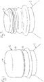
- Figure 5 is a perspective view of a further example of a container 1, a closing member 3 and a closure cap 2.
- the closure cap 2 again has a conventional outer appearance.
- the closing member 3 comprises a fixing member 10 with two fixation zones 16.
- the passage element 13 comprises six bridges 14 with passages 15 in between.
- Figure 6 is a vertical section through the same closure assembly applied to the container 1. As can be seen in this figure the plug member 11 is formed conical to allow a material stored in the reservoir 7 to pour out easily through passages 15 between bridges 14.
Landscapes
- Engineering & Computer Science (AREA)
- Mechanical Engineering (AREA)
- Closures For Containers (AREA)
Claims (8)
- Verschlussanordnung, umfassend:eine Verschlusskappe (2), die dazu geeignet ist, am Hals eines Behälters (1) befestigt zu werden, um den Behälter zu verschließen, wobei die Kappe eine obere Wand (4) und eine von dieser herabhängende Einfassung (5) aufweist, ein an der Unterseite der oberen Wand innerhalb der Einfassung gebildetes und mit einer Abgabeöffnung (9) versehenes Reservoir (7) und ein Verschlussteil (3) zum Verschließen der Abgabeöffnung (9) des Reservoirs (7),wobei das Verschlussteil umfasst:- ein Befestigungsteil (10), wobei das Befestigungsteil (10) dazu geeignet ist, in den Hals des Behälters (1) mit einem Presssitz zu passen, wenn die Anordnung daran befestigt wird,- ein Stöpselteil (11), wobei das Stöpselteil (11) dazu geeignet ist, in ein offenes Ende (9) des Reservoirs (7) zu passen, um das Reservoir (7) zu verschließen, wenn die Verschlusskappe (2) und das Schließteil (3) zusammengefügt sind,- ein Durchgangselement (13), welches Stoff aus dem Reservoir (7) in den Behälter (1) abzugeben erlaubt, wobei der Presssitz derart ist, dass dann, wenn die Verschlusskappe (2) von dem Behälter (1) entfernt wird, das Schließteil (3) innerhalb des Halses des Behälters gehalten bleibt und von der Verschlusskappe getrennt ist, derart, dass die Abgabeöffnung (9) geöffnet ist und darin enthaltener Stoff in den Behälter abgegeben wird,dadurch gekennzeichnet, dass dieVerschlusskappe (2) mit Dichtungsmitteln (12, 26, 27) zum direkten Abdichten gegenüber dem Hals eines solchen Behälters (1), insbesondere mit einer ringförmigen Wand (12) versehen ist, die von der Unterseite der oberen Wand der Verschlusskappe (2) nach unten verläuft, um in dem Hals des Behälters dichtend zu passen, wobei ein oberes Ende des Befestigungsteils (10) unter dem oberen Rand (19) des Behälter-(1)-Halses liegt.
- Anordnung nach Anspruch 1, wobei die ringförmige Wand (12) eine konvexe Verschluss-Dichtungszone (25) umfasst, in der der Außendurchmesser der ringförmigen Wand größer ist als der Innendurchmesser des Behälterhalses.
- Anordnung nach Anspruch 1 oder 2, wobei das Befestigungsteil zumindest eine Befestigungszone (16) umfasst, in der der Außendurchmesser des Befestigungsteiles größer ist als der Innendurchmesser des Behälterhalses.
- Anordnung nach einem der Ansprüche 1 bis 3, wobei das Reservoir (7) durch eine ringförmige Reservoirwand (8) gebildet ist, die von der Unterseite der oberen Wand (4) der Verschlusskappe nach unten verläuft.
- Anordnung nach irgendeinem vorhergehenden Anspruch, wobei das Durchgangselement (13) eine Vielzahl von radialen Brücken (14) umfasst, wobei zwischen den radialen Brücken (14) Durchgänge (15) gebildet sind, derart, dass dann, wenn die Verschlusskappe (2) von dem Schließteil (3) getrennt ist, Stoff aus dem Reservoir (7) durch die Durchgänge (15) in den Behälter (1) abgegeben werden kann.
- Anordnung nach irgendeinem vorhergehenden Anspruch, wobei die axiale Länge des Reservoirs (7) hauptsächlich der Summe der axialen Länge (21) des Befestigungsteiles (10) und der axialen Länge (20) der ringförmigen Wand (12) entspricht.
- Anordnung nach irgendeinem vorhergehenden Anspruch, wobei die Verschlusskappe zumindest ein Zentrierungsglied (18) umfasst, welches von der Unterseite der oberen Wand radial auf der Außenseite des Reservoirs (7) liegend und radial auf der Innenseite der Wand (12) liegend nach unten verläuft.
- Anordnung nach irgendeinem vorhergehenden Anspruch in Kombination mit einem Behälter (1), der einen Hals mit einem Außenschraubgewinde aufweist, wobei die Verschlusskappe (2) auf der Innenseite der herabhängenden Einfassung (5) mit einem entsprechenden Schraubgewinde zur Befestigung der Anordnung an dem Behälter gebildet ist.
Priority Applications (1)
| Application Number | Priority Date | Filing Date | Title |
|---|---|---|---|
| EP10752539.6A EP2473418B1 (de) | 2009-09-04 | 2010-09-01 | Behälterverschlussanordnung |
Applications Claiming Priority (3)
| Application Number | Priority Date | Filing Date | Title |
|---|---|---|---|
| EP09169490A EP2292525A1 (de) | 2009-09-04 | 2009-09-04 | Behälterverschlussanordnung |
| PCT/EP2010/062801 WO2011026861A1 (en) | 2009-09-04 | 2010-09-01 | Container closure assembly |
| EP10752539.6A EP2473418B1 (de) | 2009-09-04 | 2010-09-01 | Behälterverschlussanordnung |
Publications (2)
| Publication Number | Publication Date |
|---|---|
| EP2473418A1 EP2473418A1 (de) | 2012-07-11 |
| EP2473418B1 true EP2473418B1 (de) | 2017-05-24 |
Family
ID=41476009
Family Applications (2)
| Application Number | Title | Priority Date | Filing Date |
|---|---|---|---|
| EP09169490A Withdrawn EP2292525A1 (de) | 2009-09-04 | 2009-09-04 | Behälterverschlussanordnung |
| EP10752539.6A Not-in-force EP2473418B1 (de) | 2009-09-04 | 2010-09-01 | Behälterverschlussanordnung |
Family Applications Before (1)
| Application Number | Title | Priority Date | Filing Date |
|---|---|---|---|
| EP09169490A Withdrawn EP2292525A1 (de) | 2009-09-04 | 2009-09-04 | Behälterverschlussanordnung |
Country Status (3)
| Country | Link |
|---|---|
| US (1) | US9617050B2 (de) |
| EP (2) | EP2292525A1 (de) |
| WO (1) | WO2011026861A1 (de) |
Families Citing this family (20)
| Publication number | Priority date | Publication date | Assignee | Title |
|---|---|---|---|---|
| US20110278195A1 (en) * | 2010-05-12 | 2011-11-17 | Giocastro James V | Dual compartment dispenser |
| US20150266634A1 (en) * | 2014-03-19 | 2015-09-24 | Fang-Lin YANG | Bottle cap and container with bottle cap |
| USD752868S1 (en) * | 2014-04-24 | 2016-04-05 | Braun Gmbh | Electric toothbrush |
| UA120182C2 (uk) * | 2014-06-19 | 2019-10-25 | Гуала Клоужес С.П.А. | Кришка з камерою для зберігання |
| USD774392S1 (en) | 2015-05-26 | 2016-12-20 | Gordon Lauvi Alapa Broad | Chambered bottle cap |
| AU367126S (en) * | 2015-06-01 | 2016-02-15 | Obrist Closures Switzerland | Bottle neck finish |
| DE102015118053A1 (de) * | 2015-10-22 | 2017-04-27 | Rpc Bramlage Gmbh | Verschlusseinrichtung für einen Behälter |
| JP6647635B2 (ja) * | 2016-02-16 | 2020-02-14 | テアニン株式会社 | 混合容器 |
| KR102868835B1 (ko) * | 2016-04-28 | 2025-10-02 | 안진희 | 병마개 차단판 하부면의 이너링과 용기입구 내벽에 의한 차단 장치 |
| KR101889790B1 (ko) * | 2016-11-03 | 2018-09-28 | 제이씨텍(주) | 내열용기마개 |
| CN109963794B (zh) | 2016-11-14 | 2020-11-24 | 吉兹摩包装有限公司 | 用于闭合设备中的加压罐的阀装置 |
| CN108357778B (zh) * | 2017-01-26 | 2021-12-28 | 本诺瓦公司 | 将产品分配在容器中的盒 |
| DE102018105321A1 (de) * | 2017-03-10 | 2018-09-13 | Rpc Bramlage Gmbh | Verschlussvorrichtung für einen Behälter |
| TWI626198B (zh) * | 2017-04-14 | 2018-06-11 | Yang Fang Lin | Cover and container having the cover |
| CA3025161A1 (en) * | 2017-11-22 | 2019-05-22 | Craig Gordon Stewart | Cap insert with internal compartment |
| US11203471B2 (en) | 2018-05-21 | 2021-12-21 | Espirit Innovations, LLC | Pill bottle with removable pill container cap |
| CA3153474C (en) * | 2019-04-12 | 2024-01-23 | Elc Management Llc | Reconfigurable container-closure system |
| US20230065826A1 (en) * | 2021-08-27 | 2023-03-02 | Vectornate Usa Inc. | Container assembly for collecting biological specimens |
| MX2024012866A (es) * | 2022-04-20 | 2024-12-06 | Origin Mat Operating Inc | Cierres de resina de poliéster para recipientes |
| CN119873127A (zh) * | 2025-01-26 | 2025-04-25 | 海普智联科技股份有限公司 | 混合瓶盖及容器 |
Family Cites Families (18)
| Publication number | Priority date | Publication date | Assignee | Title |
|---|---|---|---|---|
| US3924741A (en) * | 1975-03-04 | 1975-12-09 | Gibson Ass Inc | Two-compartment container |
| FR2630997B1 (fr) * | 1988-05-04 | 1990-09-14 | Tecnoma | Dispositif pour introduire une quantite dosee d'un produit a l'interieur d'une enceinte |
| FI102642B (fi) * | 1996-06-19 | 1999-01-15 | Orion Diagnostica Oy | Reaktioastian tai vastaavan tulppa |
| MX203911B (es) * | 1997-05-21 | 2001-08-24 | Pablo Andres Robles Gonzalez | Aparato contenedor de substancias solubles en medios fluidos y metodo para la preparacion de mezclas en sitio. |
| US6003728A (en) * | 1998-10-22 | 1999-12-21 | Aptargroup, Inc. | Dispensing structure with an openable member for separating two products |
| DE29820062U1 (de) | 1998-11-10 | 1999-02-25 | Käsmacher GmbH & Co. KG, 52222 Stolberg | Zweikomponenten-Behältnis |
| DE10202147A1 (de) * | 2002-01-17 | 2003-09-18 | Birkmayer Gesundheitsprodukte | Kunststoff-Flaschenverschluss |
| US6994211B2 (en) | 2003-04-12 | 2006-02-07 | Young Kook Cho | Cap device for mixing different kinds of materials separately contained therein and in bottle |
| US6908011B2 (en) * | 2003-04-12 | 2005-06-21 | Young Kook Cho | Cap device for mixing different kinds of materials separately contained therein and in bottle |
| JP2004338751A (ja) | 2003-05-15 | 2004-12-02 | Nippon Tansan Gas Co Ltd | 原料を隔離して収容する容器の封止機構及び封止方法 |
| US8215505B2 (en) * | 2004-03-08 | 2012-07-10 | Lee Jeong-Min | Structure of cap having storage space |
| WO2005097615A1 (en) * | 2004-04-08 | 2005-10-20 | Jeong-Min Lee | Structure of cap having inner cap |
| KR200363704Y1 (ko) * | 2004-07-01 | 2004-10-06 | 임효빈 | 오픈시 내용물 혼합이 가능하도록 하는 덮개 |
| CN101080349A (zh) * | 2004-11-04 | 2007-11-28 | Viz企业有限责任公司 | 多室容器及其盖 |
| US7651004B2 (en) * | 2005-05-12 | 2010-01-26 | Rexam Closure Systems Inc. | Linerless closure and package |
| EP1752381A1 (de) | 2005-08-12 | 2007-02-14 | Obrist Closures Switzerland GmbH | Behälter-Verschluss |
| US7588142B1 (en) * | 2005-11-18 | 2009-09-15 | Rexam Closures And Containers Inc. | Additive delivery system closure |
| US7891512B2 (en) * | 2006-12-06 | 2011-02-22 | Reckitt Benckiser Inc. | Linerless closure for a container |
-
2009
- 2009-09-04 EP EP09169490A patent/EP2292525A1/de not_active Withdrawn
-
2010
- 2010-09-01 WO PCT/EP2010/062801 patent/WO2011026861A1/en not_active Ceased
- 2010-09-01 US US13/393,635 patent/US9617050B2/en not_active Expired - Fee Related
- 2010-09-01 EP EP10752539.6A patent/EP2473418B1/de not_active Not-in-force
Also Published As
| Publication number | Publication date |
|---|---|
| US9617050B2 (en) | 2017-04-11 |
| US20120152770A1 (en) | 2012-06-21 |
| EP2292525A1 (de) | 2011-03-09 |
| EP2473418A1 (de) | 2012-07-11 |
| WO2011026861A1 (en) | 2011-03-10 |
Similar Documents
| Publication | Publication Date | Title |
|---|---|---|
| EP2473418B1 (de) | Behälterverschlussanordnung | |
| EP1919791B1 (de) | Behälterverschlussanordnung | |
| AU2007246847B2 (en) | Container closure having means for introducing an additive into the contents of the container | |
| US9045269B2 (en) | Container closure having means for introducing an additive into the contents of the container | |
| EP3393923B1 (de) | Verschluss | |
| US20100012532A1 (en) | Container closure having a spout and means for introducing an additive into the contents of the container | |
| US20090321286A1 (en) | Container closure having a lifting cap for introducing an additive into the contents of the container | |
| US20050279653A1 (en) | Device for dispensing material into a container | |
| US20090020546A1 (en) | Tamper Resistant Closures | |
| EP1727739B1 (de) | Volumetrischer spender | |
| US20070267442A1 (en) | Infusion cap | |
| AU2005239651A1 (en) | Drinking spout and closure combination for a beverage container | |
| US12534246B2 (en) | Refill system and spout and methods of using the same | |
| EP2208684A1 (de) | Lufteinlassventil für Behälter mit Flüssigprodukten | |
| JP7479770B2 (ja) | 容器用キャップ | |
| JP2018111500A (ja) | 詰め替え用容器 | |
| RU114672U1 (ru) | Узел закупоривания бутылки | |
| MXPA97006347A (en) | Plug of inviolable and irrelenable type for bottles or simila containers |
Legal Events
| Date | Code | Title | Description |
|---|---|---|---|
| PUAI | Public reference made under article 153(3) epc to a published international application that has entered the european phase |
Free format text: ORIGINAL CODE: 0009012 |
|
| 17P | Request for examination filed |
Effective date: 20120222 |
|
| AK | Designated contracting states |
Kind code of ref document: A1 Designated state(s): AL AT BE BG CH CY CZ DE DK EE ES FI FR GB GR HR HU IE IS IT LI LT LU LV MC MK MT NL NO PL PT RO SE SI SK SM TR |
|
| DAX | Request for extension of the european patent (deleted) | ||
| 17Q | First examination report despatched |
Effective date: 20140305 |
|
| GRAP | Despatch of communication of intention to grant a patent |
Free format text: ORIGINAL CODE: EPIDOSNIGR1 |
|
| STAA | Information on the status of an ep patent application or granted ep patent |
Free format text: STATUS: GRANT OF PATENT IS INTENDED |
|
| INTG | Intention to grant announced |
Effective date: 20161207 |
|
| GRAS | Grant fee paid |
Free format text: ORIGINAL CODE: EPIDOSNIGR3 |
|
| GRAA | (expected) grant |
Free format text: ORIGINAL CODE: 0009210 |
|
| STAA | Information on the status of an ep patent application or granted ep patent |
Free format text: STATUS: THE PATENT HAS BEEN GRANTED |
|
| AK | Designated contracting states |
Kind code of ref document: B1 Designated state(s): AL AT BE BG CH CY CZ DE DK EE ES FI FR GB GR HR HU IE IS IT LI LT LU LV MC MK MT NL NO PL PT RO SE SI SK SM TR |
|
| REG | Reference to a national code |
Ref country code: GB Ref legal event code: FG4D |
|
| REG | Reference to a national code |
Ref country code: CH Ref legal event code: EP |
|
| REG | Reference to a national code |
Ref country code: IE Ref legal event code: FG4D |
|
| REG | Reference to a national code |
Ref country code: AT Ref legal event code: REF Ref document number: 895913 Country of ref document: AT Kind code of ref document: T Effective date: 20170615 |
|
| REG | Reference to a national code |
Ref country code: DE Ref legal event code: R096 Ref document number: 602010042561 Country of ref document: DE |
|
| REG | Reference to a national code |
Ref country code: NL Ref legal event code: MP Effective date: 20170524 |
|
| REG | Reference to a national code |
Ref country code: FR Ref legal event code: PLFP Year of fee payment: 8 |
|
| REG | Reference to a national code |
Ref country code: LT Ref legal event code: MG4D |
|
| REG | Reference to a national code |
Ref country code: AT Ref legal event code: MK05 Ref document number: 895913 Country of ref document: AT Kind code of ref document: T Effective date: 20170524 |
|
| PG25 | Lapsed in a contracting state [announced via postgrant information from national office to epo] |
Ref country code: FI Free format text: LAPSE BECAUSE OF FAILURE TO SUBMIT A TRANSLATION OF THE DESCRIPTION OR TO PAY THE FEE WITHIN THE PRESCRIBED TIME-LIMIT Effective date: 20170524 Ref country code: ES Free format text: LAPSE BECAUSE OF FAILURE TO SUBMIT A TRANSLATION OF THE DESCRIPTION OR TO PAY THE FEE WITHIN THE PRESCRIBED TIME-LIMIT Effective date: 20170524 Ref country code: LT Free format text: LAPSE BECAUSE OF FAILURE TO SUBMIT A TRANSLATION OF THE DESCRIPTION OR TO PAY THE FEE WITHIN THE PRESCRIBED TIME-LIMIT Effective date: 20170524 Ref country code: HR Free format text: LAPSE BECAUSE OF FAILURE TO SUBMIT A TRANSLATION OF THE DESCRIPTION OR TO PAY THE FEE WITHIN THE PRESCRIBED TIME-LIMIT Effective date: 20170524 Ref country code: NO Free format text: LAPSE BECAUSE OF FAILURE TO SUBMIT A TRANSLATION OF THE DESCRIPTION OR TO PAY THE FEE WITHIN THE PRESCRIBED TIME-LIMIT Effective date: 20170824 Ref country code: AT Free format text: LAPSE BECAUSE OF FAILURE TO SUBMIT A TRANSLATION OF THE DESCRIPTION OR TO PAY THE FEE WITHIN THE PRESCRIBED TIME-LIMIT Effective date: 20170524 Ref country code: GR Free format text: LAPSE BECAUSE OF FAILURE TO SUBMIT A TRANSLATION OF THE DESCRIPTION OR TO PAY THE FEE WITHIN THE PRESCRIBED TIME-LIMIT Effective date: 20170825 |
|
| PG25 | Lapsed in a contracting state [announced via postgrant information from national office to epo] |
Ref country code: BG Free format text: LAPSE BECAUSE OF FAILURE TO SUBMIT A TRANSLATION OF THE DESCRIPTION OR TO PAY THE FEE WITHIN THE PRESCRIBED TIME-LIMIT Effective date: 20170824 Ref country code: IS Free format text: LAPSE BECAUSE OF FAILURE TO SUBMIT A TRANSLATION OF THE DESCRIPTION OR TO PAY THE FEE WITHIN THE PRESCRIBED TIME-LIMIT Effective date: 20170924 Ref country code: SE Free format text: LAPSE BECAUSE OF FAILURE TO SUBMIT A TRANSLATION OF THE DESCRIPTION OR TO PAY THE FEE WITHIN THE PRESCRIBED TIME-LIMIT Effective date: 20170524 Ref country code: NL Free format text: LAPSE BECAUSE OF FAILURE TO SUBMIT A TRANSLATION OF THE DESCRIPTION OR TO PAY THE FEE WITHIN THE PRESCRIBED TIME-LIMIT Effective date: 20170524 Ref country code: LV Free format text: LAPSE BECAUSE OF FAILURE TO SUBMIT A TRANSLATION OF THE DESCRIPTION OR TO PAY THE FEE WITHIN THE PRESCRIBED TIME-LIMIT Effective date: 20170524 |
|
| PG25 | Lapsed in a contracting state [announced via postgrant information from national office to epo] |
Ref country code: DK Free format text: LAPSE BECAUSE OF FAILURE TO SUBMIT A TRANSLATION OF THE DESCRIPTION OR TO PAY THE FEE WITHIN THE PRESCRIBED TIME-LIMIT Effective date: 20170524 Ref country code: SK Free format text: LAPSE BECAUSE OF FAILURE TO SUBMIT A TRANSLATION OF THE DESCRIPTION OR TO PAY THE FEE WITHIN THE PRESCRIBED TIME-LIMIT Effective date: 20170524 Ref country code: CZ Free format text: LAPSE BECAUSE OF FAILURE TO SUBMIT A TRANSLATION OF THE DESCRIPTION OR TO PAY THE FEE WITHIN THE PRESCRIBED TIME-LIMIT Effective date: 20170524 Ref country code: EE Free format text: LAPSE BECAUSE OF FAILURE TO SUBMIT A TRANSLATION OF THE DESCRIPTION OR TO PAY THE FEE WITHIN THE PRESCRIBED TIME-LIMIT Effective date: 20170524 Ref country code: RO Free format text: LAPSE BECAUSE OF FAILURE TO SUBMIT A TRANSLATION OF THE DESCRIPTION OR TO PAY THE FEE WITHIN THE PRESCRIBED TIME-LIMIT Effective date: 20170524 |
|
| REG | Reference to a national code |
Ref country code: DE Ref legal event code: R097 Ref document number: 602010042561 Country of ref document: DE |
|
| PG25 | Lapsed in a contracting state [announced via postgrant information from national office to epo] |
Ref country code: PL Free format text: LAPSE BECAUSE OF FAILURE TO SUBMIT A TRANSLATION OF THE DESCRIPTION OR TO PAY THE FEE WITHIN THE PRESCRIBED TIME-LIMIT Effective date: 20170524 Ref country code: SM Free format text: LAPSE BECAUSE OF FAILURE TO SUBMIT A TRANSLATION OF THE DESCRIPTION OR TO PAY THE FEE WITHIN THE PRESCRIBED TIME-LIMIT Effective date: 20170524 |
|
| PLBE | No opposition filed within time limit |
Free format text: ORIGINAL CODE: 0009261 |
|
| STAA | Information on the status of an ep patent application or granted ep patent |
Free format text: STATUS: NO OPPOSITION FILED WITHIN TIME LIMIT |
|
| REG | Reference to a national code |
Ref country code: CH Ref legal event code: PL |
|
| 26N | No opposition filed |
Effective date: 20180227 |
|
| PG25 | Lapsed in a contracting state [announced via postgrant information from national office to epo] |
Ref country code: SI Free format text: LAPSE BECAUSE OF FAILURE TO SUBMIT A TRANSLATION OF THE DESCRIPTION OR TO PAY THE FEE WITHIN THE PRESCRIBED TIME-LIMIT Effective date: 20170524 Ref country code: MC Free format text: LAPSE BECAUSE OF FAILURE TO SUBMIT A TRANSLATION OF THE DESCRIPTION OR TO PAY THE FEE WITHIN THE PRESCRIBED TIME-LIMIT Effective date: 20170524 |
|
| REG | Reference to a national code |
Ref country code: IE Ref legal event code: MM4A |
|
| REG | Reference to a national code |
Ref country code: BE Ref legal event code: MM Effective date: 20170930 |
|
| PG25 | Lapsed in a contracting state [announced via postgrant information from national office to epo] |
Ref country code: LU Free format text: LAPSE BECAUSE OF NON-PAYMENT OF DUE FEES Effective date: 20170901 |
|
| PG25 | Lapsed in a contracting state [announced via postgrant information from national office to epo] |
Ref country code: IE Free format text: LAPSE BECAUSE OF NON-PAYMENT OF DUE FEES Effective date: 20170901 Ref country code: CH Free format text: LAPSE BECAUSE OF NON-PAYMENT OF DUE FEES Effective date: 20170930 Ref country code: LI Free format text: LAPSE BECAUSE OF NON-PAYMENT OF DUE FEES Effective date: 20170930 |
|
| PG25 | Lapsed in a contracting state [announced via postgrant information from national office to epo] |
Ref country code: BE Free format text: LAPSE BECAUSE OF NON-PAYMENT OF DUE FEES Effective date: 20170930 |
|
| REG | Reference to a national code |
Ref country code: FR Ref legal event code: PLFP Year of fee payment: 9 |
|
| PG25 | Lapsed in a contracting state [announced via postgrant information from national office to epo] |
Ref country code: MT Free format text: LAPSE BECAUSE OF NON-PAYMENT OF DUE FEES Effective date: 20170901 |
|
| PG25 | Lapsed in a contracting state [announced via postgrant information from national office to epo] |
Ref country code: HU Free format text: LAPSE BECAUSE OF FAILURE TO SUBMIT A TRANSLATION OF THE DESCRIPTION OR TO PAY THE FEE WITHIN THE PRESCRIBED TIME-LIMIT; INVALID AB INITIO Effective date: 20100901 |
|
| PG25 | Lapsed in a contracting state [announced via postgrant information from national office to epo] |
Ref country code: CY Free format text: LAPSE BECAUSE OF NON-PAYMENT OF DUE FEES Effective date: 20170524 |
|
| PG25 | Lapsed in a contracting state [announced via postgrant information from national office to epo] |
Ref country code: MK Free format text: LAPSE BECAUSE OF FAILURE TO SUBMIT A TRANSLATION OF THE DESCRIPTION OR TO PAY THE FEE WITHIN THE PRESCRIBED TIME-LIMIT Effective date: 20170524 |
|
| PG25 | Lapsed in a contracting state [announced via postgrant information from national office to epo] |
Ref country code: TR Free format text: LAPSE BECAUSE OF FAILURE TO SUBMIT A TRANSLATION OF THE DESCRIPTION OR TO PAY THE FEE WITHIN THE PRESCRIBED TIME-LIMIT Effective date: 20170524 |
|
| PG25 | Lapsed in a contracting state [announced via postgrant information from national office to epo] |
Ref country code: PT Free format text: LAPSE BECAUSE OF FAILURE TO SUBMIT A TRANSLATION OF THE DESCRIPTION OR TO PAY THE FEE WITHIN THE PRESCRIBED TIME-LIMIT Effective date: 20170524 |
|
| PG25 | Lapsed in a contracting state [announced via postgrant information from national office to epo] |
Ref country code: AL Free format text: LAPSE BECAUSE OF FAILURE TO SUBMIT A TRANSLATION OF THE DESCRIPTION OR TO PAY THE FEE WITHIN THE PRESCRIBED TIME-LIMIT Effective date: 20170524 |
|
| PGFP | Annual fee paid to national office [announced via postgrant information from national office to epo] |
Ref country code: DE Payment date: 20200925 Year of fee payment: 11 Ref country code: FR Payment date: 20200914 Year of fee payment: 11 Ref country code: GB Payment date: 20200922 Year of fee payment: 11 |
|
| PGFP | Annual fee paid to national office [announced via postgrant information from national office to epo] |
Ref country code: IT Payment date: 20200924 Year of fee payment: 11 |
|
| REG | Reference to a national code |
Ref country code: DE Ref legal event code: R082 Ref document number: 602010042561 Country of ref document: DE Representative=s name: KILBURN & STRODE LLP, NL |
|
| REG | Reference to a national code |
Ref country code: DE Ref legal event code: R119 Ref document number: 602010042561 Country of ref document: DE |
|
| GBPC | Gb: european patent ceased through non-payment of renewal fee |
Effective date: 20210901 |
|
| PG25 | Lapsed in a contracting state [announced via postgrant information from national office to epo] |
Ref country code: GB Free format text: LAPSE BECAUSE OF NON-PAYMENT OF DUE FEES Effective date: 20210901 Ref country code: FR Free format text: LAPSE BECAUSE OF NON-PAYMENT OF DUE FEES Effective date: 20210930 Ref country code: DE Free format text: LAPSE BECAUSE OF NON-PAYMENT OF DUE FEES Effective date: 20220401 |
|
| PG25 | Lapsed in a contracting state [announced via postgrant information from national office to epo] |
Ref country code: IT Free format text: LAPSE BECAUSE OF NON-PAYMENT OF DUE FEES Effective date: 20210901 |