EP2473436B1 - Haltespange mit einer klammer zum ergreifen von flaschenhälsen - Google Patents
Haltespange mit einer klammer zum ergreifen von flaschenhälsen Download PDFInfo
- Publication number
- EP2473436B1 EP2473436B1 EP10724283.6A EP10724283A EP2473436B1 EP 2473436 B1 EP2473436 B1 EP 2473436B1 EP 10724283 A EP10724283 A EP 10724283A EP 2473436 B1 EP2473436 B1 EP 2473436B1
- Authority
- EP
- European Patent Office
- Prior art keywords
- clamp
- permanent magnet
- rotating
- retaining
- retaining pin
- Prior art date
- Legal status (The legal status is an assumption and is not a legal conclusion. Google has not performed a legal analysis and makes no representation as to the accuracy of the status listed.)
- Not-in-force
Links
- 210000003739 neck Anatomy 0.000 title claims description 5
- 238000013459 approach Methods 0.000 description 9
- 239000000945 filler Substances 0.000 description 4
- 238000012546 transfer Methods 0.000 description 3
- 238000013461 design Methods 0.000 description 2
- 230000003670 easy-to-clean Effects 0.000 description 1
- 238000012423 maintenance Methods 0.000 description 1
- 230000007246 mechanism Effects 0.000 description 1
- 238000000034 method Methods 0.000 description 1
- 230000001846 repelling effect Effects 0.000 description 1
Images

Classifications
-
- B—PERFORMING OPERATIONS; TRANSPORTING
- B67—OPENING, CLOSING OR CLEANING BOTTLES, JARS OR SIMILAR CONTAINERS; LIQUID HANDLING
- B67C—CLEANING, FILLING WITH LIQUIDS OR SEMILIQUIDS, OR EMPTYING, OF BOTTLES, JARS, CANS, CASKS, BARRELS, OR SIMILAR CONTAINERS, NOT OTHERWISE PROVIDED FOR; FUNNELS
- B67C3/00—Bottling liquids or semiliquids; Filling jars or cans with liquids or semiliquids using bottling or like apparatus; Filling casks or barrels with liquids or semiliquids
- B67C3/02—Bottling liquids or semiliquids; Filling jars or cans with liquids or semiliquids using bottling or like apparatus
- B67C3/22—Details
- B67C3/24—Devices for supporting or handling bottles
- B67C3/242—Devices for supporting or handling bottles engaging with bottle necks
-
- B—PERFORMING OPERATIONS; TRANSPORTING
- B65—CONVEYING; PACKING; STORING; HANDLING THIN OR FILAMENTARY MATERIAL
- B65G—TRANSPORT OR STORAGE DEVICES, e.g. CONVEYORS FOR LOADING OR TIPPING, SHOP CONVEYOR SYSTEMS OR PNEUMATIC TUBE CONVEYORS
- B65G47/00—Article or material-handling devices associated with conveyors; Methods employing such devices
- B65G47/74—Feeding, transfer, or discharging devices of particular kinds or types
- B65G47/84—Star-shaped wheels or devices having endless travelling belts or chains, the wheels or devices being equipped with article-engaging elements
- B65G47/846—Star-shaped wheels or wheels equipped with article-engaging elements
- B65G47/847—Star-shaped wheels or wheels equipped with article-engaging elements the article-engaging elements being grippers
-
- B—PERFORMING OPERATIONS; TRANSPORTING
- B65—CONVEYING; PACKING; STORING; HANDLING THIN OR FILAMENTARY MATERIAL
- B65G—TRANSPORT OR STORAGE DEVICES, e.g. CONVEYORS FOR LOADING OR TIPPING, SHOP CONVEYOR SYSTEMS OR PNEUMATIC TUBE CONVEYORS
- B65G47/00—Article or material-handling devices associated with conveyors; Methods employing such devices
- B65G47/74—Feeding, transfer, or discharging devices of particular kinds or types
- B65G47/90—Devices for picking-up and depositing articles or materials
Definitions
- the invention is directed to a retaining clip with a clamp for gripping bottle necks, in particular of PET bottles, according to the preamble of claim 1 and as from DE 10 2008 019 766 B3 known.
- the object of the present invention is in particular to expand the scope of corresponding clips or clips by these should not only be suitable for empty containers, but also for filled bottles or other receptacles with a corresponding neck design, so These staples can also be used in fillers and transfer stars between filler and capper.
- the mounting method is optimally maintained in the form of a plug-in system.
- the invention provides in an embodiment that in the clasp-like approach a permanent magnet is provided, which is positionable in the use position coaxial with the rotary sleeve of the clip and cooperates with the permanent magnet in the bracket.
- the invention also provides in an embodiment in that on the swivel body on the opposite side of the clasp-like approach, another approach is provided with a permanent magnet, which serves to stabilize the clip in the position of use.
- the invention has, as already indicated above, some special advantages.
- the bottle clamps can be quickly exchanged, for example, without tools, they are easy to clean, inexpensive to retrofit and can be used as standard parts versatile on a variety of investment elements, such as the star, the rinser, the transfer star in the filler and the star in front of the capper, resulting in significant cost savings ,
- the clip is always magnetically pivoted into the locked position so that machine damage due to incorrect operation can be ruled out.
- brackets 2 according to the invention are pushed from the bottom first rotation and retaining bolts, in rotary sleeves plunge.
- the clip 2 has been floated for transporting a PET bottle 4, but it can also grip and convey other containers, including the corresponding necks, in Fig. 1 denoted by 4a, takes hold.
- a second turning and holding bolt 5 is fixed, which is encompassed by a pivotable sleeve 6, on which a clasp 7 is formed, with its free approach 7a. which is optionally equipped with a permanent magnet 8, under the rotary sleeve 3, which is assigned to the bracket 2, is pivoted.
- the two pivot positions arise from the Fig. 1 and 2 ,
- the rotary sleeve 3 of the bracket has an integrally formed projection 3a, which in turn may be equipped with a permanent magnet to cooperate with the retaining bolt 5 and the corresponding sleeve, which in turn may include a permanent magnet.
- the bracket 2 with its rotary sleeve 3 and the molded-on projection 3a is pushed during assembly from below on the corresponding pivot and retaining bolts on Meschinenelement 1, after the pivot body 6 has been pushed over the second rotating and retaining pin 5 on the machine element.
- To fix the free approach 7a is then pivoted under the rotary sleeve 3 of the bracket 2, as turn this off Fig. 1 results in order to apply an additional holding force against slipping of the bracket 2.
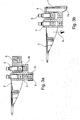
- Fig. 3a and 3b are the two out Fig. 1 and Fig. 2 apparent positions of the swivel body 6 with clasp 7 and free approach 7a shown in section indicating the possibly provided different magnets.
- Fig. 3a is shown by the clip lock position shown.
- the magnet H1 is firmly seated in a corresponding sleeve on the star, not shown, the magnet H2 is firmly seated in the bracket 2, both of which hold the clamp 2 in an attractive manner. If this fixation already suffices to hold the clamp itself with empty bottles, the free projection 7a with a permanent magnet 8 or "S1" is pivoted under the rotary sleeve 3 to exert a larger holding force and thus can exert an additional holding force.
- This magnet S1 is firmly seated in the free shoulder 7a of the clasp 7 in the locked position.
- Fig. 3b is the situation according to Fig. 2 represented, in which the clasp 7 is pivoted away with approach 7a, so that the rotary sleeve 3 with the bracket 2 can be pulled down, for example for maintenance od.
- the Abziehitzkeit down is indicated by an arrow 9
- the projection 7a of the clasp 7 may be designed without permanent magnet 8 and be shaped so that it secures the rotary sleeve 3 of the bracket 2 from below.
Landscapes
- Engineering & Computer Science (AREA)
- Mechanical Engineering (AREA)
- Filling Of Jars Or Cans And Processes For Cleaning And Sealing Jars (AREA)
- Sealing Of Jars (AREA)
Description
- Die Erfindung richtet sich auf eine Haltespange mit einer Klammer zum Ergreifen von Flaschenhälsen, insbesondere von PET-Flaschen, gemäß dem Oberbegriff des Anspruchs 1 und wie aus der
DE 10 2008 019 766 B3 bekannt. - Eine Klammer ist in der am 20.05.2010 veröffentlichten Anmeldung
DE 10 2008 055 617 der Anmelderin beschrieben. - Wie dort beschrieben, gibt es derartige Klammern in sehr unterschieblichen Ausgestaltungen. So zeigt beispielsweise die
DE 10 2006 012 020 A1 ein Klammerpaar. wobei die beiden Klammerarme in ungetrennte Achsen schwenkbar sind und die Schließkraft mittels einer Feder in Schließstellung gehalten wird. Da derartige Federetemente häufig den an Flaschenabfüllanlagen geforderten Forderungen der Hygiene nicht gerecht werden, ist man bemüht, andere Schließmechanismen vorzuschlagen. So sieht in einer aufwändigen Gestaltung dieDE 10 2005 041 929 A1 Dauermagnete vor, die in unterschiedlichen Paarungen sowohl das Schließen als auch das Öffnen unterstützen. In dieser Lösung sind die Dauermagneten außerhalb der Klammergreifarme positioniert. - Zur Unterstützung der Öffnungskraft der Klammern sieht eine Lösung nach der
DE 20 2005 002 924 U1 oder derDE 10 2005 014 838 A1 vor, dass zwischen Greifbereich der Klammern und Schwenkachsen sich abstoßende Magneten positioniert sind. - Die Aufgabe der vorliegenden Erfindung besteht darin, insbesondere den Anwendungsbereich von entsprechenden Klammern bzw. Clipsen zu erweitern, indem diese nicht nur für leere Behälter geeignet sein sollen, sondern auch für gefüllte Flaschen oder andere Aufnahmebehälter mit entsprechender Halsgestaltung, so dass diese Klammern zusätzlich in Füller und Transfersternen zwischen Füller und Verschließer eingesetzt werden können.
- Eine derartige Aufgabe wird nach der Erfindung durch die Merkmale des Hauptanspruches gelöst.
- Durch das Vorsehen eines Schwenkkörper mit einem unter die Klammer greifenden Ansatz wird ein zusätzliches Sicherungselement bereitgestellt, so dass auch schwerere Objekte aufgenommen werden können, ohne dass die Gefahr des Lösens der Klammern aus der entsprechenden Dreh- bzw. Fördereinrichtung möglich wird. Zusätzlich wird die Montageweise in Form eines Stecksystems optimal beibehalten.
- Zur Verstärkung der Haltekräfte sieht die Erfindung in Ausgestaltung vor, dass im spangenartigen Ansatz ein Dauermagnet vorgesehen ist, der in der Gebrauchslage koaxial zur Drehhülse der Klammer positionierbar ist und mit dem Dauermagneten in der Klammer zusammenwirkt.
- Die Erfindung sieht in Ausgestaltung auch vor, dass an dem Schwenkkörper auf der dem spangenartigen Ansatz gegenüberliegenden Seite ein weiterer Ansatz mit einem Dauermagneten vorgesehen ist, der zur Stabilisierung der Klammer in der Gebrauchslage dient.
- Die Erfindung weist, wie oben schon angedeutet, einige besondere Vorteile auf. Die Flaschenklammern sind z.B. ohne Werkzeug schnell auswechselbar, sie sind gut zu reinigen, kostengünstig nachrüstbar und können als Standardteilevielseitig verwendet werden an unterschiedlichsten Anlageelementen, wie im Stern, dem Rinser, dem Transferstern im Füller und dem Stern vor dem Verschließer, was zur erheblichen Kosteneinsparung führt. Zusätzlich wird die Klammer magnetisch immer in die Sperrlage verschwenkt, so dass Maschinenschäden durch Fehlbedienung ausgeschlossen werden können.
- Weitere Einzelheiten, Merkmale und Vorteile der Erfindung ergeben sich aufgrund der nachfolgenden Beschreibung sowie anhand der Zeichnung. Diese zeigt in
-
Fig. 1 die Unteransicht eines Förderelementes mit erfindungsgemäßer Klammer und einer aufgenommenen Flasche, -
Fig. 2 eine Unteransicht in räumlicher Darstellung mit Klammer ohne Flasche mit weggeschwenktern spangenförmigen Einsatz sowie in -
Fig. 3a und 3b einen Schnitt gemäß Linie III-III inFig. 2 durch die Haltespange in zwei unterschiedlichen Positionen des Sicherungsansatzes. - An einem Maschinenelement, wie ein Stern z.B, das beispielsweise ein Element eines Füllers, eines Verschließers od. dgl. darstellen kann, worauf es hier nicht näher ankommt, sind die erfindungsgemäßen Klammern 2 von unten auferste Dreh- und Haltebolzen aufgeschoben, die in Drehhülsen 3 eintauchen.
- Die Klammer 2 ist beispielsweise zum Transport einer PET-Flasche 4 ausgetegt, sie kann aber auch andere Behälter greifen und fördern, wobei sie die entsprechenden Hälse, in
Fig. 1 mit 4a bezeichnet, ergreift. Am Maschinenelement 1 ist ein zweiter Dreh- und Haltebolzen 5 fixiert, der von einer schwenkbaren Hülse 6 umgriffen wird, an der eine Spange 7 angeformt ist, die mit ihrem freien Ansatz 7a. der ggf. mit einem Dauermagneten 8 ausgerüstet ist, unter die Drehhülse 3, die der Klammer 2 zugeordnet ist, verschwenkt ist. Die beiden Schwenkpositionen ergeben sich aus denFig. 1 und 2 . - Die Drehhülse 3 der Klammer weist einen einstückig angeformten Ansatz 3a auf, der wiederum mit einem Dauermagneten ausgerüstet sein kann, um mit dem Haltebolzen 5 bzw. der entsprechenden Hülse zusammenzuwirken, die ihrerseits wiederum einen Dauermagneten beinhalten kann.
- Die Klammer 2 mit ihrer Drehhülse 3 und dem angeformten Ansatz 3a wird bei der Montage von unten über den entsprechenden Dreh- und Haltebolzen am Mäschinenelement 1 geschoben, nachdem der Schwenkkörper 6 über den zweiten Dreh-und Haltebolzen 5 am Maschinenelement geschoben wurde. Zur Fixierung wird dann der freie Ansatz 7a unter die Drehhülse 3 der Klammer 2 verschwenkt, wie sich dies aus
Fig. 1 ergibt, um eine zusätzliche Haltekraft gegen Abrutschen der Klammer 2 aufzubringen. - In den
Fig. 3a und 3b sind die beiden ausFig. 1 und Fig. 2 ersichtlichen Positionen des Schwenkkörpers 6 mit Spange 7 und freiem Ansatz 7a im Schnitt dargestellt mit Angabe der ggf. vorgesehenen unterschiedlichen Magnete. - In
Fig. 3a ist die durch die Spange erfolgte Verriegelungsstellung dargestellt. Der Magnet H1 sitzt fest in einer entsprechenden Hülse am nicht näher dargestellten Stern, der Magnet H2 sitzt fest in der Klammer 2, die beide entsprechend anziehend die Klammer 2 halten. Reicht diese Fixierung bereits aus, um die Klammer selbst mit leeren Flaschen zu halten, so ist zur Ausübung einer größeren Haltekraft der freie Ansatz 7a mit einem Dauemagneten 8 bzw. "S1" unter die Drehhülse 3 geschwenkt und vermag damit eine zusätzliche Haltekraft auszuüben. Dieser Magnet S1 sitzt fest in dem freien Ansatz 7a der Spange 7 in Sperrposition. - In
Fig. 3b ist die Situation gemäßFig. 2 dargestellt, bei der die Spange 7 mit Ansatz 7a weggeschwenkt ist, so dass die Drehhülse 3 mit der Klammer 2 nach unten abgezogen werden kann, z.B. zu Wartungsarbeiten od. dgl. Die Abziehmöglichkeit nach unten ist durch einen Pfeil 9 angedeutet - Natürlich ist das beschriebene Ausführungsbeispiel der Erfindung noch in vielfacher Hinsicht abzuändern, ohne den Grundgedanken zu verlassen. So kann beispielsweise der Ansatz 7a der Spange 7 ohne Dauermagnet 8 gestaltet sein und so geformt sein, dass er von unten die Drehhülse 3 der Klammer 2 sichert.
-
- 1
- Stern (Maschinenelement, Transferstern etc.)
- 2
- Klammer
- 3
- Drehhülsen
- 4
- PET-Flasche
- 4a
- Flaschenhals
- 5
- Zweiter Dreh- und Haltebolzen
- 6
- Schwenkkörper
- 7, 7a
- Spange, freier Ansatz
- 8
- Dauermagnet
Claims (3)
- Haltespange mit einer Klammer (2) mit Klammerarmen zum Ergreifen von Flaschenhälsen (4a), insbesondere von PET-Flaschen (4), in Flaschenabfüllanlagen mit den Merkmalen;- die Klammerarme sind in horizontaler Ebene verschwenkbar, wobei die Klammer (2) eine Drehhülse (3) zum Übergreifen eines in die Drehhülse von oben eingreifenden ersten Dreh- und Haltebolzens an einen Stern (1) oder dergleichen aufweist,gekennzeicht durch die Merkmale:- der erste Dreh- und Haltebolzen ist mit einem magnetisierbaren (H1) oder magnetischfreien Ende ausgestattet,- im unteren Bereich der Drehhülse (3) ist ein mit dem ersten Dreh- und Haltebolzen zusammenwirkender Dauermagnet (H2) positioniert,- am Stern (1) oder dergleichen ist ein zweiter Dreh- und Haltebolzen (5) parallel zum ersten Dreh- und Haltebolzen mit einem eine anziehende Kraft ausübenden Dauermagneten (Z1) oder einem von einem Magneten beeinflussbaren Bereich an seinem freien Ende zur Zentrierung und Rückstellung der Klammer vorgesehen,- dieser zweite Dreh- und Haltebolzen (5) ist von einem Schwenkkörper (6) umgeben, indem eine Spange (7) angeformt ist, die mit einerm freien und in der Gebrauchslage unter die Klammer (2) greifenden Ansatz (7a) versehen ist.
- Haltespange nach Anspruch 1, dadurch gekennzeichnet, dass im freien Ansatz (7a) ein Dauermagnet (8, S1) vorgesehen ist, der in der Gebrauchslage koaxial zur Drehhülse (3) der Klammer (2) positionierbar ist und mit dem Dauermagneten (H2) in der Klammer (2) zusammenwirkt.
- Haltespange nach Anspruch 1 oder 2, dadurch gekennzeichnet, dass an dem Schwenkkörper (6) auf der dem Ansatz (7a) gegenüberliegenden Seite ein weiterer Ansatz mit einem Dauermagneten vorgesehen ist, der zur Stabilisierung der Klammer in der Gebrauchslage dient.
Applications Claiming Priority (2)
| Application Number | Priority Date | Filing Date | Title |
|---|---|---|---|
| DE102009038987A DE102009038987B3 (de) | 2009-08-31 | 2009-08-31 | Haltespange mit einer Klammer, insbesondere zum Ergreifen von Flaschenhälsen bei PET-Flaschen |
| PCT/EP2010/003149 WO2011023253A1 (de) | 2009-08-31 | 2010-05-21 | Haltespange mit einer klammer zum ergreifen von flaschenhälsen |
Publications (2)
| Publication Number | Publication Date |
|---|---|
| EP2473436A1 EP2473436A1 (de) | 2012-07-11 |
| EP2473436B1 true EP2473436B1 (de) | 2015-03-25 |
Family
ID=42735798
Family Applications (1)
| Application Number | Title | Priority Date | Filing Date |
|---|---|---|---|
| EP10724283.6A Not-in-force EP2473436B1 (de) | 2009-08-31 | 2010-05-21 | Haltespange mit einer klammer zum ergreifen von flaschenhälsen |
Country Status (4)
| Country | Link |
|---|---|
| US (1) | US8844586B2 (de) |
| EP (1) | EP2473436B1 (de) |
| DE (1) | DE102009038987B3 (de) |
| WO (1) | WO2011023253A1 (de) |
Families Citing this family (7)
| Publication number | Priority date | Publication date | Assignee | Title |
|---|---|---|---|---|
| DE102012111753B3 (de) * | 2012-12-04 | 2013-11-28 | Khs Gmbh | Vorrichtung zum Greifen und Halten von Behältern |
| DE102012111754B4 (de) * | 2012-12-04 | 2015-12-31 | Khs Gmbh | Schwenksperre für Flaschengreifer |
| DE102017108926B4 (de) * | 2017-04-26 | 2023-08-03 | Khs Gmbh | Vorrichtung zum Transportieren von Behältern |
| IT201700047740A1 (it) | 2017-05-03 | 2018-11-03 | Arol Spa | Dispositivo di presa e centraggio di bottiglie per impianti di tappatura |
| ES1237999Y (es) * | 2019-10-18 | 2020-02-14 | Zumex Group S A | Conjunto soporte de botellas para maquina exprimidora o dispensadora de bebidas |
| EP4085020A1 (de) * | 2019-12-30 | 2022-11-09 | Sidel Participations | Befülleinheit und füllmaschine mit einer befülleinheit zum befüllen von behältern |
| CN119190538B (zh) * | 2024-10-18 | 2025-11-04 | 江苏新美星包装机械股份有限公司 | 一种恒弹力夹持机构及恒弹力夹持方法 |
Family Cites Families (9)
| Publication number | Priority date | Publication date | Assignee | Title |
|---|---|---|---|---|
| DE8705631U1 (de) | 1987-04-16 | 1988-08-18 | Holstein Und Kappert Ag, 4600 Dortmund | Vorrichtung zum Abfüllen von Gefäßen |
| DE202005002924U1 (de) * | 2005-02-23 | 2006-03-30 | Krones Ag | Klammergreifer für ein Gefäßtransportsystem |
| DE102005014838A1 (de) * | 2005-03-30 | 2006-10-05 | Krones Ag | Klammer zum Halten von Gefäßen |
| DE102005041929A1 (de) * | 2005-09-03 | 2007-03-08 | Krones Ag | Greifer für Behälter |
| DE102006012020A1 (de) * | 2006-03-14 | 2007-09-20 | Krones Ag | Verfahren und Vorrichtung zum Transportieren von Behältern |
| DE102008019766B3 (de) * | 2008-04-18 | 2009-04-23 | Khs Ag | Vorrichtung zum Greifen und Halten von PET-Flaschen |
| DE102008055618B4 (de) * | 2008-11-03 | 2010-12-30 | Khs Gmbh | Klammer zum Ergreifen von Flaschenhälsen, insbesondere von PET-Flaschen |
| DE102008055617B4 (de) | 2008-11-03 | 2015-08-27 | Khs Gmbh | Klammer zum Ergreifen von Flaschenhälsen, insbesondere von PET-Flaschen |
| DE102009050393B4 (de) * | 2009-10-22 | 2011-07-28 | KHS GmbH, 44143 | Behälterklammer bzw. -clip |
-
2009
- 2009-08-31 DE DE102009038987A patent/DE102009038987B3/de not_active Expired - Fee Related
-
2010
- 2010-05-21 US US13/320,929 patent/US8844586B2/en not_active Expired - Fee Related
- 2010-05-21 EP EP10724283.6A patent/EP2473436B1/de not_active Not-in-force
- 2010-05-21 WO PCT/EP2010/003149 patent/WO2011023253A1/de not_active Ceased
Also Published As
| Publication number | Publication date |
|---|---|
| EP2473436A1 (de) | 2012-07-11 |
| US20120056062A1 (en) | 2012-03-08 |
| WO2011023253A1 (de) | 2011-03-03 |
| DE102009038987B3 (de) | 2011-04-28 |
| US8844586B2 (en) | 2014-09-30 |
Similar Documents
| Publication | Publication Date | Title |
|---|---|---|
| EP2473436B1 (de) | Haltespange mit einer klammer zum ergreifen von flaschenhälsen | |
| EP2643250B1 (de) | Pet-flaschen-greifvorrichtung | |
| EP2628707B1 (de) | Verfahren und Vorrichtung zum Transportieren von Behältern | |
| EP2279143B1 (de) | Vorrichtung zum greifen und halten von pet-flaschen | |
| EP2379432B1 (de) | Behälterklammer bzw. -clip | |
| EP2424799B1 (de) | Vorrichtung zur übergabe von im neckbereich mittels greifern od. dgl. gehaltenen flaschen | |
| EP2473437B1 (de) | Greifer zum halten von gefässen wie pet-flaschen | |
| EP2352692B1 (de) | Vorrichtung zum greifen von pet-flaschen in flaschenabfüllanlagen oder dergleichen | |
| EP2295352A2 (de) | Greifeinheit zum Halten und Bewegen von Artikeln | |
| DE102012015886B3 (de) | Behältergreifer sowie Transportelement mit derartigen Behältergreifern | |
| EP3107846A1 (de) | Werkzeuglos befestigter schutzkörper zum schutz von glasflaschen in sterntaschen | |
| DE102020131105A1 (de) | Vorrichtung zum linearen Transportieren von Behältern | |
| EP1520813A1 (de) | Überleitvorrichtung für Behälterbehandlungsmaschinen | |
| EP2307293B1 (de) | Verfahren zur handhabung von behältern während des transportes durch abfüllanlagen | |
| EP2890624A1 (de) | Verfahren zum greifenden transport von behältern an einer behandlungs- und transportvorrichtung sowie behälter- und transportvorrichtung mit selbstadaptiven greifelementen | |
| EP3028986B1 (de) | Vorrichtung zum transportieren von behältern | |
| DE102022108164A1 (de) | Kettenführung für Behälter | |
| DE10247362A1 (de) | Neck-Handling-Transportstern für den Transport von Behältern | |
| DE202008008777U1 (de) | Individuell platzierbarer Halter für Gefäße zum Öffnen mit nur einer Hand |
Legal Events
| Date | Code | Title | Description |
|---|---|---|---|
| PUAI | Public reference made under article 153(3) epc to a published international application that has entered the european phase |
Free format text: ORIGINAL CODE: 0009012 |
|
| 17P | Request for examination filed |
Effective date: 20120331 |
|
| AK | Designated contracting states |
Kind code of ref document: A1 Designated state(s): AL AT BE BG CH CY CZ DE DK EE ES FI FR GB GR HR HU IE IS IT LI LT LU LV MC MK MT NL NO PL PT RO SE SI SK SM TR |
|
| DAX | Request for extension of the european patent (deleted) | ||
| GRAP | Despatch of communication of intention to grant a patent |
Free format text: ORIGINAL CODE: EPIDOSNIGR1 |
|
| GRAJ | Information related to disapproval of communication of intention to grant by the applicant or resumption of examination proceedings by the epo deleted |
Free format text: ORIGINAL CODE: EPIDOSDIGR1 |
|
| GRAP | Despatch of communication of intention to grant a patent |
Free format text: ORIGINAL CODE: EPIDOSNIGR1 |
|
| INTG | Intention to grant announced |
Effective date: 20141211 |
|
| INTG | Intention to grant announced |
Effective date: 20150106 |
|
| GRAS | Grant fee paid |
Free format text: ORIGINAL CODE: EPIDOSNIGR3 |
|
| GRAA | (expected) grant |
Free format text: ORIGINAL CODE: 0009210 |
|
| AK | Designated contracting states |
Kind code of ref document: B1 Designated state(s): AL AT BE BG CH CY CZ DE DK EE ES FI FR GB GR HR HU IE IS IT LI LT LU LV MC MK MT NL NO PL PT RO SE SI SK SM TR |
|
| REG | Reference to a national code |
Ref country code: GB Ref legal event code: FG4D Free format text: NOT ENGLISH |
|
| REG | Reference to a national code |
Ref country code: CH Ref legal event code: EP |
|
| REG | Reference to a national code |
Ref country code: IE Ref legal event code: FG4D Free format text: LANGUAGE OF EP DOCUMENT: GERMAN |
|
| REG | Reference to a national code |
Ref country code: DE Ref legal event code: R096 Ref document number: 502010009199 Country of ref document: DE Effective date: 20150507 |
|
| REG | Reference to a national code |
Ref country code: AT Ref legal event code: REF Ref document number: 717762 Country of ref document: AT Kind code of ref document: T Effective date: 20150515 |
|
| PG25 | Lapsed in a contracting state [announced via postgrant information from national office to epo] |
Ref country code: LT Free format text: LAPSE BECAUSE OF FAILURE TO SUBMIT A TRANSLATION OF THE DESCRIPTION OR TO PAY THE FEE WITHIN THE PRESCRIBED TIME-LIMIT Effective date: 20150325 Ref country code: HR Free format text: LAPSE BECAUSE OF FAILURE TO SUBMIT A TRANSLATION OF THE DESCRIPTION OR TO PAY THE FEE WITHIN THE PRESCRIBED TIME-LIMIT Effective date: 20150325 Ref country code: NO Free format text: LAPSE BECAUSE OF FAILURE TO SUBMIT A TRANSLATION OF THE DESCRIPTION OR TO PAY THE FEE WITHIN THE PRESCRIBED TIME-LIMIT Effective date: 20150625 Ref country code: FI Free format text: LAPSE BECAUSE OF FAILURE TO SUBMIT A TRANSLATION OF THE DESCRIPTION OR TO PAY THE FEE WITHIN THE PRESCRIBED TIME-LIMIT Effective date: 20150325 Ref country code: SE Free format text: LAPSE BECAUSE OF FAILURE TO SUBMIT A TRANSLATION OF THE DESCRIPTION OR TO PAY THE FEE WITHIN THE PRESCRIBED TIME-LIMIT Effective date: 20150325 |
|
| REG | Reference to a national code |
Ref country code: LT Ref legal event code: MG4D |
|
| PG25 | Lapsed in a contracting state [announced via postgrant information from national office to epo] |
Ref country code: GR Free format text: LAPSE BECAUSE OF FAILURE TO SUBMIT A TRANSLATION OF THE DESCRIPTION OR TO PAY THE FEE WITHIN THE PRESCRIBED TIME-LIMIT Effective date: 20150626 Ref country code: LV Free format text: LAPSE BECAUSE OF FAILURE TO SUBMIT A TRANSLATION OF THE DESCRIPTION OR TO PAY THE FEE WITHIN THE PRESCRIBED TIME-LIMIT Effective date: 20150325 |
|
| PG25 | Lapsed in a contracting state [announced via postgrant information from national office to epo] |
Ref country code: NL Free format text: LAPSE BECAUSE OF FAILURE TO SUBMIT A TRANSLATION OF THE DESCRIPTION OR TO PAY THE FEE WITHIN THE PRESCRIBED TIME-LIMIT Effective date: 20150325 |
|
| PG25 | Lapsed in a contracting state [announced via postgrant information from national office to epo] |
Ref country code: ES Free format text: LAPSE BECAUSE OF FAILURE TO SUBMIT A TRANSLATION OF THE DESCRIPTION OR TO PAY THE FEE WITHIN THE PRESCRIBED TIME-LIMIT Effective date: 20150325 Ref country code: RO Free format text: LAPSE BECAUSE OF FAILURE TO SUBMIT A TRANSLATION OF THE DESCRIPTION OR TO PAY THE FEE WITHIN THE PRESCRIBED TIME-LIMIT Effective date: 20150325 Ref country code: SK Free format text: LAPSE BECAUSE OF FAILURE TO SUBMIT A TRANSLATION OF THE DESCRIPTION OR TO PAY THE FEE WITHIN THE PRESCRIBED TIME-LIMIT Effective date: 20150325 Ref country code: CZ Free format text: LAPSE BECAUSE OF FAILURE TO SUBMIT A TRANSLATION OF THE DESCRIPTION OR TO PAY THE FEE WITHIN THE PRESCRIBED TIME-LIMIT Effective date: 20150325 Ref country code: EE Free format text: LAPSE BECAUSE OF FAILURE TO SUBMIT A TRANSLATION OF THE DESCRIPTION OR TO PAY THE FEE WITHIN THE PRESCRIBED TIME-LIMIT Effective date: 20150325 Ref country code: PT Free format text: LAPSE BECAUSE OF FAILURE TO SUBMIT A TRANSLATION OF THE DESCRIPTION OR TO PAY THE FEE WITHIN THE PRESCRIBED TIME-LIMIT Effective date: 20150727 |
|
| PG25 | Lapsed in a contracting state [announced via postgrant information from national office to epo] |
Ref country code: IS Free format text: LAPSE BECAUSE OF FAILURE TO SUBMIT A TRANSLATION OF THE DESCRIPTION OR TO PAY THE FEE WITHIN THE PRESCRIBED TIME-LIMIT Effective date: 20150725 Ref country code: PL Free format text: LAPSE BECAUSE OF FAILURE TO SUBMIT A TRANSLATION OF THE DESCRIPTION OR TO PAY THE FEE WITHIN THE PRESCRIBED TIME-LIMIT Effective date: 20150325 |
|
| REG | Reference to a national code |
Ref country code: CH Ref legal event code: PL |
|
| REG | Reference to a national code |
Ref country code: DE Ref legal event code: R097 Ref document number: 502010009199 Country of ref document: DE |
|
| PG25 | Lapsed in a contracting state [announced via postgrant information from national office to epo] |
Ref country code: DK Free format text: LAPSE BECAUSE OF FAILURE TO SUBMIT A TRANSLATION OF THE DESCRIPTION OR TO PAY THE FEE WITHIN THE PRESCRIBED TIME-LIMIT Effective date: 20150325 Ref country code: CH Free format text: LAPSE BECAUSE OF NON-PAYMENT OF DUE FEES Effective date: 20150531 Ref country code: MC Free format text: LAPSE BECAUSE OF FAILURE TO SUBMIT A TRANSLATION OF THE DESCRIPTION OR TO PAY THE FEE WITHIN THE PRESCRIBED TIME-LIMIT Effective date: 20150325 Ref country code: LU Free format text: LAPSE BECAUSE OF FAILURE TO SUBMIT A TRANSLATION OF THE DESCRIPTION OR TO PAY THE FEE WITHIN THE PRESCRIBED TIME-LIMIT Effective date: 20150521 Ref country code: LI Free format text: LAPSE BECAUSE OF NON-PAYMENT OF DUE FEES Effective date: 20150531 Ref country code: IT Free format text: LAPSE BECAUSE OF FAILURE TO SUBMIT A TRANSLATION OF THE DESCRIPTION OR TO PAY THE FEE WITHIN THE PRESCRIBED TIME-LIMIT Effective date: 20150325 |
|
| PLBE | No opposition filed within time limit |
Free format text: ORIGINAL CODE: 0009261 |
|
| STAA | Information on the status of an ep patent application or granted ep patent |
Free format text: STATUS: NO OPPOSITION FILED WITHIN TIME LIMIT |
|
| GBPC | Gb: european patent ceased through non-payment of renewal fee |
Effective date: 20150625 |
|
| REG | Reference to a national code |
Ref country code: IE Ref legal event code: MM4A |
|
| REG | Reference to a national code |
Ref country code: FR Ref legal event code: ST Effective date: 20160129 |
|
| 26N | No opposition filed |
Effective date: 20160105 |
|
| PG25 | Lapsed in a contracting state [announced via postgrant information from national office to epo] |
Ref country code: GB Free format text: LAPSE BECAUSE OF NON-PAYMENT OF DUE FEES Effective date: 20150625 Ref country code: IE Free format text: LAPSE BECAUSE OF NON-PAYMENT OF DUE FEES Effective date: 20150521 |
|
| PG25 | Lapsed in a contracting state [announced via postgrant information from national office to epo] |
Ref country code: SI Free format text: LAPSE BECAUSE OF FAILURE TO SUBMIT A TRANSLATION OF THE DESCRIPTION OR TO PAY THE FEE WITHIN THE PRESCRIBED TIME-LIMIT Effective date: 20150325 Ref country code: FR Free format text: LAPSE BECAUSE OF NON-PAYMENT OF DUE FEES Effective date: 20150601 |
|
| REG | Reference to a national code |
Ref country code: AT Ref legal event code: MM01 Ref document number: 717762 Country of ref document: AT Kind code of ref document: T Effective date: 20150521 |
|
| PG25 | Lapsed in a contracting state [announced via postgrant information from national office to epo] |
Ref country code: AT Free format text: LAPSE BECAUSE OF NON-PAYMENT OF DUE FEES Effective date: 20150521 |
|
| PG25 | Lapsed in a contracting state [announced via postgrant information from national office to epo] |
Ref country code: MT Free format text: LAPSE BECAUSE OF FAILURE TO SUBMIT A TRANSLATION OF THE DESCRIPTION OR TO PAY THE FEE WITHIN THE PRESCRIBED TIME-LIMIT Effective date: 20150325 |
|
| PG25 | Lapsed in a contracting state [announced via postgrant information from national office to epo] |
Ref country code: BG Free format text: LAPSE BECAUSE OF FAILURE TO SUBMIT A TRANSLATION OF THE DESCRIPTION OR TO PAY THE FEE WITHIN THE PRESCRIBED TIME-LIMIT Effective date: 20150325 Ref country code: SM Free format text: LAPSE BECAUSE OF FAILURE TO SUBMIT A TRANSLATION OF THE DESCRIPTION OR TO PAY THE FEE WITHIN THE PRESCRIBED TIME-LIMIT Effective date: 20150325 Ref country code: HU Free format text: LAPSE BECAUSE OF FAILURE TO SUBMIT A TRANSLATION OF THE DESCRIPTION OR TO PAY THE FEE WITHIN THE PRESCRIBED TIME-LIMIT; INVALID AB INITIO Effective date: 20100521 |
|
| PG25 | Lapsed in a contracting state [announced via postgrant information from national office to epo] |
Ref country code: CY Free format text: LAPSE BECAUSE OF FAILURE TO SUBMIT A TRANSLATION OF THE DESCRIPTION OR TO PAY THE FEE WITHIN THE PRESCRIBED TIME-LIMIT Effective date: 20150325 |
|
| PG25 | Lapsed in a contracting state [announced via postgrant information from national office to epo] |
Ref country code: BE Free format text: LAPSE BECAUSE OF NON-PAYMENT OF DUE FEES Effective date: 20150531 |
|
| PG25 | Lapsed in a contracting state [announced via postgrant information from national office to epo] |
Ref country code: TR Free format text: LAPSE BECAUSE OF FAILURE TO SUBMIT A TRANSLATION OF THE DESCRIPTION OR TO PAY THE FEE WITHIN THE PRESCRIBED TIME-LIMIT Effective date: 20150325 |
|
| PG25 | Lapsed in a contracting state [announced via postgrant information from national office to epo] |
Ref country code: MK Free format text: LAPSE BECAUSE OF FAILURE TO SUBMIT A TRANSLATION OF THE DESCRIPTION OR TO PAY THE FEE WITHIN THE PRESCRIBED TIME-LIMIT Effective date: 20150325 |
|
| PGFP | Annual fee paid to national office [announced via postgrant information from national office to epo] |
Ref country code: DE Payment date: 20180522 Year of fee payment: 9 |
|
| PG25 | Lapsed in a contracting state [announced via postgrant information from national office to epo] |
Ref country code: AL Free format text: LAPSE BECAUSE OF FAILURE TO SUBMIT A TRANSLATION OF THE DESCRIPTION OR TO PAY THE FEE WITHIN THE PRESCRIBED TIME-LIMIT Effective date: 20150325 |
|
| REG | Reference to a national code |
Ref country code: DE Ref legal event code: R119 Ref document number: 502010009199 Country of ref document: DE |
|
| PG25 | Lapsed in a contracting state [announced via postgrant information from national office to epo] |
Ref country code: DE Free format text: LAPSE BECAUSE OF NON-PAYMENT OF DUE FEES Effective date: 20191203 |