EP2473692B1 - Vorrichtung zum dämpfen und/oder verzögern - Google Patents
Vorrichtung zum dämpfen und/oder verzögern Download PDFInfo
- Publication number
- EP2473692B1 EP2473692B1 EP10766228.0A EP10766228A EP2473692B1 EP 2473692 B1 EP2473692 B1 EP 2473692B1 EP 10766228 A EP10766228 A EP 10766228A EP 2473692 B1 EP2473692 B1 EP 2473692B1
- Authority
- EP
- European Patent Office
- Prior art keywords
- hinge
- housing
- receptacle
- cup
- piston
- Prior art date
- Legal status (The legal status is an assumption and is not a legal conclusion. Google has not performed a legal analysis and makes no representation as to the accuracy of the status listed.)
- Not-in-force
Links
- 238000013016 damping Methods 0.000 title claims description 44
- 238000006073 displacement reaction Methods 0.000 description 3
- 239000013598 vector Substances 0.000 description 2
- 229910000838 Al alloy Inorganic materials 0.000 description 1
- XAGFODPZIPBFFR-UHFFFAOYSA-N aluminium Chemical compound [Al] XAGFODPZIPBFFR-UHFFFAOYSA-N 0.000 description 1
- 229910052782 aluminium Inorganic materials 0.000 description 1
- 238000013459 approach Methods 0.000 description 1
- 230000001934 delay Effects 0.000 description 1
- 230000001419 dependent effect Effects 0.000 description 1
- 238000002347 injection Methods 0.000 description 1
- 239000007924 injection Substances 0.000 description 1
- 239000000463 material Substances 0.000 description 1
- 239000012815 thermoplastic material Substances 0.000 description 1
Images
Classifications
-
- E—FIXED CONSTRUCTIONS
- E05—LOCKS; KEYS; WINDOW OR DOOR FITTINGS; SAFES
- E05F—DEVICES FOR MOVING WINGS INTO OPEN OR CLOSED POSITION; CHECKS FOR WINGS; WING FITTINGS NOT OTHERWISE PROVIDED FOR, CONCERNED WITH THE FUNCTIONING OF THE WING
- E05F5/00—Braking devices, e.g. checks; Stops; Buffers
- E05F5/006—Braking devices, e.g. checks; Stops; Buffers for hinges having a cup-shaped fixing part, e.g. for attachment to cabinets or furniture
-
- E—FIXED CONSTRUCTIONS
- E05—LOCKS; KEYS; WINDOW OR DOOR FITTINGS; SAFES
- E05Y—INDEXING SCHEME ASSOCIATED WITH SUBCLASSES E05D AND E05F, RELATING TO CONSTRUCTION ELEMENTS, ELECTRIC CONTROL, POWER SUPPLY, POWER SIGNAL OR TRANSMISSION, USER INTERFACES, MOUNTING OR COUPLING, DETAILS, ACCESSORIES, AUXILIARY OPERATIONS NOT OTHERWISE PROVIDED FOR, APPLICATION THEREOF
- E05Y2201/00—Constructional elements; Accessories therefor
- E05Y2201/20—Brakes; Disengaging means; Holders; Stops; Valves; Accessories therefor
- E05Y2201/21—Brakes
-
- E—FIXED CONSTRUCTIONS
- E05—LOCKS; KEYS; WINDOW OR DOOR FITTINGS; SAFES
- E05Y—INDEXING SCHEME ASSOCIATED WITH SUBCLASSES E05D AND E05F, RELATING TO CONSTRUCTION ELEMENTS, ELECTRIC CONTROL, POWER SUPPLY, POWER SIGNAL OR TRANSMISSION, USER INTERFACES, MOUNTING OR COUPLING, DETAILS, ACCESSORIES, AUXILIARY OPERATIONS NOT OTHERWISE PROVIDED FOR, APPLICATION THEREOF
- E05Y2201/00—Constructional elements; Accessories therefor
- E05Y2201/20—Brakes; Disengaging means; Holders; Stops; Valves; Accessories therefor
- E05Y2201/252—Type of friction
- E05Y2201/254—Fluid or viscous friction
- E05Y2201/256—Fluid or viscous friction with pistons or vanes
-
- E—FIXED CONSTRUCTIONS
- E05—LOCKS; KEYS; WINDOW OR DOOR FITTINGS; SAFES
- E05Y—INDEXING SCHEME ASSOCIATED WITH SUBCLASSES E05D AND E05F, RELATING TO CONSTRUCTION ELEMENTS, ELECTRIC CONTROL, POWER SUPPLY, POWER SIGNAL OR TRANSMISSION, USER INTERFACES, MOUNTING OR COUPLING, DETAILS, ACCESSORIES, AUXILIARY OPERATIONS NOT OTHERWISE PROVIDED FOR, APPLICATION THEREOF
- E05Y2201/00—Constructional elements; Accessories therefor
- E05Y2201/20—Brakes; Disengaging means; Holders; Stops; Valves; Accessories therefor
- E05Y2201/262—Type of motion, e.g. braking
- E05Y2201/264—Type of motion, e.g. braking linear
-
- E—FIXED CONSTRUCTIONS
- E05—LOCKS; KEYS; WINDOW OR DOOR FITTINGS; SAFES
- E05Y—INDEXING SCHEME ASSOCIATED WITH SUBCLASSES E05D AND E05F, RELATING TO CONSTRUCTION ELEMENTS, ELECTRIC CONTROL, POWER SUPPLY, POWER SIGNAL OR TRANSMISSION, USER INTERFACES, MOUNTING OR COUPLING, DETAILS, ACCESSORIES, AUXILIARY OPERATIONS NOT OTHERWISE PROVIDED FOR, APPLICATION THEREOF
- E05Y2800/00—Details, accessories and auxiliary operations not otherwise provided for
- E05Y2800/70—Retrofitting of elements
-
- E—FIXED CONSTRUCTIONS
- E05—LOCKS; KEYS; WINDOW OR DOOR FITTINGS; SAFES
- E05Y—INDEXING SCHEME ASSOCIATED WITH SUBCLASSES E05D AND E05F, RELATING TO CONSTRUCTION ELEMENTS, ELECTRIC CONTROL, POWER SUPPLY, POWER SIGNAL OR TRANSMISSION, USER INTERFACES, MOUNTING OR COUPLING, DETAILS, ACCESSORIES, AUXILIARY OPERATIONS NOT OTHERWISE PROVIDED FOR, APPLICATION THEREOF
- E05Y2900/00—Application of doors, windows, wings or fittings thereof
- E05Y2900/20—Application of doors, windows, wings or fittings thereof for furniture, e.g. cabinets
Definitions
- the invention relates to a device for damping and / or deceleration with a housing, with a guided in the housing pressure piece and arranged in the housing and in the pressure piece, a cylinder and a piston comprising a cylinder-piston unit, which forms a part of the housing with the mounting flange a support surface and having at least two openings.
- the present invention is based on the problem to develop a retrofittable damping device that can be quickly and accurately arranged on different hinge types.
- the pressure piece is either cup-shaped and formed open on one side and the cylinder-piston unit has radial clearance to the pressure piece or the pressure piece is formed with the cylinder of the cylinder-piston unit as a common component.
- the mounting flange comprises at least two, at least approximately normal to the support surface oriented, spaced guide surfaces.
- the baffles on several sides define a receptacle which can be centered on a hinge cup, wherein both baffles are at least approximately oppositely oriented inner surfaces of the receptacle.
- At least one guide surface is arranged on a formed on the housing and projecting from this, plunging into the hinge cup centering.
- at least two openings are arranged outside of the receptacle and penetrate the support surface, so that the device can be fastened by means of fastening means outside of a hinge cup having the hinge to a piece of furniture.
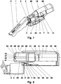
- FIG. 1 shows a dimetric representation of a hinge (1) with a device for damping and / or decelerating (10) and the FIG. 2 a partial longitudinal section of such a hinge (1) with a damping device (10).
- hinge (1) is a cup hinge (1). It has two hinge arms (2, 3), one of which (2), for example, in the furniture body and the other (3) is mounted in the hinged door of a piece of furniture.
- the two hinge arms (2, 3) are hinged together by means of two articulated levers (4, 5).
- the limited by the open and the closed end position swivel angle of the hinge (1) is in the embodiment 110 degrees.
- the one in the body the piece of furniture fastened hinge arm (2) is in the representation of FIG. 1 a mounting arm (2).
- the hinged on the door hinge arm (3) comprises a hinge cup (6) with a flange (8).
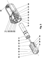
- the damping device (10) is in the FIG. 3 shown in an exploded view. It comprises a housing (20), a cylinder-piston unit (40) and a pressure piece (50). It is by means of a receptacle (32) which comprises a guide pin (33) and two guide surfaces (34, 35), centered on the hinge cup (6) and by means of a mounting flange (11), for example, outside of the hinge cup (6) in the pivotable door leaf of the furniture fixable.
- the damping device (10) can also be attached to the hinge (1).
- the damping device (10) has in the exemplary embodiment a maximum total length of 50 millimeters and a width in the region of the mounting flange (11) of 45 millimeters.
- the stroke of the pressure piece (50) relative to the housing (20) is for example 12 millimeters.
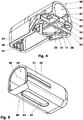
- housing (20) is an injection molded part, for example of a thermoplastic material. But it can also be made of aluminum or an aluminum alloy. It has a downwardly and to the front (22) open, semi-oval interior (21).
- the wall (23) of the interior (21) has two mutually opposite guide grooves (24). These borders on the front side (22). Their length is for example 25 millimeters and their height 1.3 millimeters.
- the guide grooves (24) are eg one millimeter deep.
- the distance between the opposing areas (26, 27) of the inner wall (23) is 12 millimeters in the exemplary embodiment.
- the closed rear wall (28) of the housing (20) has a pot-like receiving recess (29) oriented in the direction of the interior (21) and stiffening ribs (31).
- the housing (20) has a perforated bottom plate (38) which comprises the receptacle (32) including the molded, projecting from the housing (20) guide pin (33).
- the receptacle (32) formed here as a receiving channel (32) is arranged normal to the vertical center longitudinal plane of the device (10).
- the vertical center longitudinal plane is arranged normal to the support plane (15) and comprises the central axis (18).
- the receiving channel (32) is, measured in the direction of the central axis (18), for example, 6% longer than the edge (7) of the hinge cup (6), see. FIG. 2 , In the mounted state, the receiving channel (32) at least partially surrounds this edge (7).
- the guide pin (33) oriented, normal to the support plane (15) oriented inner surface of the receiving channel (32) is a guide surface (34).
- the guide pin (33) delimits the receiving channel (32) and is, for example, flush with the support plane (15) of the damping device (10).
- it has an at least approximately cuboid shape with a guide surface (35) oriented normal to the vertical center longitudinal plane of the device (10) and normal to the support plane.
- it can also have the shape of a cylinder with a circular, oval or elliptical cross-section.
- the guide surface (35) of the receiving (32) facing part of the lateral surface of the guide pin (33).
- At least the guide surface (35) of the guide pin (33) facing the rear wall (9) of the hinge cup (6) can also be formed obliquely so that the head cross-section of the guide pin (33) is smaller than the foot cross-section merging into the bottom plate (38).
- the two guide surfaces (34, 35) are at least approximately opposite oriented to each other. This means that their normal vectors point in opposite directions, whereby the single normal vector can deviate from this direction by an angle of up to 30 degrees.
- the length of the bottom plate (38) in the direction of the central axis (18) in the embodiment corresponds to half the length of the housing (20).
- the bottom plate (38) also comprises the mounting flange (11), which in the representations of Figures 3 and 4 has four through holes (13, 14).
- Two through holes (13) are in extension of the receiving channel (32), the other two through holes (14) are, for example in the longitudinal direction of the damping device (10) offset outside this channel (32).
- the through holes (13) serve as material reduction.
- the damping device (10) can also be fastened to the hinge (1) or to the door leaf outside the hinge (1), for example by means of screws which are inserted into the through-bores (13). By means of two in the through holes (14) inserted screws, the damping device (10) can be attached to the piece of furniture.
- the pressure piece (50) is a one-sided open, pot-shaped component. It is in the FIG. 5 shown as a single part.
- the pressure piece (50) has, for example, a length oriented in the direction of the longitudinal axis (58) which, for example, corresponds to 95% of the length of the guide grooves (24). Its wall thickness is for example one millimeter.
- the lateral surface (51) of the pressure piece (50) has two longitudinally oriented guide rails (52) which adjoin the opening (53). The height of these guide rails (52) is for example 0.7 millimeters and their length is half the length of the pressure piece (50). With these guide rails (52) sits the pressure piece (50) in the guide grooves (24) of the housing (20).
- This large guide length prevents tilting of the pressure piece (50) in the housing (20).
- the vertical and the lateral play of the pressure piece (50) in the housing (20) for example, each 0.5 millimeters.
- a maximum inclination of the longitudinal axis (58) of the pressure piece (50) of 2.4 degrees with respect to the central axis (18) of the damping device (10) is possible.
- a slot (55) is arranged on the underside (54) of the pressure piece (50). Its length is in the exemplary embodiment four-thirds of the maximum stroke of the pressure piece (50).
- the slot (55) is e.g. four millimeters wide. When mounted, the slot (55) forms e.g. with a housing arranged in the stop pin (39) a stroke limitation.
- the opening (53) facing away from the end wall (56) in the embodiment has a central portion (57) which is arranged normal to the longitudinal axis (58) of the pressure piece (50). Above this section (57) includes, for example, by 22 degrees to this inclined portion (59), see. FIG. 2 , In the lower area, the end wall (56) has a bent portion (61). The end wall (56) may also be curved convexly one or two axes, have an inclined plane, etc.
- the inner wall (62) of the end wall (56) has a receiving recess (63).
- the cylinder-piston unit (40) comprises a cylinder (41) and a piston, which is connected to a protruding from the cylinder (41) piston rod (42).
- spring-loaded piston defines a displacement chamber from a compensation chamber.
- the cylinder (41) sits with radial play in the receiving recess (29).
- the piston rod (42) has radial clearance for receiving recess (63).
- the cylinder-piston unit (40) can also be installed in reverse in the damping device (10). For mounting the damping device (10), for example, first the cylinder-piston unit (40) is inserted into the housing (20). Thereafter, the pressure piece (50) is inserted and locked in the stop pin (39). The assembly can also be done in a different order.
- the damping device (10) thus consists of only three parts, namely the housing (20), the cylinder-piston unit (40) and the pressure piece (50). It is thus inexpensive to produce and assembled automatically without special tool. It is also conceivable to form the pressure piece (50) and the cylinder (41) of the cylinder-piston unit (40) as a common component. For example, then the slot (55) is an oval, in the direction of the longitudinal axis (58) oriented recess of the cylinder jacket. The piston rod (42) is mounted in the housing (20) in this embodiment. This damping device (20) then consists of only two parts.
- the mounted damping device (10) can be placed with the support plane (15), for example on the door leaf.
- the damping device (10) by means of the guide surface (34) of the receptacle (32) at the edge (7) of the hinge cup (6) is aligned.
- the guide pin (33) engages in the hinge cup (6).
- the guide surface (35) of the guide pin (33) can rest on the rear wall (9) of the hinge cup (6) or, for example, have a distance of, for example, up to one millimeter from it.
- the Guide pin (33) is thus a centering pin (33), with which the position of the damping device (10) is fixed relative to the hinge (1).
- a displacement or pivoting of the damping device (10) relative to the hinge (1) is - except for the position tolerance - prevented.
- the receptacle (32) thus engages around the edge (7) of the hinge cup (6) with the guide surfaces (34, 35) delimiting them on several sides.
- the damping device (10) is fastened to the door leaf, for example, by means of screws which project through the through-bores (14).
- the two hinge arms (2, 3) pivot relative to each other.
- the pressure piece (50) approaches the mounting arm (2).
- the pressure piece (50) touches the mounting arm (2) or the outer articulated lever (4), it is inserted. It slides on the mounting arm (2) or the outer articulated lever (4).
- the pressure piece (50) pushes in the adjoining the closed end position of the hinge (1) pivot angle, the piston rod (42) with the piston.
- the slot (55) moves relative to the stop pin (39).
- the guide (24, 52) absorbs the lateral force components, so that the cylinder-piston unit (40) is loaded in only one direction parallel to the piston rod (42).
- the piston rod seal thus experiences no lateral forces that could cause leaks in the cylinder-piston unit (40).
- hydraulic or pneumatic medium is displaced throttled and delays the speed of the door leaf. For example, the higher the pan angular velocity, the greater the delay.
- the force transmitted to the cylinder-piston unit (40) is directed to the housing (20) and derived from the latter via the mounting flange (11) in the furniture door.
- the pressure piece (50) from the mounting arm (2) or the outer hinge lever (4) dissolves.
- the spring disposed in the cylinder (41) pushes the piston outward with the piston rod (42) and the pressure piece (50).
- the slot (55) in this case migrates along the stop pin (39) until its rear edge (64) abuts the stop pin (39).
- the stop pin (39) now prevents further extension of the pressure piece (50). It thus forms a stop for the extended position of the damping device (10).
- the damping device (10) can be arranged on all cup hinges (1) whose edge (7) in the direction of the central axis (18) is shorter than the length of the receptacle (32) measured in this direction.
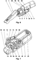
- the FIG. 6 shows a further embodiment of a hinge (1) with a damping device (10).
- the hinge cup (6) has, for example, a rear wall (9) with a recess.
- the damping device (10) has two centering pins (33, 36) which are arranged laterally of the frontal opening (25) of the housing (20). For example, they stand out in the direction of the end wall (56) of the pressure piece (50) by three millimeters.
- the length of the centering pins (33, 36) normal to the support plane (15) corresponds to the length of the centering pins (33) in the first embodiment.
- FIG. 7 is a bottom-dimensional view of a damping device (10) with a receptacle (32) with two eccentric centering pins (33, 36) shown.
- the cylinder-piston unit (40) is mounted in the housing (20).
- the piston rod (42) is mounted in the pressure piece (50), as in the FIG. 2 shown.
- the pressure piece (50) is displaceably mounted in guide grooves (24) of the housing (20) in the direction of the central axis (18). On its underside (54) has the pressure piece (50) has a slot (55) into which a in the housing (20) integrated stop pin (39) engages.
- the mounting flange (11) of the damping device (10) has four through holes (13; 14), of which two (13) in the receiving channel (32) and the other two (14) outside the receiving channel (32) are arranged.
- the assembly and assembly of the damping device (10) takes place as described above.
- the damping device (10) is door leaf side e.g. arranged on the cup hinge (1).
- the receptacle (32) and the centering pins (33) engage around the edge (7) of the hinge cup (6) adjoining the rear wall (9) in a form-fitting manner.
- the damping device (10) without adjustment work on the hinge (1) can be recognized.
- This damping device (10) can thus be used for cup hinges (1), the mounting arm (2) in the pivoted state of the hinge (1) fills the length of the hinge cup (6) in the direction of the central axis (18) to more than 90%.
- this damping device (10) can also be used for other types of cup hinges (1).
- the receptacle (32) engages outside the edge (7) of the hinge cup (6).
- it then comprises, for example, three guide surfaces, one of which is arranged, for example, like the guide surface (34) in the first exemplary embodiment.
- the two others Guiding surfaces are then arranged opposite one another on the edge regions oriented in the longitudinal direction of the hinge (1).
- a delay device upon the actuation of which, for example, air is displaced from the displacement space into the environment.
- the provision of the delay device is effected for example by means of a spring.
- the device for damping and / or decelerating (10) may also be at the open end position of two relatively moving parts, e.g. be arranged a sliding or pivoting door.
Landscapes
- Hinges (AREA)
Description
- Die Erfindung betrifft eine Vorrichtung zum Dämpfen und/oder Verzögern mit einem Gehäuse, mit einem im Gehäuse geführten Druckstück und mit einer im Gehäuse und im Druckstück angeordneten, einen Zylinder und einen Kolben umfassenden Zylinder-Kolbeneinheit, die einen als Teil des Gehäuses ausgebildeten Befestigungsflansch mit einer Auflagefläche und mit mindestens zwei Durchbrüchen aufweist.
- Aus der
WO 2005/088052 A1 und derEP 1 907 657 A1 sind auf einen Scharniertopf aufsetzbare Dämpfungsvorrichtungen bekannt. Mittels zweier Schrauben werden der Scharniertopf und die Dämpfungsvorrichtung gemeinsam z.B. an der Tür eines Möbelstücks befestigt. Bei einer nachträglichen Montage der Dämpfungsvorrichtung müssen entweder die Befestigungsschrauben des Scharniertopfs gelöst werden oder es müssen zusätzliche Bohrungen in den Scharniertopfflansch eingebracht werden. - Der vorliegenden Erfindung liegt die Problemstellung zugrunde, eine nachträglich montierbare Dämpfungsvorrichtung zu entwickeln, die schnell und genau an verschiedene Scharnierbauformen angeordnet werden kann.
- Diese Problemstellung wird mit den Merkmalen des Hauptanspruches gelöst. Dazu ist das Druckstück entweder topfförmig und einseitig offen ausgebildet und die Zylinder-Kolben-Einheit hat radiales Spiel zum Druckstück oder das Druckstück ist mit dem Zylinder der Zylinder-Kolben-Einheit als gemeinsames Bauteil ausgebildet. Der Befestigungsflansch umfasst mindestens zwei zumindest annähernd normal zur Auflagefläche orientierte, voneinander beabstandete Leitflächen. Die Leitflächen begrenzen mehrseitig eine an einem Scharniertopf zentrierbare Aufnahme, wobei beide Leitflächen zumindest annähernd entgegengesetzt zueinander orientierte Innenflächen der Aufnahme sind. Zumindest eine Leitfläche ist an einem am Gehäuse angeformten und von diesem abstehenden, in den Scharniertopf eintauchbaren Zentrierzapfen angeordnet. Außerdem sind mindestens zwei Durchbrüche außerhalb der Aufnahme angeordnet und durchdringen die Auflagefläche, sodass die Vorrichtung mittels Befestigungsmitteln außerhalb eines den Scharniertopf aufweisenden Scharniers an einem Möbelstück befestigbar ist.
- Weitere Einzelheiten der Erfindung ergeben sich aus den Unteransprüchen und der nachfolgenden Beschreibung schematisch dargestellter erfindungsgemäßer Ausführungsformen.
- Figur 1:
- Scharnier mit Dämpfungsvorrichtung;
- Figur 2:
- Teillängsschnitt von
Figur 1 ; - Figur 3:
- Explosionszeichnung einer Dämpfungsvorrichtung;
- Figur 4:
- Gehäuse;
- Figur 5:
- Druckstück;
- Figur 6:
- Scharnier mit zwei Zentrierzapfen;
- Figur 7:
- Unteransicht einer Dämpfungsvorrichtung mit zwei Zentrierzapfen.
- Die
Figur 1 zeigt eine dimetrische Darstellung eines Scharniers (1) mit einer Vorrichtung zum Dämpfen und/oder Verzögern (10) und dieFigur 2 einen Teillängsschnitt eines derartigen Scharniers (1) mit einer Dämpfungsvorrichtung (10). - Das in den
Figuren 1 und 2 dargestellte Scharnier (1) ist ein Topfscharnier (1). Es hat zwei Scharnierarme (2, 3), von denen einer (2) z.B. im Möbelkorpus und der andere (3) in der schwenkbaren Tür eines Möbelstücks befestigt ist. Die beiden Scharnierarme (2, 3) sind mittels zweier Gelenkhebel (4, 5) miteinander gelenkig verbunden. Der durch die offene und die geschlossene Endlage begrenzte Schwenkwinkel des Scharniers (1) beträgt im Ausführungsbeispiel 110 Grad. Der im Korpus des Möbelstücks befestigbare Scharnierarm (2) ist in der Darstellung derFigur 1 ein Montagearm (2). Der an der Tür befestigbare Scharnierarm (3) umfasst einen Scharniertopf (6) mit einem Flansch (8). - Die Dämpfungsvorrichtung (10) ist in der
Figur 3 in einer Explosionszeichnung dargestellt. Sie umfasst ein Gehäuse (20), eine Zylinder-Kolben-Einheit (40) und ein Druckstück (50). Sie ist mittels einer Aufnahme (32), die einen Leitzapfen (33) und zwei Leitflächen (34, 35) umfasst, am Scharniertopf (6) zentriert und mittels eines Befestigungsflansches (11) z.B. außerhalb des Scharniertopfs (6) im schwenkbaren Türblatt des Möbelstücks befestigbar. Die Dämpfungsvorrichtung (10) kann jedoch auch am Scharnier (1) befestigt sein. - Die Dämpfungsvorrichtung (10) hat im Ausführungsbeispiel eine maximale Gesamtlänge von 50 Millimetern und eine Breite im Bereich des Befestigungsflansches (11) von 45 Millimetern. Der Hub des Druckstücks (50) relativ zum Gehäuse (20) beträgt beispielsweise 12 Millimeter.
- Das in der
Figur 4 als Einzelteil dargestellte Gehäuse (20) ist ein Spritzgussteil, z.B. aus einem thermoplastischen Werkstoff. Es kann aber auch aus Aluminium oder einer Aluminiumlegierung hergestellt sein. Es hat einen nach unten und zur Vorderseite (22) hin offenen, halbovalen Innenraum (21). Die Wandung (23) des Innenraums (21) weist zwei einander gegenüber liegende Führungsnuten (24) auf. Diese grenzen an die Vorderseite (22) an. Ihre Länge beträgt z.B. 25 Millimeter und ihre Höhe 1,3 Millimeter. Die Führungsnuten (24) sind z.B. einen Millimeter tief. Der Abstand der einander gegenüber liegenden Bereiche (26, 27) der Innenwandung (23) beträgt im Ausführungsbeispiel 12 Millimeter. - Die geschlossene Rückwand (28) des Gehäuses (20) hat eine in Richtung des Innenraums (21) orientierte topfartige Aufnahmeeinsenkung (29) sowie Versteifungsrippen (31).
- Das Gehäuse (20) hat eine durchbrochene Bodenplatte (38), die die Aufnahme (32) einschließlich des angeformten, vom Gehäuse (20) abstehenden Leitzapfens (33) umfasst. Die hier als Aufnahmerinne (32) ausgebildete Aufnahme (32) ist normal zur vertikalen Mittenlängsebene der Vorrichtung (10) angeordnet. Die vertikale Mittenlängsebene ist normal zur Auflageebene (15) angeordnet und umfasst die Mittelachse (18). Die Aufnahmerinne (32) ist, in der Richtung der Mittelachse (18) gemessen, z.B. um 6 % länger als der Rand (7) des Scharniertopfs (6), vgl.
Figur 2 . Im montierten Zustand umgreift die Aufnahmerinne (32) zumindest bereichsweise diesen Rand (7). Die zum Leitzapfen (33) orientierte, normal zur Auflageebene (15) orientierte Innenfläche der Aufnahmerinne (32) ist eine Leitfläche (34). - Der Leitzapfen (33) begrenzt die Aufnahmerinne (32) und ist beispielsweise bündig mit der Auflageebene (15) der Dämpfungsvorrichtung (10). Im Ausführungsbeispiel hat er eine zumindest annähernd quaderförmige Gestalt mit einer normal zur vertikalen Mittenlängsebene der Vorrichtung (10) und normal zur Auflageebene orientierten Leitfläche (35). Er kann aber auch die Gestalt eines Zylinders mit kreisförmigem, ovalem oder elliptischem Querschnitt haben. Bei einer derartigen Ausführungsform ist die Leitfläche (35) der der Aufnahme (32) zugewandte Teil der Mantelfläche des Leitzapfens (33). Zumindest die der Rückwand (9) des Scharniertopfs (6) zugewandte Leitfläche (35) des Leitzapfens (33) kann auch schräg ausgebildet sein, so dass der Kopfquerschnitt des Leitzapfens (33) kleiner ist als der in die Bodenplatte (38) übergehende Fußquerschnitt. Die beiden Leitflächen (34, 35) sind zumindest annähernd entgegengesetzt zueinander orientiert. Dies bedeutet, dass ihre Normalenvektoren in entgegengesetzte Richtungen zeigen, wobei der einzelne Normalenvektor um einen Winkel von bis zu 30 Grad von dieser Richtung abweichen kann.
- Die Länge der Bodenplatte (38) in Richtung der Mittelachse (18) entspricht im Ausführungsbeispiel der Hälfte der Länge des Gehäuses (20). Die Bodenplatte (38) umfasst außerdem den Befestigungsflansch (11), der in den Darstellungen der
Figuren 3 und4 vier Durchgangsbohrungen (13, 14) aufweist. Zwei Durchgangsbohrungen (13) liegen in Verlängerung der Aufnahmerinne (32), die anderen beiden Durchgangsbohrungen (14) liegen z.B. in Längsrichtung der Dämpfungsvorrichtung (10) versetzt außerhalb dieser Rinne (32). Die Durchgangsbohrungen (13) dienen z.B. der Materialreduzierung. Die Dämpfungsvorrichtung (10) kann aber auch z.B. mittels Schrauben, die in die Durchgangsbohrungen (13) eingesetzt werden, am Scharnier (1) oder am Türblatt außerhalb des Scharniers (1) befestigt werden. Mittels zweier in die Durchgangsbohrungen (14) eingesetzter Schrauben kann die Dämpfungsvorrichtung (10) am Möbelstück befestigt werden. - Das Druckstück (50) ist ein einseitiges offenes, topfförmiges Bauteil. Es ist in der
Figur 5 als Einzelteil dargestellt. Das Druckstück (50) hat beispielsweise eine in Richtung der Längsachse (58) orientierte Länge, die z.B. 95 % der Länge der Führungsnuten (24) entspricht. Seine Wandstärke beträgt beispielsweise ein Millimeter. Die Mantelfläche (51) des Druckstücks (50) weist zwei in der Längsrichtung orientierte Führungsschienen (52) auf, die an die Öffnung (53) angrenzen. Die Höhe dieser Führungsschienen (52) beträgt beispielsweise 0,7 Millimeter und ihre Länge die Hälfte der Länge des Druckstücks (50). Mit diesen Führungsschienen (52) sitzt das Druckstück (50) in den Führungsnuten (24) des Gehäuses (20). Aufgrund dieser großen Führungslänge wird ein Verkanten des Druckstücks (50) im Gehäuse (20) verhindert. Das Vertikal- und das Lateralspiel des Druckstücks (50) im Gehäuse (20) betragen z.B. jeweils 0,5 Millimeter. Hiermit ist beispielsweise eine maximale Schiefstellung der Längsachse (58) des Druckstücks (50) von 2,4 Grad gegenüber der Mittelachse (18) der Dämpfungsvorrichtung (10) möglich. - An der Unterseite (54) des Druckstücks (50) ist ein Langloch (55) angeordnet. Seine Länge beträgt im Ausführungsbeispiel vier Drittel des maximalen Hubs des Druckstücks (50). Das Langloch (55) ist z.B. vier Millimeter breit. Im montierten Zustand bildet das Langloch (55) z.B. mit einem im Gehäuse angeordneten Anschlagzapfen (39) eine Hubbegrenzung.
- Die der Öffnung (53) abgewandte Stirnwand (56) hat im Ausführungsbeispiel einen zentralen Abschnitt (57), der normal zur Längsachse (58) des Druckstücks (50) angeordnet ist. Oberhalb dieses Abschnitts (57) schließt ein z.B. um 22 Grad zu diesem geneigter Abschnitt (59) an, vgl.
Figur 2 . Im unteren Bereich hat die Stirnwand (56) einen gebogenen Abschnitt (61). Die Stirnwand (56) kann auch konvex ein- oder zweiachsig gekrümmt sein, eine schräge Ebene aufweisen, etc. Die Innenwandung (62) der Stirnwand (56) hat eine Aufnahmeeinsenkung (63). - Die Aufnahmeeinsenkung (29) des Gehäuses (20) und die Aufnahmeeinsenkung (63) des Druckstücks (50) tragen die Zylinder-Kolben-Einheit (40). Die Zylinder-Kolben-Einheit (40) umfasst einen Zylinder (41) und einen Kolben, der mit einer aus dem Zylinder (41) herausstehenden Kolbenstange (42) verbunden ist. In dem beispielweise mit Öl befüllten Zylinder (41) grenzt der z.B. mit Drosselventilen versehene, federbelastete Kolben einen Verdrängungsraum von einem Ausgleichsraum ab. Der Zylinder (41) sitzt mit radialem Spiel in der Aufnahmeeinsenkung (29). Die Kolbenstange (42) hat radiales Spiel zur Aufnahmeeinsenkung (63). Das radiale Spiel der Zylinder-KolbenEinheit (40) zum Gehäuse (20) und zum Druckstück (50) ist beispielsweise größer als das Spiel des Druckstücks (50) relativ zum Gehäuse (20). Die Zylinder-Kolben-Einheit (40) kann auch umgekehrt in die Dämpfungsvorrichtung (10) eingebaut sein. Zur Montage der Dämpfungsvorrichtung (10) wird z.B. zunächst die Zylinder-Kolben-Einheit (40) in das Gehäuse (20) eingesetzt. Danach wird das Druckstück (50) eingesetzt und im Anschlagzapfen (39) verrastet. Die Montage kann auch in anderer Reihenfolge erfolgen.
- Die Dämpfungsvorrichtung (10) besteht somit nur aus drei Teilen, nämlich dem Gehäuse (20), der Zylinder-Kolben-Einheit (40) und dem Druckstück (50). Sie ist damit kostengünstig herstellbar und ohne Spezialwerkzeug automatisiert montierbar. Es ist auch denkbar, das Druckstück (50) und den Zylinder (41) der Zylinder-Kolben-Einheit (40) als gemeinsames Bauteil auszubilden. Beispielsweise ist dann das Langloch (55) eine ovale, in Richtung der Längsachse (58) orientierte Ausnehmung des Zylindermantels. Die Kolbenstange (42) ist in dieser Ausführungsform im Gehäuse (20) gelagert. Diese Dämpfungsvorrichtung (20) besteht dann nur aus zwei Teilen.
- Die montierte Dämpfungsvorrichtung (10) kann mit der Auflageebene (15) z.B. auf das Türblatt aufgesetzt werden. Hierbei wird die Dämpfungsvorrichtung (10) mittels der Leitfläche (34) der Aufnahme (32) am Rand (7) des Scharniertopfs (6) ausgerichtet. Außerdem greift der Leitzapfen (33) in den Scharniertopf (6) ein. Die Leitfläche (35) des Leitzapfens (33) kann an der Rückwand (9) des Scharniertopfs (6) anliegen oder z.B. von ihr einen Abstand von z.B. bis zu einem Millimeter haben. Der Leitzapfen (33) ist damit ein Zentrierzapfen (33), mit dem die Lage der Dämpfungsvorrichtung (10) relativ zum Scharnier (1) festgelegt wird. Ein Verschieben oder Verschwenken der Dämpfungsvorrichtung (10) relativ zum Scharnier (1) wird - bis auf die Lagetoleranz - verhindert. Die Aufnahme (32) umgreift damit mit den sie mehrseitig begrenzenden Leitflächen (34, 35) den Rand (7) des Scharniertopfs (6). Die Dämpfungsvorrichtung (10) wird beispielsweise mittels Schrauben, die durch die Durchgangsbohrungen (14) hindurchragen, am Türblatt befestigt.
- Beim Schließen der Möbeltür schwenken die beiden Scharnierarme (2, 3) relativ zueinander. Das Druckstück (50) nähert sich dem Montagearm (2). Sobald das Druckstück (50) den Montagearm (2) oder den äußeren Gelenkhebel (4) berührt, wird es eingeschoben. Es gleitet hierbei auf dem Montagearm (2) oder dem äußeren Gelenkhebel (4) ab. Das Druckstück (50) schiebt in dem an die geschlossene Endlage des Scharniers (1) angrenzenden Schwenkwinkel die Kolbenstange (42) mit dem Kolben ein. Hierbei wandert das Langloch (55) relativ zum Anschlagzapfen (39). Bei einem gegebenenfalls außermittigen Kraftangriff nimmt die Führung (24, 52) die Querkraftkomponenten auf, so dass die Zylinder-Kolben-Einheit (40) nur in einer Richtung parallel zur Kolbenstange (42) belastet wird. Die Kolbenstangendichtung erfährt somit keine Querkräfte, die Undichtigkeiten der Zylinder-Kolben-Einheit (40) verursachen könnten. Beim Einfahren des Kolbens wird z.B. hydraulisches oder pneumatisches Medium gedrosselt verdrängt und die Geschwindigkeit des Türblatts verzögert. Diese Verzögerung ist beispielsweise umso größer, je höher die Schwenk-Winkelgeschwindigkeit ist. Die auf die Zylinder-Kolben-Einheit (40) übertragene Kraft wird auf das Gehäuse (20) geleitet und von diesem über den Befestigungsflansch (11) in die Möbeltür abgeleitet.
- Beim Öffnen der Tür löst sich das Druckstück (50) vom Montagearm (2) oder vom äußeren Gelenkhebel (4). Beispielsweise drückt die im Zylinder (41) angeordnete Feder den Kolben mit der Kolbenstange (42) und dem Druckstück (50) nach außen. Das Langloch (55) wandert hierbei entlang des Anschlagzapfens (39), bis seine hintere Kante (64) am Anschlagzapfen (39) anschlägt. Der Anschlagzapfen (39) verhindert nun ein weiteres Ausfahren des Druckstücks (50). Er bildet damit einen Anschlag für die ausgefahrene Stellung der Dämpfungsvorrichtung (10).
- Die Dämpfungsvorrichtung (10) kann an allen Topfscharnieren (1) angeordnet werden, deren Rand (7) in Richtung der Mittelachse (18) kürzer ist als die in dieser Richtung gemessene Länge der Aufnahme (32).
- Die
Figur 6 zeigt eine weitere Ausführungsform eines Scharniers (1) mit einer Dämpfungsvorrichtung (10). Der Scharniertopf (6) hat beispielsweise eine Rückwand (9) mit einer Aussparung. Die Dämpfungsvorrichtung (10) hat zwei Zentrierzapfen (33, 36), die seitlich der stirnseitigen Öffnung (25) des Gehäuses (20) angeordnet sind. Beispielsweise stehen sie in Richtung der Stirnwand (56) des Druckstücks (50) um drei Millimeter heraus. Die Länge der Zentrierzapfen (33, 36) normal zur Auflageebene (15) entspricht der Länge der Zentrierzapfen (33) im ersten Ausführungsbeispiel. - In der
Figur 7 ist eine dimetrische Unteransicht einer Dämpfungsvorrichtung (10) mit einer Aufnahme (32) mit zwei außermittigen Zentrierzapfen (33, 36) dargestellt. Im Gehäuse (20) ist die Zylinder-Kolben-Einheit (40) gelagert. Hierbei liegt der Zylinder (41) mit radialem Spiel in der Aufnahmeeinsenkung (29). Die Kolbenstange (42) ist im Druckstück (50) gelagert, wie in derFigur 2 dargestellt. - Das Druckstück (50) ist in Führungsnuten (24) des Gehäuses (20) in Richtung der Mittelachse (18) verschiebbar gelagert. An seiner Unterseite (54) hat das Druckstück (50) ein Langloch (55), in das ein in das Gehäuse (20) integrierter Anschlagzapfen (39) eingreift.
- Der Befestigungsflansch (11) der Dämpfungsvorrichtung (10) hat vier Durchgangsbohrungen (13; 14), von denen jeweils zwei (13) in der Aufnahmerinne (32) und die zwei anderen (14) außerhalb der Aufnahmerinne (32) angeordnet sind.
- Der Zusammenbau und die Montage der Dämpfungsvorrichtung (10) erfolgt wie oben beschrieben. Nach der Montage ist die Dämpfungsvorrichtung (10) türblattseitig z.B. am Topfscharnier (1) angeordnet.
- Die Aufnahme (32) und die Zentrierzapfen (33) umgreifen den an die Rückwand (9) angrenzenden Rand (7) des Scharniertopfs (6) formschlüssig. Somit kann die Dämpfungsvorrichtung (10) ohne Anpassarbeiten an das Scharnier (1) angesetzt werden. Im Ausführungsbeispiel liegen die beiden Zentrierzapfen (33, 36) nach der Montage im äußeren Bereich des Scharniertopfs (6). Diese Dämpfungsvorrichtung (10) kann somit für Topfscharniere (1) eingesetzt werden, deren Montagearm (2) im eingeschwenkten Zustand des Scharniers (1) die Länge des Scharniertopfs (6) in Richtung der Mittelachse (18) zu mehr als 90 % ausfüllt. Natürlich kann diese Dämpfungsvorrichtung (10) auch für andere Bauformen von Topfscharnieren (1) eingesetzt werden.
- Die Aufnahme (32) umgreift außen den Rand (7) des Scharniertopfs (6). Hierzu umfasst sie dann z.B. drei Leitflächen, von denen eine beispielsweise wie die Leitfläche (34) im ersten Ausführungsbeispiel angeordnet ist. Die beiden anderen Leitflächen sind dann einander gegenüber an den in Längsrichtung des Scharniers (1) orientierten Randbereichen angeordnet.
- Anstatt der beschriebenen Vorrichtung (10) kann auch eine Verzögerungsvorrichtung eingesetzt werden, bei deren Betätigung beispielsweise Luft aus dem Verdrängungsraum in die Umgebung verdrängt wird. Die Rückstellung der Verzögerungsvorrichtung erfolgt beispielsweise mittels einer Feder.
- Die Vorrichtung zum Dämpfen und/oder Verzögern (10) kann auch an der geöffneten Endlage zweier relativ zueinander bewegter Teile, z.B. einer Schiebe- oder Schwenktür angeordnet sein.
- Auch Kombinationen der verschiedenen Ausführungsbeispiele sind denkbar.
-
- 1
- Scharnier, Topfscharnier
- 2
- Scharnierarm, Montagearm
- 3
- Scharnierarm
- 4
- äußerer Gelenkhebel
- 5
- innerer Gelenkhebel
- 6
- Scharniertopf
- 7
- Rand von (6)
- 8
- Flansch
- 9
- Rückwand
- 10
- Vorrichtung zum Dämpfen und/oder Verzögern, Dämpfungsvorrichtung
- 11
- Befestigungsflansch
- 13
- Durchgangsbohrungen
- 14
- Durchgangsbohrungen
- 15
- Auflagefläche, eben
- 18
- Mittelachse
- 20
- Gehäuse
- 21
- Innenraum
- 22
- Vorderseite
- 23
- Wandung, Innenwandung
- 24
- Führungsnuten
- 25
- Öffnung
- 26
- Bereich von (23)
- 27
- Bereich von (23)
- 28
- Rückwand
- 29
- Aufnahmeeinsenkung
- 31
- Versteifungsrippen
- 32
- Aufnahme, Aufnahmerinne
- 33
- Leitzapfen, Zentrierzapfen
- 34
- Leitfläche
- 35
- Leitfläche
- 36
- Leitzapfen, Zentrierzapfen
- 38
- Bodenplatte
- 39
- Anschlagzapfen
- 40
- Zylinder-Kolben-Einheit
- 41
- Zylinder
- 42
- Kolbenstange
- 50
- Druckstück
- 51
- Mantelfläche
- 52
- Führungsschienen
- 53
- Öffnung
- 54
- Unterseite
- 55
- Langloch
- 56
- Stirnwand
- 57
- zentraler Abschnitt
- 58
- Längsachse
- 59
- geneigter Abschnitt
- 61
- gebogener Abschnitt
- 62
- Innenwandung
- 63
- Aufnahmeeinsenkung
- 64
- hintere Kante von (55)
Claims (6)
- Vorrichtung zum Dämpfen und/oder Verzögern (10) mit einem Gehäuse (20), mit einem im Gehäuse (20) geführten Druckstück (50) und mit einer im Gehäuse (20) und im Druckstück (50) angeordneten, einen Zylinder (41) und einen Kolben umfassenden Zylinder-Kolbeneinheit (40), wobei die Vorrichtung einen als Teil des Gehäuses (20) ausgebildeten Befestigungsflansch (11) mit einer Auflagefläche (15) und mit mindestens zwei Durchbrüchen (13; 14) aufweist, wobei- das Druckstück (50) entweder topfförmig und einseitig offen ausgebildet ist und die Zylinder-Kolben-Einheit (40) radiales Spiel zum Druckstück (50) hat oder dass das Druckstück (50) mit dem Zylinder (41) der Zylinder-Kolben-Einheit (40) als gemeinsames Bauteil ausgebildet ist,- der Befestigungsflansch (11) mindestens zwei zumindest annähernd normal zur Auflagefläche (15) orientierte, voneinander beabstandete Leitflächen (34, 35) umfasst, und- die Leitflächen (34, 35) eine an einem Scharniertopf (6) zentrierbare Aufnahme (32) mehrseitig begrenzen, wobei beide Leitflächen (34, 35) zumindest annähernd entgegengesetzt zueinander orientierte Innenflächen der Aufnahme (32) sind, dadurch gekennzeichnet,- dass die Aufnahme (32) vorgesehen ist, den Rand eines Scharniertopfs (6) zu umgreifen,- dass zumindest eine Leitfläche (35) an einem am Gehäuse (20) angeformten und von diesem abstehenden Zentrierzapfen (33) angeordnet ist, der im montierten Zustand in einen Scharniertopf (6) eingreifen kann, und- dass die mindestens zwei Durchbrüche (14) außerhalb der Aufnahme (32) angeordnet sind und die Auflagefläche (15) durchdringen, sodass die Vorrichtung (10) mittels Befestigungsmitteln außerhalb eines den Scharniertopf (6) aufweisenden Scharniers (1) an einem Möbelstück befestigbar ist.
- Vorrichtung (10) nach Anspruch 1, dadurch gekennzeichnet, dass die Aufnahme (32) zwei zueinander beabstandete Zentrierzapfen (33, 36) umfasst.
- Scharnier (1) mit einem Scharniertopf (6) und mit einer Vorrichtung (10) nach Anspruch 1, dadurch gekennzeichnet, dass alle Zentrierzapfen (33, 36) in den Scharniertopf (6) eingreifen.
- Scharnier (1) nach Anspruch 3, dadurch gekennzeichnet, dass die Aufnahme (32) den Rand (7) des Scharniertopfs (6) umgreift.
- Möbelstück mit einem Scharnier (1) nach Anspruch 3, dadurch gekennzeichnet, dass das Scharnier (1) den Korpus und ein relativ hierzu schwenkbares Türblatt verbindet.
- Möbelstück nach Anspruch 5, dadurch gekennzeichnet, dass die Vorrichtung zum Dämpfen und/oder Verzögern (10) mittels die Durchbrüche (14) durchdringenden Befestigungsmitteln am Türblatt befestigt ist.
Applications Claiming Priority (2)
| Application Number | Priority Date | Filing Date | Title |
|---|---|---|---|
| DE102009039559A DE102009039559A1 (de) | 2009-09-01 | 2009-09-01 | Vorrichtung zum Dämpfen und/oder Verzögern |
| PCT/DE2010/001012 WO2011026466A1 (de) | 2009-09-01 | 2010-08-30 | Vorrichtung zum dämpfen und/oder verzögern |
Publications (2)
| Publication Number | Publication Date |
|---|---|
| EP2473692A1 EP2473692A1 (de) | 2012-07-11 |
| EP2473692B1 true EP2473692B1 (de) | 2017-08-02 |
Family
ID=43302510
Family Applications (1)
| Application Number | Title | Priority Date | Filing Date |
|---|---|---|---|
| EP10766228.0A Not-in-force EP2473692B1 (de) | 2009-09-01 | 2010-08-30 | Vorrichtung zum dämpfen und/oder verzögern |
Country Status (6)
| Country | Link |
|---|---|
| US (1) | US8621713B2 (de) |
| EP (1) | EP2473692B1 (de) |
| JP (1) | JP5871799B2 (de) |
| CA (1) | CA2772673A1 (de) |
| DE (1) | DE102009039559A1 (de) |
| WO (1) | WO2011026466A1 (de) |
Families Citing this family (16)
| Publication number | Priority date | Publication date | Assignee | Title |
|---|---|---|---|---|
| DE102009039560A1 (de) * | 2009-09-01 | 2011-03-03 | Zimmer, Günther | Einstellbare Vorrichtung zum Dämpfen und/oder Verzögern |
| ITMI20131542A1 (it) * | 2013-09-19 | 2015-03-20 | Salice Arturo Spa | Cerniera decelerata per mobili |
| JP6677647B2 (ja) * | 2014-03-25 | 2020-04-08 | オーエル.エムアイ エス.アール.エル. | 流体的ヒンジ、具体的にはドア用の隠れヒンジ |
| US9163447B1 (en) * | 2014-09-18 | 2015-10-20 | King Slide Works Co., Ltd. | Hinge with damping device |
| DE102015106919A1 (de) * | 2015-05-04 | 2016-11-10 | Samet Kalip Ve Maden Esya San. Ve Tic. A.S. | Möbelscharnier mit einem Dämpfer |
| US9523227B1 (en) * | 2015-07-30 | 2016-12-20 | Nan Juen International Co., Ltd. | Anti-drop safety device assembly |
| TWI555487B (zh) * | 2015-11-26 | 2016-11-01 | 川湖科技股份有限公司 | 鉸鏈及其緩衝裝置 |
| TWI597432B (zh) * | 2015-11-26 | 2017-09-01 | 川湖科技股份有限公司 | 鉸鏈及其緩衝裝置 |
| US9874049B1 (en) * | 2016-08-11 | 2018-01-23 | Hardware Resources, Inc. | Compact hinge apparatus and method of use |
| EP3650728B1 (de) * | 2018-10-12 | 2024-11-06 | BSH Hausgeräte GmbH | Dämpfungseinheit und haushaltsgerät mit der dämpfungseinheit |
| US10947766B2 (en) * | 2019-05-07 | 2021-03-16 | B/E Aerospace, Inc. | Dampening hinges and table assemblies including the same |
| DE102019113335A1 (de) * | 2019-05-20 | 2020-11-26 | Samet Kalip Ve Maden Esya San. Ve Tic. A.S. | Möbelbeschlag |
| CN111719976B (zh) * | 2019-06-20 | 2025-03-28 | 广东精诺五金实业有限公司 | 一种阻尼器承载座及缓冲铰链 |
| GB2602285A (en) * | 2020-12-22 | 2022-06-29 | Titus D O O Dekani | Hinge Assembly |
| US11920401B2 (en) | 2021-05-03 | 2024-03-05 | Kohler Co. | Slow close mechanism for sliding applications |
| EP4450744A3 (de) * | 2023-04-20 | 2024-12-04 | LG Electronics Inc. | Kühlschrank |
Family Cites Families (11)
| Publication number | Priority date | Publication date | Assignee | Title |
|---|---|---|---|---|
| IT250443Y1 (it) * | 2000-09-19 | 2003-09-10 | Salice Arturo Spa | Dispositivo per la chiusura decelerata di parti di mobile scorrevoli |
| DE20115250U1 (de) * | 2001-07-06 | 2002-11-14 | Lautenschlaeger Mepla Werke | Dämpfungsvorrichtung |
| TWI231344B (en) * | 2004-02-24 | 2005-04-21 | Lushridge Inc | Fastening structure of buffering rod |
| DE202004011636U1 (de) * | 2004-03-12 | 2004-09-23 | MEPLA-WERKE LAUTENSCHLäGER GMBH & CO. KG | Dämpfungsvorrichtung für Möbelscharniere |
| SI21971A (sl) * | 2005-02-18 | 2006-08-31 | Lama D.D. Dekani | Oplemeniteni pohistveni sarnir |
| DE202005011752U1 (de) * | 2005-07-22 | 2006-11-30 | Hettich-Oni Gmbh & Co. Kg | Dämpfungselement |
| AT502486B1 (de) * | 2005-09-01 | 2007-04-15 | Blum Gmbh Julius | Anordnung mit einem scharnier, insbesondere möbelscharnier |
| WO2008020682A1 (en) * | 2006-08-18 | 2008-02-21 | Samsung Precision Industrial Co., Ltd | Door hinge device for absorbing the closing impact of furniture doors |
| JP3129172U (ja) * | 2006-11-24 | 2007-02-08 | 川湖科技股▲分▼有限公司 | 蝶番の緩衝装置 |
| CN201087643Y (zh) * | 2007-08-30 | 2008-07-16 | 伍志勇 | 家具铰链的缓冲装置 |
| US20130055528A1 (en) * | 2011-09-07 | 2013-03-07 | Mark Jeffrey Lowe | Detachable hinge damper |
-
2009
- 2009-09-01 DE DE102009039559A patent/DE102009039559A1/de not_active Withdrawn
-
2010
- 2010-08-30 WO PCT/DE2010/001012 patent/WO2011026466A1/de not_active Ceased
- 2010-08-30 EP EP10766228.0A patent/EP2473692B1/de not_active Not-in-force
- 2010-08-30 CA CA2772673A patent/CA2772673A1/en not_active Abandoned
- 2010-08-30 JP JP2012527203A patent/JP5871799B2/ja not_active Expired - Fee Related
-
2012
- 2012-02-29 US US13/407,862 patent/US8621713B2/en not_active Expired - Fee Related
Non-Patent Citations (1)
| Title |
|---|
| None * |
Also Published As
| Publication number | Publication date |
|---|---|
| JP5871799B2 (ja) | 2016-03-01 |
| EP2473692A1 (de) | 2012-07-11 |
| CA2772673A1 (en) | 2011-03-10 |
| JP2013503988A (ja) | 2013-02-04 |
| US20120180262A1 (en) | 2012-07-19 |
| DE102009039559A1 (de) | 2011-03-10 |
| US8621713B2 (en) | 2014-01-07 |
| WO2011026466A1 (de) | 2011-03-10 |
Similar Documents
| Publication | Publication Date | Title |
|---|---|---|
| EP2473692B1 (de) | Vorrichtung zum dämpfen und/oder verzögern | |
| EP2473693B1 (de) | Einstellbare vorrichtung zum dämpfen und/oder verzögern | |
| DE10254375C1 (de) | Vorrichtung zum Dämpfen von Schwenkbewegungen | |
| DE102006058639B4 (de) | Kombinierte Verzögerungs- und Beschleunigungsvorrichtung | |
| EP2247812B1 (de) | Beschleunigungs- und verzögerungsvorrichtung mit zwei mitnahmeelementen | |
| EP1404938B2 (de) | Dämpfungsvorrichtung | |
| EP2013434B1 (de) | Führungssystem mit beschleunigungs- und verzögerungsvorrichtung | |
| EP2411612B1 (de) | Möbelscharnier | |
| EP2841668B1 (de) | Schlepptürbeschlag | |
| AT506756B1 (de) | Möbelscharnier | |
| EP1725727B1 (de) | Dämpfungsvorrichtung für möbelscharniere | |
| EP3494270B1 (de) | Dämpfereinrichtung | |
| EP3070251B1 (de) | Beschleunigungs- und verzögerungsvorrichtung mit geräuscharmer bewegung | |
| DE102017126367A1 (de) | Klappenbeschlag für ein Möbel, Seitenwand eines Möbelkorpus und Möbel mit einer Seitenwand | |
| EP2796650A1 (de) | Möbelscharnier | |
| DE202004021727U1 (de) | Scharnier | |
| EP3581746B1 (de) | Kombinierte dämpfungs- und zuziehvorrichtung für eine mitteltür | |
| EP4064935B1 (de) | Möbelelement | |
| EP2617336A2 (de) | Duschabtrennung | |
| EP3380693B1 (de) | Dämpferbaugruppe eines topfscharniers | |
| DE10227078B4 (de) | Vorrichtung zum Dämpfen von Schwenkbewegungen | |
| DE102009035682A1 (de) | Scharnier mit hydraulischer Dämpfungsvorrichtung | |
| EP2492427A2 (de) | Beschlagvorrichtung für ein bewegliches Möbelteil | |
| EP2949845B1 (de) | Verstellbares klappenlager | |
| EP3478917B1 (de) | Mitteltür-zuziehvorrichtung mit übertragungsschlitten |
Legal Events
| Date | Code | Title | Description |
|---|---|---|---|
| PUAI | Public reference made under article 153(3) epc to a published international application that has entered the european phase |
Free format text: ORIGINAL CODE: 0009012 |
|
| 17P | Request for examination filed |
Effective date: 20120320 |
|
| AK | Designated contracting states |
Kind code of ref document: A1 Designated state(s): AL AT BE BG CH CY CZ DE DK EE ES FI FR GB GR HR HU IE IS IT LI LT LU LV MC MK MT NL NO PL PT RO SE SI SK SM TR |
|
| DAX | Request for extension of the european patent (deleted) | ||
| 17Q | First examination report despatched |
Effective date: 20150226 |
|
| GRAP | Despatch of communication of intention to grant a patent |
Free format text: ORIGINAL CODE: EPIDOSNIGR1 |
|
| STAA | Information on the status of an ep patent application or granted ep patent |
Free format text: STATUS: GRANT OF PATENT IS INTENDED |
|
| INTG | Intention to grant announced |
Effective date: 20170314 |
|
| GRAS | Grant fee paid |
Free format text: ORIGINAL CODE: EPIDOSNIGR3 |
|
| GRAA | (expected) grant |
Free format text: ORIGINAL CODE: 0009210 |
|
| STAA | Information on the status of an ep patent application or granted ep patent |
Free format text: STATUS: THE PATENT HAS BEEN GRANTED |
|
| AK | Designated contracting states |
Kind code of ref document: B1 Designated state(s): AL AT BE BG CH CY CZ DE DK EE ES FI FR GB GR HR HU IE IS IT LI LT LU LV MC MK MT NL NO PL PT RO SE SI SK SM TR |
|
| REG | Reference to a national code |
Ref country code: GB Ref legal event code: FG4D Free format text: NOT ENGLISH |
|
| REG | Reference to a national code |
Ref country code: CH Ref legal event code: EP Ref country code: AT Ref legal event code: REF Ref document number: 914667 Country of ref document: AT Kind code of ref document: T Effective date: 20170815 |
|
| REG | Reference to a national code |
Ref country code: FR Ref legal event code: PLFP Year of fee payment: 8 |
|
| REG | Reference to a national code |
Ref country code: IE Ref legal event code: FG4D Free format text: LANGUAGE OF EP DOCUMENT: GERMAN |
|
| REG | Reference to a national code |
Ref country code: DE Ref legal event code: R096 Ref document number: 502010013950 Country of ref document: DE |
|
| PGFP | Annual fee paid to national office [announced via postgrant information from national office to epo] |
Ref country code: NL Payment date: 20170821 Year of fee payment: 8 |
|
| REG | Reference to a national code |
Ref country code: NL Ref legal event code: FP |
|
| PGFP | Annual fee paid to national office [announced via postgrant information from national office to epo] |
Ref country code: DE Payment date: 20170817 Year of fee payment: 8 Ref country code: FR Payment date: 20170822 Year of fee payment: 8 Ref country code: GB Payment date: 20170929 Year of fee payment: 8 |
|
| PGFP | Annual fee paid to national office [announced via postgrant information from national office to epo] |
Ref country code: TR Payment date: 20170925 Year of fee payment: 8 Ref country code: AT Payment date: 20170825 Year of fee payment: 8 |
|
| REG | Reference to a national code |
Ref country code: LT Ref legal event code: MG4D |
|
| PG25 | Lapsed in a contracting state [announced via postgrant information from national office to epo] |
Ref country code: HR Free format text: LAPSE BECAUSE OF FAILURE TO SUBMIT A TRANSLATION OF THE DESCRIPTION OR TO PAY THE FEE WITHIN THE PRESCRIBED TIME-LIMIT Effective date: 20170802 Ref country code: FI Free format text: LAPSE BECAUSE OF FAILURE TO SUBMIT A TRANSLATION OF THE DESCRIPTION OR TO PAY THE FEE WITHIN THE PRESCRIBED TIME-LIMIT Effective date: 20170802 Ref country code: NO Free format text: LAPSE BECAUSE OF FAILURE TO SUBMIT A TRANSLATION OF THE DESCRIPTION OR TO PAY THE FEE WITHIN THE PRESCRIBED TIME-LIMIT Effective date: 20171102 Ref country code: LT Free format text: LAPSE BECAUSE OF FAILURE TO SUBMIT A TRANSLATION OF THE DESCRIPTION OR TO PAY THE FEE WITHIN THE PRESCRIBED TIME-LIMIT Effective date: 20170802 Ref country code: SE Free format text: LAPSE BECAUSE OF FAILURE TO SUBMIT A TRANSLATION OF THE DESCRIPTION OR TO PAY THE FEE WITHIN THE PRESCRIBED TIME-LIMIT Effective date: 20170802 |
|
| PG25 | Lapsed in a contracting state [announced via postgrant information from national office to epo] |
Ref country code: LV Free format text: LAPSE BECAUSE OF FAILURE TO SUBMIT A TRANSLATION OF THE DESCRIPTION OR TO PAY THE FEE WITHIN THE PRESCRIBED TIME-LIMIT Effective date: 20170802 Ref country code: IS Free format text: LAPSE BECAUSE OF FAILURE TO SUBMIT A TRANSLATION OF THE DESCRIPTION OR TO PAY THE FEE WITHIN THE PRESCRIBED TIME-LIMIT Effective date: 20171202 Ref country code: BG Free format text: LAPSE BECAUSE OF FAILURE TO SUBMIT A TRANSLATION OF THE DESCRIPTION OR TO PAY THE FEE WITHIN THE PRESCRIBED TIME-LIMIT Effective date: 20171102 Ref country code: GR Free format text: LAPSE BECAUSE OF FAILURE TO SUBMIT A TRANSLATION OF THE DESCRIPTION OR TO PAY THE FEE WITHIN THE PRESCRIBED TIME-LIMIT Effective date: 20171103 Ref country code: PL Free format text: LAPSE BECAUSE OF FAILURE TO SUBMIT A TRANSLATION OF THE DESCRIPTION OR TO PAY THE FEE WITHIN THE PRESCRIBED TIME-LIMIT Effective date: 20170802 Ref country code: ES Free format text: LAPSE BECAUSE OF FAILURE TO SUBMIT A TRANSLATION OF THE DESCRIPTION OR TO PAY THE FEE WITHIN THE PRESCRIBED TIME-LIMIT Effective date: 20170802 |
|
| PGFP | Annual fee paid to national office [announced via postgrant information from national office to epo] |
Ref country code: IT Payment date: 20171026 Year of fee payment: 8 |
|
| REG | Reference to a national code |
Ref country code: CH Ref legal event code: PL |
|
| PG25 | Lapsed in a contracting state [announced via postgrant information from national office to epo] |
Ref country code: DK Free format text: LAPSE BECAUSE OF FAILURE TO SUBMIT A TRANSLATION OF THE DESCRIPTION OR TO PAY THE FEE WITHIN THE PRESCRIBED TIME-LIMIT Effective date: 20170802 Ref country code: LI Free format text: LAPSE BECAUSE OF NON-PAYMENT OF DUE FEES Effective date: 20170831 Ref country code: RO Free format text: LAPSE BECAUSE OF FAILURE TO SUBMIT A TRANSLATION OF THE DESCRIPTION OR TO PAY THE FEE WITHIN THE PRESCRIBED TIME-LIMIT Effective date: 20170802 Ref country code: CH Free format text: LAPSE BECAUSE OF NON-PAYMENT OF DUE FEES Effective date: 20170831 Ref country code: CZ Free format text: LAPSE BECAUSE OF FAILURE TO SUBMIT A TRANSLATION OF THE DESCRIPTION OR TO PAY THE FEE WITHIN THE PRESCRIBED TIME-LIMIT Effective date: 20170802 |
|
| REG | Reference to a national code |
Ref country code: DE Ref legal event code: R097 Ref document number: 502010013950 Country of ref document: DE Ref country code: BE Ref legal event code: MM Effective date: 20170831 |
|
| REG | Reference to a national code |
Ref country code: IE Ref legal event code: MM4A |
|
| PG25 | Lapsed in a contracting state [announced via postgrant information from national office to epo] |
Ref country code: EE Free format text: LAPSE BECAUSE OF FAILURE TO SUBMIT A TRANSLATION OF THE DESCRIPTION OR TO PAY THE FEE WITHIN THE PRESCRIBED TIME-LIMIT Effective date: 20170802 Ref country code: SM Free format text: LAPSE BECAUSE OF FAILURE TO SUBMIT A TRANSLATION OF THE DESCRIPTION OR TO PAY THE FEE WITHIN THE PRESCRIBED TIME-LIMIT Effective date: 20170802 Ref country code: SK Free format text: LAPSE BECAUSE OF FAILURE TO SUBMIT A TRANSLATION OF THE DESCRIPTION OR TO PAY THE FEE WITHIN THE PRESCRIBED TIME-LIMIT Effective date: 20170802 Ref country code: MC Free format text: LAPSE BECAUSE OF FAILURE TO SUBMIT A TRANSLATION OF THE DESCRIPTION OR TO PAY THE FEE WITHIN THE PRESCRIBED TIME-LIMIT Effective date: 20170802 |
|
| PLBE | No opposition filed within time limit |
Free format text: ORIGINAL CODE: 0009261 |
|
| STAA | Information on the status of an ep patent application or granted ep patent |
Free format text: STATUS: NO OPPOSITION FILED WITHIN TIME LIMIT |
|
| PG25 | Lapsed in a contracting state [announced via postgrant information from national office to epo] |
Ref country code: LU Free format text: LAPSE BECAUSE OF NON-PAYMENT OF DUE FEES Effective date: 20170830 |
|
| 26N | No opposition filed |
Effective date: 20180503 |
|
| PG25 | Lapsed in a contracting state [announced via postgrant information from national office to epo] |
Ref country code: IE Free format text: LAPSE BECAUSE OF NON-PAYMENT OF DUE FEES Effective date: 20170830 |
|
| PG25 | Lapsed in a contracting state [announced via postgrant information from national office to epo] |
Ref country code: BE Free format text: LAPSE BECAUSE OF NON-PAYMENT OF DUE FEES Effective date: 20170831 Ref country code: SI Free format text: LAPSE BECAUSE OF FAILURE TO SUBMIT A TRANSLATION OF THE DESCRIPTION OR TO PAY THE FEE WITHIN THE PRESCRIBED TIME-LIMIT Effective date: 20170802 |
|
| PG25 | Lapsed in a contracting state [announced via postgrant information from national office to epo] |
Ref country code: MT Free format text: LAPSE BECAUSE OF FAILURE TO SUBMIT A TRANSLATION OF THE DESCRIPTION OR TO PAY THE FEE WITHIN THE PRESCRIBED TIME-LIMIT Effective date: 20170802 |
|
| REG | Reference to a national code |
Ref country code: DE Ref legal event code: R119 Ref document number: 502010013950 Country of ref document: DE |
|
| REG | Reference to a national code |
Ref country code: NL Ref legal event code: MM Effective date: 20180901 |
|
| REG | Reference to a national code |
Ref country code: AT Ref legal event code: MM01 Ref document number: 914667 Country of ref document: AT Kind code of ref document: T Effective date: 20180830 |
|
| GBPC | Gb: european patent ceased through non-payment of renewal fee |
Effective date: 20180830 |
|
| PG25 | Lapsed in a contracting state [announced via postgrant information from national office to epo] |
Ref country code: AT Free format text: LAPSE BECAUSE OF NON-PAYMENT OF DUE FEES Effective date: 20180830 |
|
| PG25 | Lapsed in a contracting state [announced via postgrant information from national office to epo] |
Ref country code: NL Free format text: LAPSE BECAUSE OF NON-PAYMENT OF DUE FEES Effective date: 20180901 Ref country code: HU Free format text: LAPSE BECAUSE OF FAILURE TO SUBMIT A TRANSLATION OF THE DESCRIPTION OR TO PAY THE FEE WITHIN THE PRESCRIBED TIME-LIMIT; INVALID AB INITIO Effective date: 20100830 |
|
| PG25 | Lapsed in a contracting state [announced via postgrant information from national office to epo] |
Ref country code: IT Free format text: LAPSE BECAUSE OF NON-PAYMENT OF DUE FEES Effective date: 20180830 Ref country code: DE Free format text: LAPSE BECAUSE OF NON-PAYMENT OF DUE FEES Effective date: 20190301 |
|
| PG25 | Lapsed in a contracting state [announced via postgrant information from national office to epo] |
Ref country code: FR Free format text: LAPSE BECAUSE OF NON-PAYMENT OF DUE FEES Effective date: 20180831 |
|
| PG25 | Lapsed in a contracting state [announced via postgrant information from national office to epo] |
Ref country code: GB Free format text: LAPSE BECAUSE OF NON-PAYMENT OF DUE FEES Effective date: 20180830 Ref country code: CY Free format text: LAPSE BECAUSE OF NON-PAYMENT OF DUE FEES Effective date: 20170802 |
|
| PG25 | Lapsed in a contracting state [announced via postgrant information from national office to epo] |
Ref country code: MK Free format text: LAPSE BECAUSE OF FAILURE TO SUBMIT A TRANSLATION OF THE DESCRIPTION OR TO PAY THE FEE WITHIN THE PRESCRIBED TIME-LIMIT Effective date: 20170802 |
|
| PG25 | Lapsed in a contracting state [announced via postgrant information from national office to epo] |
Ref country code: PT Free format text: LAPSE BECAUSE OF FAILURE TO SUBMIT A TRANSLATION OF THE DESCRIPTION OR TO PAY THE FEE WITHIN THE PRESCRIBED TIME-LIMIT Effective date: 20170802 |
|
| PG25 | Lapsed in a contracting state [announced via postgrant information from national office to epo] |
Ref country code: AL Free format text: LAPSE BECAUSE OF FAILURE TO SUBMIT A TRANSLATION OF THE DESCRIPTION OR TO PAY THE FEE WITHIN THE PRESCRIBED TIME-LIMIT Effective date: 20170802 |
|
| PG25 | Lapsed in a contracting state [announced via postgrant information from national office to epo] |
Ref country code: TR Free format text: LAPSE BECAUSE OF NON-PAYMENT OF DUE FEES Effective date: 20180830 |