EP2474071B1 - Antenne à cornet à large bande/à bandes multiples avec alimentation compacte intégrée - Google Patents
Antenne à cornet à large bande/à bandes multiples avec alimentation compacte intégrée Download PDFInfo
- Publication number
- EP2474071B1 EP2474071B1 EP10814116.9A EP10814116A EP2474071B1 EP 2474071 B1 EP2474071 B1 EP 2474071B1 EP 10814116 A EP10814116 A EP 10814116A EP 2474071 B1 EP2474071 B1 EP 2474071B1
- Authority
- EP
- European Patent Office
- Prior art keywords
- band
- waveguide
- low
- high band
- feed
- Prior art date
- Legal status (The legal status is an assumption and is not a legal conclusion. Google has not performed a legal analysis and makes no representation as to the accuracy of the status listed.)
- Active
Links
Images


Classifications
-
- H—ELECTRICITY
- H01—ELECTRIC ELEMENTS
- H01Q—ANTENNAS, i.e. RADIO AERIALS
- H01Q13/00—Waveguide horns or mouths; Slot antennas; Leaky-waveguide antennas; Equivalent structures causing radiation along the transmission path of a guided wave
- H01Q13/02—Waveguide horns
-
- H—ELECTRICITY
- H01—ELECTRIC ELEMENTS
- H01Q—ANTENNAS, i.e. RADIO AERIALS
- H01Q13/00—Waveguide horns or mouths; Slot antennas; Leaky-waveguide antennas; Equivalent structures causing radiation along the transmission path of a guided wave
- H01Q13/02—Waveguide horns
- H01Q13/025—Multimode horn antennas; Horns using higher mode of propagation
-
- H—ELECTRICITY
- H01—ELECTRIC ELEMENTS
- H01Q—ANTENNAS, i.e. RADIO AERIALS
- H01Q13/00—Waveguide horns or mouths; Slot antennas; Leaky-waveguide antennas; Equivalent structures causing radiation along the transmission path of a guided wave
- H01Q13/02—Waveguide horns
- H01Q13/0275—Ridged horns
-
- H—ELECTRICITY
- H01—ELECTRIC ELEMENTS
- H01Q—ANTENNAS, i.e. RADIO AERIALS
- H01Q21/00—Antenna arrays or systems
- H01Q21/24—Combinations of antenna units polarised in different directions for transmitting or receiving circularly and elliptically polarised waves or waves linearly polarised in any direction
-
- H—ELECTRICITY
- H01—ELECTRIC ELEMENTS
- H01Q—ANTENNAS, i.e. RADIO AERIALS
- H01Q5/00—Arrangements for simultaneous operation of antennas on two or more different wavebands, e.g. dual-band or multi-band arrangements
- H01Q5/50—Feeding or matching arrangements for broad-band or multi-band operation
- H01Q5/55—Feeding or matching arrangements for broad-band or multi-band operation for horn or waveguide antennas
-
- H—ELECTRICITY
- H01—ELECTRIC ELEMENTS
- H01Q—ANTENNAS, i.e. RADIO AERIALS
- H01Q13/00—Waveguide horns or mouths; Slot antennas; Leaky-waveguide antennas; Equivalent structures causing radiation along the transmission path of a guided wave
- H01Q13/02—Waveguide horns
- H01Q13/025—Multimode horn antennas; Horns using higher mode of propagation
- H01Q13/0258—Orthomode horns
Definitions
- This disclosure relates to multi-band and broadband microwave antennas.
- the microwave portion of the electromagnetic spectrum includes a plurality of defined frequency bands commonly used for radar and communications systems.
- the Institute of Electrical and Electronic Engineers defines a series of "radar bands" including the C band from 4 to 8 GHz, the X band from 8 to 12 GHz, the Ku band from 12 to 18 GHZ, the K band from 18 to 27 GHz, and the Ka band from 27 to 40 GHz.
- specific communications bands may be used for terrestrial and satellite communications.
- Each of the communications bands may correspond to an atmospheric frequency window, or wavelength range that is transmitted through the atmosphere with relatively low loss.
- both radar and communications systems commonly use orthogonally polarized signals within the same frequency band to transmit or receive different information.
- many applications require dual polarization broadband or multi-band antennas useable to transmit and/or receive microwave signals in more than one band.
- the feed network of a traditional dual polarization multi-band antenna may include a diplexer, or frequency multiplexer, to mix or separate signals in two frequency bands, and two band-specific ortho-mode transducers to combine or separate orthogonally polarized signals in each frequency band.
- the resulting feed network may be costly, mechanically complex, and bulky.
- Waveguides and waveguide horns are commonly used to convey and radiate microwave energy.
- the operational bandwidth of a waveguide or waveguide horn is considered to be the range of electromagnetic waves that can propagate within the waveguide as a single fundamental mode or a pair of orthogonal fundamental modes.
- the addition of conductive ridges in the walls of a waveguide is known to increase the bandwidth of the waveguide.
- An antenna system for the multi-frequency scanning microwave radiometer is known from: SHASHI BHUSHAN SHARMA, "The Antenna System for the Multi-frequency Scanning Microwave Radiometer (MSMR)", IEEE ANTENNAS AND PROPAGATION MAGAZINE, IEEE SERVICE CENTER, PISCATAWAY, NJ, US, (20000601), vol. 42, no. 3 .
- an orthomode transducer comprising a 21 GHz waveguide transducer, an 18 GHz waveguide transducer, a 10.65 GHz transducer, a waveguide transition, and a 6.6 GHz waveguide transducer in series.
- the orthomode transducer comprises eight ports so as to get two orthogonal polarizations at each frequency.
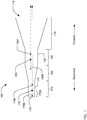
- a dual polarization broadband/multi-band antenna 100 may include a dual band waveguide horn 110, a low band feed section 130, a transition section 150, and a high band feed section 170.
- the dual band waveguide horn 110 may have a forward end with a radiating aperture 112 open to free space.
- the term "forward” will be used in this patent to describe a direction towards the radiating aperture of an antenna, and the terms "back” and “backward” will be used to describe the opposing direction.
- the forward end of an element is in the forward direction and the back end of an element is in the backward direction.
- the dual band waveguide horn 110 may be configured to support the propagation of electromagnetic waves in a low band and a high band.
- band means a range of wavelengths and the terms “low” and “high” are relative.
- the wavelengths contained in the high band are higher than the wavelengths contained in the low band.
- a back end of the dual band waveguide horn 110 may be coupled to a forward end of the low band feed section 130.
- the low band feed section 130 may include a dual band waveguide 132 configured to support the propagation of electromagnetic waves in the low wavelength band and the high wavelength band and at least one low band feed 135 for coupling an electromagnetic waves in the low band into the dual band waveguide 132.
- a back end of the low band feed section 130 may be coupled to a forward end of the transition section 150.
- a back end of the transition section 150 may be coupled to the forward end of the high band feed section 170.
- the high band feed section 170 may include a high band waveguide 172 configured to support the propagation of electromagnetic waves in the high band, but not in the low band, and at least one high band feed 175 for coupling electromagnetic energy in the high band into the high band waveguide 172.
- High band electromagnetic energy coupled into the high band waveguide 172 from the high band feed 175 may propagate as both a forward-propagating high band wave, indicated by the broken line 175F, and a backward-propagating high band wave, indicated by the broken line 175B.
- the back end of the high band waveguide 172 may be closed by a conductive shorting wall 178 configured to inhibit coupling from the high band feed to the backward-propagating high band wave 175B.
- the shorting wall 178 may be disposed, with respect to the high band feed 175, such that the back portion 172B of the high band waveguide appears as a high impedance when viewed from the high band feed 175.
- the back portion 172B of the high band waveguide appears as a high impedance, only a small portion of the high band electromagnetic energy may be coupled from the high band feed 175 into the backward-propagating high band wave 175B.
- the majority of high band electromagnetic energy may be coupled into the forward-propagating high band wave 175F.
- the back portion 172B of the high band waveguide may appear as a high impedance if the shorting wall 178 is positioned about 1 ⁇ 4 of the high band wavelength from the high band feed.
- the forward-propagating high band wave 175F may propagate through the transition section 150 and the dual band waveguide 132 and be radiated into free space via the dual-band waveguide horn 110.
- low band electromagnetic energy coupled into the dual band waveguide 132 from the low band feed 135 may be coupled into both a forward-propagating low band wave, indicated by the broken line 135F, and a backward-propagating low band wave, as indicated by the broken line 135B.
- the transition section 150 may be configured to support through propagation of the high band wave 175F and to inhibit coupling from the low band feed 135 to the backward-propagating low band wave 135B.
- the transition section 150 may appear to the low band feed 135 as a high impedance, such that only a small portion of the low band electromagnetic energy may be coupled from the low band feed 135 into the backward-propagating low band wave 135B.
- the majority of low band electromagnetic energy may be coupled into the forward-propagating low band wave 135F.
- the forward-propagating low band wave 135F may propagate through the dual band waveguide 132 and be radiated into free space via the dual-band waveguide horn 110.
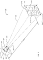
- an exemplary dual polarization broadband/multi-band antenna 200 which may be the antenna 100, may include a waveguide horn 210 which terminates at a forward end in a radiating aperture 212.
- the relative position of various parts of the dual polarization broadband/multi-band antenna 200 will be described using geometrically descriptive terms such as top, bottom, left and right. These terms refer specifically to the orientation as seen in the figures.
- the dual polarization broadband/multi-band antenna 200 may be used in various positions such as upside down.
- geometrically descriptive terms are relative and do not imply any absolute orientation of the dual polarization broadband/multi-band antenna 200.
- the exemplary dual polarization broadband/multi-band antenna 200 of FIG. 2 is configured to operate in a broad low band from 8 GHz to 18 GHz, encompassing the X and Ku bands, and in a high band from 32 GHz to 36 GHz, encompassing a portion of the Ka band.
- the overall length of the dual polarization broadband/multi-band antenna 200 may be about 17 inches, and the radiating aperture 212 may be about 3 inches square.
- Dual polarization broadband/multi-band antennas configured for operation in other bands may have other dimensions.
- the waveguide horn 210 may be a quad ridged waveguide horn.
- the waveguide horn 210 may include four walls 214A, 214B, 214C, 214D which define a waveguide having a generally square cross-section.
- the cross-section of the dual polarization broadband/multi-band antenna 200 may taper in size from the radiating aperture 212 at the forward end to the rearward end proximate to the flange 220.
- Four ridges 216A, 216B, 216C, 216D may extend into the interior of the waveguide horn 210 from the respective walls.
- the back portion of the dual polarization broadband/multi-band antenna 200 may be a feed network, of which only X/Ku band connectors 234, 244 and Ka band connectors 274, 284 are visible in FIG. 2 .
- the two connectors 234, 274 on top of the waveguide horn 210 may be used to couple microwave energy, in their respective bands, having a vertical polarization state.
- the two connectors 244, 284 on the left side of the waveguide horn 210 may be used to couple microwave energy, in their respective bands, having a horizontal polarization state.
- the terms “vertical” and “horizontal” indicate two orthogonal directions for the electric field vector of electromagnetic energy propagating in the waveguide horn 210 and do not imply any absolute orientation of the dual polarization broadband/multi-band antenna 200.
- the dual polarization broadband/multi-band antenna 200 may be mechanically connected to and supported by a flange 220.
- the flange 220 may include mounting holes 222 or other provisions for attaching the dual polarization broadband/multi-band antenna 200 to a supporting structure (not shown).
- Two external ribs 224, 226 may be formed on the right side and bottom of the waveguide horn to couple the weight of the waveguide horn 210 to the flange 220 and to strengthen and stiffen the mechanical structure of the dual polarization broadband/multi-band antenna 200.
- the use of the flange 220 and ribs 224, 226 to mount and support the waveguide horn 210 is exemplary.
- the dual polarization broadband/multi-band antenna 200 may be supported and mounted by some other structure.
- FIG. 3 is a cross-sectional view of the dual polarization broadband/multi-band antenna 200.
- the dual polarization broadband/multi-band antenna 200 may be partitioned into functional components including the waveguide horn 210, and the feed network including a low band feed section 230, a transition section 250, and a high band feed section 270.
- This partition of the components of the dual polarization broadband/multi-band antenna 200 into functional components does not imply that the functional components are physically separable or separately fabricated.
- the interior structure of the waveguide horn 210 including walls 214B, 214C, 214D and corresponding ridges 216B, 216C, 216D, can be seen in FIG. 3 .
- Each of the four ridges has a height h that varies or tapers with position along the length of the waveguide horn 210.
- the flare of the waveguide horn 210 and the taper of the ridges 216B-D may be determined using conventional design techniques given the required bandwidth (including both the low band and the high band) and desired gain for the dual polarization broadband/multi-band antenna 200.
- the dual polarization broadband/multi-band antenna 200 may be designed and simulated using a software tool adapted to solve three-dimensional electromagnetic field problems.
- the software tool may be a commercially available electromagnetic field analysis tool such as CST Microwave StudioTM, Agilent's MomentumTM tool, or Ansoft's HFSSTM tool.
- the electromagnetic field analysis tool may be a proprietary tool using any known mathematical method, such as finite difference time domain analysis, finite element method, boundary element method, method of moments, or other methods for solving electromagnetic field problems.
- the software tool may include a capability to iteratively optimize a design to meet predetermined performance targets.
- FIG. 4 is a perspective cross sectional detail view of the dual polarization broadband/multi-band antenna 200 at a section plane passing through the low band vertical polarization feed connector 234 and the high band vertical polarization feed connector 274.
- the low band feed section 230 may include a dual band waveguide 232 configured to support propagation of both low band and high band electromagnetic waves.
- the dual band waveguide 232 may be, for example, a quad ridged waveguide of essentially the same cross section as the back end of the waveguide horn 210.
- a low band vertical polarization feed may include a probe 238 inserted into the dual band waveguide 232.
- the probe 238 may be coupled to the low band vertical polarization connector 234 through one or more coaxial transformers 236.
- the one or more coaxial transformers may match the impedance of the probe to the impedance of a standard coaxial cable to be connected to the connector 234.
- slots may be cut into two opposing ridges to allow insertion of the probe 238.
- the high band feed section 270 may include a high band waveguide 272 configured to support propagation of high band electromagnetic waves but not support propagation of low band electromagnetic waves.
- the high band waveguide 272 may be, for example, a square waveguide as shown in FIG. 4 .
- a high band vertical polarization feed may include a probe 276 inserted into the high band waveguide 272.
- the high band vertical polarization feed probe 276 may be coupled directly to the high band vertical polarization connector 284.
- the back end of the high band waveguide 272 may be closed by a conductive shorting plate 278.
- the shorting plate 278 may be disposed, with respect to the high band vertical polarization feed probe 276, such that the shorting plate inhibits coupling from the high band vertical polarization feed probe 276 to a backward-propagating high band vertical polarized wave.
- a longitudinal distance between the high band vertical polarization feed probe 276 and the shorting plate 278 may be about 1 ⁇ 4 wavelength for the high band.
- the high band feed section 270 may also include a plurality of horizontal shorting pins 288 positioned forward of the high band vertical polarization feed probe 276.
- the shorting pins 288 may be transparent to forward-propagating vertical polarization waves. As will be described, the shorting pins 288 may be effective to inhibit coupling from a high band horizontal polarization feed probe (not visible in FIG. 4 ) to a backward-propagating high band horizontal polarized wave.
- the forward end of the transition section 250 may have a cross-sectional form essentially the same at that of the dual-band waveguide 232.
- the forward end of the transition section may be a quad ridge waveguide as shown in FIG. 4 .
- the height of the ridges 252 extending from the four walls may taper such that the ridges disappear before the back end of the transition section joins the high band wave guide 272.
- the taper of the ridges 252 in the transition section may be exponential, as shown in FIG. 4 , stepped, linear, or some other taper.
- the taper of the ridges 252 may be configured such that the transition section 250 appears, from the low band feed probe, as a high impedance that inhibits coupling into backward-propagating low band electromagnetic waves.
- FIG. 5 is a perspective cross sectional detail view of the dual polarization broadband/multi-band antenna 200 at a section plane passing through the low band horizontal polarization feed connector 244 and the high band horizontal polarization feed connector 284.
- the low band horizontal polarization feed may include a probe 248 inserted into the dual band waveguide 232.
- the probe 248 may be coupled to the low band horizontal polarization connector 244 through one or more coaxial transformers 246 that match the impedance of the probe to the impedance of a standard coaxial cable to be connected to the connector 244.
- the low band horizontal polarization feed may be essentially the same as the low band vertical polarization feed except for a slight longitudinal offset between the low band horizontal polarization feed probe 248 and the low band vertical polarization feed probe 238.
- the longitudinal offset between the low band horizontal polarization feed probe 248 and the low band vertical polarization feed probe 238 may be small compared to 1 ⁇ 4 wavelength at the low band.
- the high band horizontal polarization feed may include a probe 286 inserted into the high band waveguide 272.
- the probe 286 may be coupled directly to the high band vertical polarization connector 284.
- the high band horizontal polarization feed probe 286 may be disposed, with respect to the shorting pins 288, such that the shorting pins 288 are effective to inhibit coupling from the high band horizontal polarization feed probe 286 to a backward-propagating high band wave.
- a longitudinal distance between the high band horizontal polarization feed probe 286 and the shorting pins 288 may be about 1 ⁇ 4 wavelength at the high band.
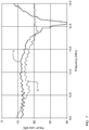
- FIG. 6 and FIG. 7 are graphs of the measured X-band and Ku-band performance of a prototype dual polarization broadband/multi-band antenna similar to the antenna 200 shown in FIG. 2 .
- the gain of the antenna varies from about 15 dB at 8 GHz to about 20 dB at 18 GHz.
- the gain is essentially the same for both vertical and horizontal polarization from 8 GHz to about 17 GHz.
- the return loss is less than -10 dB over nearly the entire 8 GHz - 18 GHz frequency range.
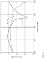
- FIG. 8 and FIG. 9 are graphs of the measured Ka-band performance of the prototype dual polarization broadband/multi-band antenna.
- the gain of the antenna is about 24 dB from 33 GHz to 36 GHz.
- the gain is essentially the same for both vertical and horizontal polarization.
- the return loss is less than -10 dB for both polarization over most of the frequency range from 32 GHz to 36 GHz.
- plural means two or more.
- a “set” of items may include one or more of such items.
- the terms “comprising”, “including”, “carrying”, “having”, “containing”, “involving”, and the like are to be understood to be open-ended, i.e., to mean including but not limited to. Only the transitional phrases “consisting of' and “consisting essentially of', respectively, are closed or semi-closed transitional phrases with respect to claims.
Landscapes
- Waveguide Aerials (AREA)
- Variable-Direction Aerials And Aerial Arrays (AREA)
Claims (12)
- Antenne à bandes multiples à double polarisation (200), comprenant :un guide d'onde comportant une section d'alimentation de bande haute (270), une section de transition (250), une section d'alimentation de bande basse (230) et un cornet guide d'onde à quadruple nervure (210) couplés en série ; dans laquellela section d'alimentation de bande haute est configurée pour permettre la propagation d'ondes électromagnétiques dans une bande haute de longueurs d'ondes et empêcher la propagation d'ondes électromagnétiques dans une bande basse de longueurs d'ondes ;la section de transition est configurée pour coupler des ondes électromagnétiques dans la bande haute provenant de la section d'alimentation de bande haute à la section d'alimentation de bande basse, et empêcher la rétropropagation d'ondes électromagnétiques dans la bande basse ;la section d'alimentation de bande basse est configurée pour permettre la propagation d'ondes électromagnétiques dans la bande basse de longueurs d'ondes et la bande haute de longueurs d'ondes, la section d'alimentation de bande basse comprenant un guide d'onde à quadruple nervure (232), et une alimentation de bande basse horizontale (244/246/248) et une alimentation de bande basse verticale (234/236/238) pour coupler des ondes électromagnétiques de bande base polarisées orthogonalement à propagation directe dans le guide d'onde à quadruple nervure ; et dans laquellele cornet est configuré pour coupler des ondes électromagnétiques dans la bande basse de longueurs d'ondes et la bande haute de longueurs d'ondes provenant de la section d'alimentation de bande basse dans l'espace libre.
- Antenne à bandes multiples à double polarisation (200), selon la revendication 1 dans laquelle la section d'alimentation de bande haute comprend une extrémité avant et une extrémité arrière fermée, la section d'alimentation de bande haute comprenant :un guide d'onde de bande haute (272) configuré pour permettre la propagation d'ondes électromagnétiques dans une bande haute de longueurs d'ondes et empêcher la propagation d'ondes électromagnétiques dans une bande basse de longueurs d'ondes, etune alimentation de bande haute verticale (274/276) et une alimentation de bande haute horizontale (284/286) pour coupler des ondes magnétiques de bande haute polarisées orthogonalement à propagation directe dans le guide d'onde de bande haute ;dans laquelle la section d'alimentation de bande basse (230) comprend une extrémité avant et une extrémité arrière, dans laquelle le guide d'onde à quadruple nervure (232) est configuré pour permettre la propagation d'ondes électromagnétiques dans la bande basse de longueurs d'ondes et la bande haute de longueurs d'ondes ;dans laquelle la section de transition (250) est couplée entre l'extrémité avant de la section d'alimentation de bande haute et l'extrémité arrière de la section d'alimentation de bande basse, la section de transition étant configurée pour coupler des ondes électromagnétiques de bande haute provenant du guide d'onde de bande haute au guide d'onde double bande et inhiber le couplage de l'alimentation de bande basse verticale et l'alimentation de bande basse horizontale dans des ondes électromagnétiques de bande basse à rétropropagation ; etdans laquelle le cornet comprend un cornet guide d'onde double bande (210) s'effilant vers l'extérieur depuis une extrémité arrière couplée à l'extrémité avant de la section d'alimentation de bande basse vers une extrémité avant ouverte à l'espace libre.
- Antenne à bandes multiples à double polarisation selon la revendication 2, dans laquelle le guide d'onde de bande haute comprend un guide d'onde carré (272).
- Antenne à bandes multiples à double polarisation selon la revendication 3, la section d'alimentation de bande basse comprenant en outre :
la sonde de bande basse verticale (238) s'étendant jusque dans le guide d'onde à quadruple nervure, et la sonde de bande basse horizontale (248) s'étendant jusque dans le guide d'onde à quadruple nervure. - Antenne à bandes multiples à double polarisation selon la revendication 4, la section d'alimentation de bande basse comprenant en outre :un connecteur coaxial de bande basse vertical (234) couplé à la sonde de bande basse verticale par le biais d'un ou de plusieurs transformateurs coaxiaux (236) ; etun connecteur coaxial de bande basse horizontal (244) couplé à la sonde de bande basse horizontale par le biais d'un ou de plusieurs transformateurs coaxiaux (246).
- Antenne à bandes multiples à double polarisation selon la revendication 3, la section d'alimentation de bande haute comprenant en outre :un connecteur coaxial de bande haute vertical (274) couplé au guide d'onde carré ; etun connecteur coaxial de bande haute horizontal (284) couplé au guide d'onde carré.
- Antenne à bandes multiples à double polarisation selon la revendication 6, la section d'alimentation de bande haute comprenant en outre :une paroi d'extrémité du guide d'onde carré (278) disposée pour inhiber le couplage depuis l'alimentation de bande haute à polarisation verticale dans une onde électromagnétique de bande haute à rétropropagation polarisée verticalement ; etune pluralité de broches de court-circuit (288) disposée pour inhiber le couplage depuis l'alimentation de bande haute à polarisation horizontale dans des ondes électromagnétiques de bande haute à rétropropagation polarisées horizontalement.
- Antenne à bandes multiples à double polarisation selon la revendication 3, comprenant en outre :une bride de montage (220) proche de l'extrémité arrière de la section d'alimentation de bande haute ; etune ou plusieurs nervures externes (224, 226) s'étendant depuis la bride de montage jusqu'au cornet guide d'onde.
- Antenne à bandes multiples à double polarisation selon la revendication 1, chacune des alimentations de bande basse horizontale et verticale comprenant en outre :une sonde (248, 238) s'étendant jusque dans le guide d'onde à quadruple nervure ;un connecteur (244, 234) ;un ou plusieurs transformateurs coaxiaux (246, 236) pour adapter l'impédance du connecteur à l'impédance de la sonde.
- Antenne à bandes multiples à double polarisation selon la revendication 1, la section d'alimentation de bande haute comprenant en outre :un guide d'onde carré (272) ;une alimentation de bande haute verticale (274/276) pour coupler des ondes électromagnétiques de bande haute polarisées verticalement dans le guide d'onde carré ;une paroi de court-circuit (278) disposée pour inhiber la rétropropagation d'ondes électromagnétiques de bande haute polarisées verticalement ;une alimentation de bande horizontale (284/286) pour coupler des ondes électromagnétiques de bande haute polarisées horizontalement dans le guide d'onde carré ; etune pluralité de broches conductrices (288) disposée pour inhiber la rétropropagation d'ondes électromagnétiques de bande haute polarisées horizontalement.
- Antenne à bandes multiples à double polarisation selon la revendication 10, la section de transition comprenant en outre :un guide d'onde à quadruple nervure (252) dans lequelune hauteur de chaque nervure du guide d'onde à quadruple nervure diminue le long d'une longueur de la section de transition,les nervures ont une hauteur maximale au point de couplage de la section de transition à la section d'alimentation de bande basse, etles nervures disparaissent au point de couplage de la section de transition à la section d'alimentation de bande haute.
- Antenne à bandes multiples à double polarisation selon l'un quelconque des revendications précédentes, dans laquelle la bande basse comporte des fréquences de 8,0 GHz à 18,0 GHz, et la bande haute comporte des fréquences de 32 GHz à 36 GHz.
Applications Claiming Priority (2)
| Application Number | Priority Date | Filing Date | Title |
|---|---|---|---|
| US12/552,231 US8248321B2 (en) | 2009-09-01 | 2009-09-01 | Broadband/multi-band horn antenna with compact integrated feed |
| PCT/US2010/041620 WO2011028323A1 (fr) | 2009-09-01 | 2010-07-09 | Antenne à cornet à large bande/à bandes multiples avec alimentation compacte intégrée |
Publications (3)
| Publication Number | Publication Date |
|---|---|
| EP2474071A1 EP2474071A1 (fr) | 2012-07-11 |
| EP2474071A4 EP2474071A4 (fr) | 2014-04-30 |
| EP2474071B1 true EP2474071B1 (fr) | 2019-03-06 |
Family
ID=43624068
Family Applications (1)
| Application Number | Title | Priority Date | Filing Date |
|---|---|---|---|
| EP10814116.9A Active EP2474071B1 (fr) | 2009-09-01 | 2010-07-09 | Antenne à cornet à large bande/à bandes multiples avec alimentation compacte intégrée |
Country Status (4)
| Country | Link |
|---|---|
| US (1) | US8248321B2 (fr) |
| EP (1) | EP2474071B1 (fr) |
| JP (1) | JP5623530B2 (fr) |
| WO (1) | WO2011028323A1 (fr) |
Families Citing this family (48)
| Publication number | Priority date | Publication date | Assignee | Title |
|---|---|---|---|---|
| US8847838B2 (en) | 2012-01-11 | 2014-09-30 | Rantec Microwave Systems, Inc. | Broadband antenna feed array |
| US9912073B2 (en) | 2012-03-16 | 2018-03-06 | Raytheon Company | Ridged waveguide flared radiator antenna |
| US9310481B2 (en) * | 2012-05-31 | 2016-04-12 | LogLinear Group, LLC | Wide band clear air scatter doppler radar |
| US9851470B2 (en) | 2013-03-12 | 2017-12-26 | LogLinear Group, LLC | Single beam FMCW radar wind speed and direction determination |
| KR101427148B1 (ko) * | 2013-03-21 | 2014-08-07 | 국방과학연구소 | 방위각 방향 빔폭을 향상시키는 리지드 혼안테나 |
| US9391692B2 (en) * | 2013-07-05 | 2016-07-12 | Gilat Satellite Networks Ltd. | System for dual frequency range mobile two-way satellite communications |
| WO2015035463A1 (fr) * | 2013-09-13 | 2015-03-19 | Commonwealth Scientific And Industrial Research Organisation | Cornet d'alimentation avec quatre arêtes comportant un pointeau diélectrique |
| US9323877B2 (en) | 2013-11-12 | 2016-04-26 | Raytheon Company | Beam-steered wide bandwidth electromagnetic band gap antenna |
| KR101532322B1 (ko) * | 2014-01-14 | 2015-07-09 | 국방과학연구소 | 혼안테나 |
| US9300042B2 (en) | 2014-01-24 | 2016-03-29 | Honeywell International Inc. | Matching and pattern control for dual band concentric antenna feed |
| JP6257401B2 (ja) * | 2014-03-20 | 2018-01-10 | 三菱電機株式会社 | アンテナ装置 |
| DE102015102002A1 (de) | 2015-02-12 | 2016-08-18 | Endress + Hauser Gmbh + Co. Kg | Vorrichtung zur Ermittlung und Überwachung eines Füllstands |
| US9425511B1 (en) | 2015-03-17 | 2016-08-23 | Northrop Grumman Systems Corporation | Excitation method of coaxial horn for wide bandwidth and circular polarization |
| US20170040709A1 (en) * | 2015-08-04 | 2017-02-09 | Nidec Elesys Corporation | Radar apparatus |
| US9431715B1 (en) | 2015-08-04 | 2016-08-30 | Northrop Grumman Systems Corporation | Compact wide band, flared horn antenna with launchers for generating circular polarized sum and difference patterns |
| US10249953B2 (en) | 2015-11-10 | 2019-04-02 | Raytheon Company | Directive fixed beam ramp EBG antenna |
| CN105470650B (zh) * | 2015-12-02 | 2018-06-26 | 成都润博科技有限公司 | 一种高灵敏性智能后馈式双脊天线 |
| US10326213B2 (en) | 2015-12-17 | 2019-06-18 | Viasat, Inc. | Multi-band antenna for communication with multiple co-located satellites |
| CN107069189B (zh) * | 2017-01-20 | 2019-10-29 | 中国人民解放军63921部队 | 一种多频段宽带双极化加脊喇叭天线 |
| CN108987925B (zh) * | 2018-07-17 | 2019-07-09 | 江苏肯立科技股份有限公司 | 双频圆波导四脊喇叭天线 |
| CN109755750B (zh) * | 2019-03-08 | 2020-10-20 | 北京航空航天大学 | 一种宽带加脊正交模式变换器馈电的双极化馈源 |
| CN109786929B (zh) * | 2019-03-08 | 2020-10-16 | 北京航空航天大学 | 一种波纹槽四脊喇叭馈源 |
| KR102087808B1 (ko) * | 2019-03-29 | 2020-03-11 | 이홍재 | 듀얼폴 혼 안테나 및 그 제조방법 |
| CN110416725A (zh) * | 2019-08-21 | 2019-11-05 | 中国安全生产科学研究院 | 一种高增益介质喇叭天线 |
| US11075461B2 (en) | 2019-12-16 | 2021-07-27 | City University Of Hong Kong | Horn antenna |
| FR3105884B1 (fr) * | 2019-12-26 | 2021-12-03 | Thales Sa | Cornet pour antenne satellite bi-bande Ka à polarisation circulaire |
| CN113126173B (zh) * | 2019-12-30 | 2022-06-03 | 清华大学 | 被动式安检设备及其接收天线单元 |
| CN111463577B (zh) * | 2020-03-05 | 2022-11-01 | 中国电子科技集团公司第二十九研究所 | 一种螺纹连接的双脊喇叭天线馈电结构 |
| USD978843S1 (en) * | 2020-12-18 | 2023-02-21 | Nan Hu | Broadband horn antenna |
| USD977464S1 (en) * | 2020-12-21 | 2023-02-07 | Nan Hu | Ultra-wideband horn antenna |
| USD983773S1 (en) * | 2021-01-07 | 2023-04-18 | Nan Hu | Ultra-wideband dual polarization horn antenna |
| USD972538S1 (en) * | 2021-01-21 | 2022-12-13 | Nan Hu | Ultra-wideband horn antenna |
| USD977465S1 (en) * | 2021-01-21 | 2023-02-07 | Nan Hu | Ultra-wideband horn antenna |
| USD976881S1 (en) * | 2021-02-05 | 2023-01-31 | Nan Hu | Broadband dual-polarization horn antenna |
| USD975690S1 (en) * | 2021-02-16 | 2023-01-17 | Nan Hu | Ultra-wideband dual polarization horn antenna |
| USD1003875S1 (en) * | 2021-04-15 | 2023-11-07 | Nan Hu | Corrugated feed horn antenna |
| USD1008234S1 (en) * | 2021-04-21 | 2023-12-19 | Nan Hu | Corrugated feed horn antenna |
| USD1006800S1 (en) * | 2021-04-29 | 2023-12-05 | Nan Hu | Dual linear polarization conical horn antenna |
| US12355158B1 (en) * | 2021-07-08 | 2025-07-08 | Lockheed Martin Corporation | Vivaldi antenna structures with concurrent transmit and receive |
| US12512596B1 (en) * | 2021-11-04 | 2025-12-30 | Lockheed Martin Corporation | Longitudinally ridged quad polarizer feed |
| CN114597636B (zh) * | 2021-12-23 | 2024-08-09 | 南京软赫电子科技有限公司 | 一种宽频超低轮廓双极化天线 |
| CN114361801B (zh) * | 2021-12-28 | 2023-10-13 | 昆山荷兹天线微波技术有限公司 | 一种双极化高隔离度l波段小型化喇叭天线 |
| US11936112B1 (en) | 2022-05-05 | 2024-03-19 | Lockheed Martin Corporation | Aperture antenna structures with concurrent transmit and receive |
| CN115693159B (zh) * | 2022-10-25 | 2025-11-25 | 北京航空航天大学 | 一种宽带双极化四脊馈电圆波导喇叭馈源 |
| CN116404383A (zh) * | 2023-03-31 | 2023-07-07 | 中国电子科技集团公司第五十四研究所 | 一种方波导过渡器 |
| CN116632544A (zh) * | 2023-06-06 | 2023-08-22 | 中国科学院国家天文台 | 一种低频超宽带四脊喇叭馈源 |
| CN116581550B (zh) * | 2023-07-11 | 2023-11-24 | 银河航天(西安)科技有限公司 | 一种馈源组件及馈源系统 |
| CN119231182B (zh) * | 2024-10-12 | 2025-09-05 | 西安伊鼎智能科技有限公司 | 一种小频比宽带双频双圆极化同轴共口径喇叭天线单元 |
Family Cites Families (18)
| Publication number | Priority date | Publication date | Assignee | Title |
|---|---|---|---|---|
| US3325817A (en) | 1964-06-01 | 1967-06-13 | Hughes Aircraft Co | Dual frequency horn antenna |
| US3380057A (en) | 1965-07-20 | 1968-04-23 | Motorola Inc | Dual band ridged feed horn |
| US3389394A (en) | 1965-11-26 | 1968-06-18 | Radiation Inc | Multiple frequency antenna |
| US3566309A (en) | 1969-02-24 | 1971-02-23 | Hughes Aircraft Co | Dual frequency band,polarization diverse tracking feed system for a horn antenna |
| US3742506A (en) | 1971-03-01 | 1973-06-26 | Communications Satellite Corp | Dual frequency dual polarized antenna feed with arbitrary alignment of transmit and receive polarization |
| DE2443166C3 (de) | 1974-09-10 | 1985-05-30 | ANT Nachrichtentechnik GmbH, 7150 Backnang | Systemweiche zur Trennung zweier Signale, die aus je zwei doppelt polarisierten Frequenzbändern bestehen |
| US5406298A (en) | 1985-04-01 | 1995-04-11 | The United States Of America As Represented By The Secretary Of The Navy | Small wideband passive/active antenna |
| US4821046A (en) * | 1986-08-21 | 1989-04-11 | Wilkes Brian J | Dual band feed system |
| US4737741A (en) * | 1986-10-20 | 1988-04-12 | Hughes Aircraft Company | Orthogonal mode electromagnetic wave launcher |
| US4792814A (en) | 1986-10-23 | 1988-12-20 | Mitsubishi Denki Kabushiki Kaisha | Conical horn antenna applicable to plural modes of electromagnetic waves |
| US4876061A (en) | 1986-11-03 | 1989-10-24 | Westinghouse Electric Corp. | Resiliently loaded lateral supports for cantilever-mounted rod guides of a pressurized water reactor |
| US4878061A (en) * | 1988-11-25 | 1989-10-31 | Valentine Research, Inc. | Broadband wide flare ridged microwave horn antenna |
| JPH09307305A (ja) * | 1996-05-20 | 1997-11-28 | Fujitsu General Ltd | 直線偏波用フィードホーン |
| US6603438B2 (en) | 2001-02-22 | 2003-08-05 | Ems Technologies Canada Ltd. | High power broadband feed |
| US6624792B1 (en) | 2002-05-16 | 2003-09-23 | Titan Systems, Corporation | Quad-ridged feed horn with two coplanar probes |
| US6906676B2 (en) | 2003-11-12 | 2005-06-14 | Harris Corporation | FSS feeding network for a multi-band compact horn |
| US6937203B2 (en) | 2003-11-14 | 2005-08-30 | The Boeing Company | Multi-band antenna system supporting multiple communication services |
| US7161550B2 (en) * | 2004-04-20 | 2007-01-09 | Tdk Corporation | Dual- and quad-ridged horn antenna with improved antenna pattern characteristics |
-
2009
- 2009-09-01 US US12/552,231 patent/US8248321B2/en active Active
-
2010
- 2010-07-09 EP EP10814116.9A patent/EP2474071B1/fr active Active
- 2010-07-09 JP JP2012526757A patent/JP5623530B2/ja active Active
- 2010-07-09 WO PCT/US2010/041620 patent/WO2011028323A1/fr not_active Ceased
Non-Patent Citations (1)
| Title |
|---|
| None * |
Also Published As
| Publication number | Publication date |
|---|---|
| JP2013504222A (ja) | 2013-02-04 |
| WO2011028323A1 (fr) | 2011-03-10 |
| US20110050527A1 (en) | 2011-03-03 |
| EP2474071A4 (fr) | 2014-04-30 |
| JP5623530B2 (ja) | 2014-11-12 |
| US8248321B2 (en) | 2012-08-21 |
| EP2474071A1 (fr) | 2012-07-11 |
Similar Documents
| Publication | Publication Date | Title |
|---|---|---|
| EP2474071B1 (fr) | Antenne à cornet à large bande/à bandes multiples avec alimentation compacte intégrée | |
| CN102136634B (zh) | 一种Ku/Ka频段线圆极化一体化收发馈源天线 | |
| US9520637B2 (en) | Agile diverse polarization multi-frequency band antenna feed with rotatable integrated distributed transceivers | |
| CN108432049B (zh) | 有效平面相控阵列天线组件 | |
| US8013687B2 (en) | Ortho-mode transducer with TEM probe for coaxial waveguide | |
| US7944324B2 (en) | Compact orthomode transduction device optimized in the mesh plane, for an antenna | |
| Piltyay | Enhanced C-band coaxial orthomode transducer | |
| WO2011094121A1 (fr) | Procédé et appareil d'alimentation trois bandes avec poursuite par pseudo monoimpulsion | |
| CN104428948A (zh) | 包括具有几何收缩的喇叭天线的、用于GHz频率范围的宽带卫星通信的天线系统 | |
| US8089415B1 (en) | Multiband radar feed system and method | |
| CA1208719A (fr) | Adaptateur de ligne coaxiale a un guide d'ondes | |
| KR100815154B1 (ko) | 도파관 구조를 가지는 위성통신 다중대역 안테나의 급전장치 | |
| US8305157B2 (en) | Waveguide adapter for converting linearly polarized waves into a circularly polarized wave including an impedance matching metal grate member | |
| US6452561B1 (en) | High-isolation broadband polarization diverse circular waveguide feed | |
| CN206850013U (zh) | 一种透镜加载圆极化喇叭天线 | |
| Zhang et al. | Efficient design of axially corrugated coaxial-type multi-band horns for reflector antennas | |
| US7852277B2 (en) | Circularly polarized horn antenna | |
| US4558290A (en) | Compact broadband rectangular to coaxial waveguide junction | |
| Holzman | A wide band TEM horn array radiator with a novel microstrip feed | |
| GB2479151A (en) | A hollow ridge dual channel waveguide that is operable using at least two bands comprising at least a first waveguide and a second waveguide. | |
| CN115441167A (zh) | 集成有双工器的紧凑型低剖面开孔天线 | |
| KR20220067491A (ko) | 전방향성 밀리미터파 안테나 | |
| Amjadi et al. | A compact, broadband, two-port slot antenna system for full-duplex applications | |
| KR102112202B1 (ko) | 편파 변환 일체형 혼 안테나 및 그 제조 방법 | |
| Chung | Design of a Dual-band Feed System for S/X-band VLBI Observations |
Legal Events
| Date | Code | Title | Description |
|---|---|---|---|
| PUAI | Public reference made under article 153(3) epc to a published international application that has entered the european phase |
Free format text: ORIGINAL CODE: 0009012 |
|
| 17P | Request for examination filed |
Effective date: 20120315 |
|
| AK | Designated contracting states |
Kind code of ref document: A1 Designated state(s): AL AT BE BG CH CY CZ DE DK EE ES FI FR GB GR HR HU IE IS IT LI LT LU LV MC MK MT NL NO PL PT RO SE SI SK SM TR |
|
| DAX | Request for extension of the european patent (deleted) | ||
| A4 | Supplementary search report drawn up and despatched |
Effective date: 20140327 |
|
| RIC1 | Information provided on ipc code assigned before grant |
Ipc: H01Q 13/02 20060101AFI20140321BHEP Ipc: H01Q 21/24 20060101ALI20140321BHEP Ipc: H01Q 5/00 20060101ALI20140321BHEP |
|
| STAA | Information on the status of an ep patent application or granted ep patent |
Free format text: STATUS: EXAMINATION IS IN PROGRESS |
|
| 17Q | First examination report despatched |
Effective date: 20170130 |
|
| GRAP | Despatch of communication of intention to grant a patent |
Free format text: ORIGINAL CODE: EPIDOSNIGR1 |
|
| STAA | Information on the status of an ep patent application or granted ep patent |
Free format text: STATUS: GRANT OF PATENT IS INTENDED |
|
| INTG | Intention to grant announced |
Effective date: 20180809 |
|
| GRAJ | Information related to disapproval of communication of intention to grant by the applicant or resumption of examination proceedings by the epo deleted |
Free format text: ORIGINAL CODE: EPIDOSDIGR1 |
|
| STAA | Information on the status of an ep patent application or granted ep patent |
Free format text: STATUS: EXAMINATION IS IN PROGRESS |
|
| INTC | Intention to grant announced (deleted) | ||
| GRAR | Information related to intention to grant a patent recorded |
Free format text: ORIGINAL CODE: EPIDOSNIGR71 |
|
| GRAS | Grant fee paid |
Free format text: ORIGINAL CODE: EPIDOSNIGR3 |
|
| STAA | Information on the status of an ep patent application or granted ep patent |
Free format text: STATUS: GRANT OF PATENT IS INTENDED |
|
| GRAA | (expected) grant |
Free format text: ORIGINAL CODE: 0009210 |
|
| STAA | Information on the status of an ep patent application or granted ep patent |
Free format text: STATUS: THE PATENT HAS BEEN GRANTED |
|
| INTG | Intention to grant announced |
Effective date: 20190123 |
|
| AK | Designated contracting states |
Kind code of ref document: B1 Designated state(s): AL AT BE BG CH CY CZ DE DK EE ES FI FR GB GR HR HU IE IS IT LI LT LU LV MC MK MT NL NO PL PT RO SE SI SK SM TR |
|
| REG | Reference to a national code |
Ref country code: GB Ref legal event code: FG4D |
|
| REG | Reference to a national code |
Ref country code: CH Ref legal event code: EP Ref country code: AT Ref legal event code: REF Ref document number: 1105798 Country of ref document: AT Kind code of ref document: T Effective date: 20190315 |
|
| REG | Reference to a national code |
Ref country code: DE Ref legal event code: R096 Ref document number: 602010057440 Country of ref document: DE |
|
| REG | Reference to a national code |
Ref country code: IE Ref legal event code: FG4D |
|
| REG | Reference to a national code |
Ref country code: NL Ref legal event code: MP Effective date: 20190306 |
|
| REG | Reference to a national code |
Ref country code: LT Ref legal event code: MG4D |
|
| PG25 | Lapsed in a contracting state [announced via postgrant information from national office to epo] |
Ref country code: NO Free format text: LAPSE BECAUSE OF FAILURE TO SUBMIT A TRANSLATION OF THE DESCRIPTION OR TO PAY THE FEE WITHIN THE PRESCRIBED TIME-LIMIT Effective date: 20190606 Ref country code: FI Free format text: LAPSE BECAUSE OF FAILURE TO SUBMIT A TRANSLATION OF THE DESCRIPTION OR TO PAY THE FEE WITHIN THE PRESCRIBED TIME-LIMIT Effective date: 20190306 Ref country code: SE Free format text: LAPSE BECAUSE OF FAILURE TO SUBMIT A TRANSLATION OF THE DESCRIPTION OR TO PAY THE FEE WITHIN THE PRESCRIBED TIME-LIMIT Effective date: 20190306 Ref country code: LT Free format text: LAPSE BECAUSE OF FAILURE TO SUBMIT A TRANSLATION OF THE DESCRIPTION OR TO PAY THE FEE WITHIN THE PRESCRIBED TIME-LIMIT Effective date: 20190306 |
|
| PG25 | Lapsed in a contracting state [announced via postgrant information from national office to epo] |
Ref country code: HR Free format text: LAPSE BECAUSE OF FAILURE TO SUBMIT A TRANSLATION OF THE DESCRIPTION OR TO PAY THE FEE WITHIN THE PRESCRIBED TIME-LIMIT Effective date: 20190306 Ref country code: NL Free format text: LAPSE BECAUSE OF FAILURE TO SUBMIT A TRANSLATION OF THE DESCRIPTION OR TO PAY THE FEE WITHIN THE PRESCRIBED TIME-LIMIT Effective date: 20190306 Ref country code: LV Free format text: LAPSE BECAUSE OF FAILURE TO SUBMIT A TRANSLATION OF THE DESCRIPTION OR TO PAY THE FEE WITHIN THE PRESCRIBED TIME-LIMIT Effective date: 20190306 Ref country code: GR Free format text: LAPSE BECAUSE OF FAILURE TO SUBMIT A TRANSLATION OF THE DESCRIPTION OR TO PAY THE FEE WITHIN THE PRESCRIBED TIME-LIMIT Effective date: 20190607 Ref country code: BG Free format text: LAPSE BECAUSE OF FAILURE TO SUBMIT A TRANSLATION OF THE DESCRIPTION OR TO PAY THE FEE WITHIN THE PRESCRIBED TIME-LIMIT Effective date: 20190606 |
|
| REG | Reference to a national code |
Ref country code: AT Ref legal event code: MK05 Ref document number: 1105798 Country of ref document: AT Kind code of ref document: T Effective date: 20190306 |
|
| PG25 | Lapsed in a contracting state [announced via postgrant information from national office to epo] |
Ref country code: IT Free format text: LAPSE BECAUSE OF FAILURE TO SUBMIT A TRANSLATION OF THE DESCRIPTION OR TO PAY THE FEE WITHIN THE PRESCRIBED TIME-LIMIT Effective date: 20190306 Ref country code: RO Free format text: LAPSE BECAUSE OF FAILURE TO SUBMIT A TRANSLATION OF THE DESCRIPTION OR TO PAY THE FEE WITHIN THE PRESCRIBED TIME-LIMIT Effective date: 20190306 Ref country code: EE Free format text: LAPSE BECAUSE OF FAILURE TO SUBMIT A TRANSLATION OF THE DESCRIPTION OR TO PAY THE FEE WITHIN THE PRESCRIBED TIME-LIMIT Effective date: 20190306 Ref country code: AL Free format text: LAPSE BECAUSE OF FAILURE TO SUBMIT A TRANSLATION OF THE DESCRIPTION OR TO PAY THE FEE WITHIN THE PRESCRIBED TIME-LIMIT Effective date: 20190306 Ref country code: ES Free format text: LAPSE BECAUSE OF FAILURE TO SUBMIT A TRANSLATION OF THE DESCRIPTION OR TO PAY THE FEE WITHIN THE PRESCRIBED TIME-LIMIT Effective date: 20190306 Ref country code: CZ Free format text: LAPSE BECAUSE OF FAILURE TO SUBMIT A TRANSLATION OF THE DESCRIPTION OR TO PAY THE FEE WITHIN THE PRESCRIBED TIME-LIMIT Effective date: 20190306 Ref country code: SK Free format text: LAPSE BECAUSE OF FAILURE TO SUBMIT A TRANSLATION OF THE DESCRIPTION OR TO PAY THE FEE WITHIN THE PRESCRIBED TIME-LIMIT Effective date: 20190306 Ref country code: PT Free format text: LAPSE BECAUSE OF FAILURE TO SUBMIT A TRANSLATION OF THE DESCRIPTION OR TO PAY THE FEE WITHIN THE PRESCRIBED TIME-LIMIT Effective date: 20190706 |
|
| PG25 | Lapsed in a contracting state [announced via postgrant information from national office to epo] |
Ref country code: PL Free format text: LAPSE BECAUSE OF FAILURE TO SUBMIT A TRANSLATION OF THE DESCRIPTION OR TO PAY THE FEE WITHIN THE PRESCRIBED TIME-LIMIT Effective date: 20190306 Ref country code: SM Free format text: LAPSE BECAUSE OF FAILURE TO SUBMIT A TRANSLATION OF THE DESCRIPTION OR TO PAY THE FEE WITHIN THE PRESCRIBED TIME-LIMIT Effective date: 20190306 |
|
| REG | Reference to a national code |
Ref country code: DE Ref legal event code: R097 Ref document number: 602010057440 Country of ref document: DE |
|
| PG25 | Lapsed in a contracting state [announced via postgrant information from national office to epo] |
Ref country code: AT Free format text: LAPSE BECAUSE OF FAILURE TO SUBMIT A TRANSLATION OF THE DESCRIPTION OR TO PAY THE FEE WITHIN THE PRESCRIBED TIME-LIMIT Effective date: 20190306 Ref country code: IS Free format text: LAPSE BECAUSE OF FAILURE TO SUBMIT A TRANSLATION OF THE DESCRIPTION OR TO PAY THE FEE WITHIN THE PRESCRIBED TIME-LIMIT Effective date: 20190706 |
|
| PLBE | No opposition filed within time limit |
Free format text: ORIGINAL CODE: 0009261 |
|
| STAA | Information on the status of an ep patent application or granted ep patent |
Free format text: STATUS: NO OPPOSITION FILED WITHIN TIME LIMIT |
|
| PG25 | Lapsed in a contracting state [announced via postgrant information from national office to epo] |
Ref country code: DK Free format text: LAPSE BECAUSE OF FAILURE TO SUBMIT A TRANSLATION OF THE DESCRIPTION OR TO PAY THE FEE WITHIN THE PRESCRIBED TIME-LIMIT Effective date: 20190306 |
|
| 26N | No opposition filed |
Effective date: 20191209 |
|
| PG25 | Lapsed in a contracting state [announced via postgrant information from national office to epo] |
Ref country code: SI Free format text: LAPSE BECAUSE OF FAILURE TO SUBMIT A TRANSLATION OF THE DESCRIPTION OR TO PAY THE FEE WITHIN THE PRESCRIBED TIME-LIMIT Effective date: 20190306 Ref country code: MC Free format text: LAPSE BECAUSE OF FAILURE TO SUBMIT A TRANSLATION OF THE DESCRIPTION OR TO PAY THE FEE WITHIN THE PRESCRIBED TIME-LIMIT Effective date: 20190306 |
|
| REG | Reference to a national code |
Ref country code: CH Ref legal event code: PL |
|
| PG25 | Lapsed in a contracting state [announced via postgrant information from national office to epo] |
Ref country code: TR Free format text: LAPSE BECAUSE OF FAILURE TO SUBMIT A TRANSLATION OF THE DESCRIPTION OR TO PAY THE FEE WITHIN THE PRESCRIBED TIME-LIMIT Effective date: 20190306 |
|
| REG | Reference to a national code |
Ref country code: BE Ref legal event code: MM Effective date: 20190731 |
|
| PG25 | Lapsed in a contracting state [announced via postgrant information from national office to epo] |
Ref country code: LU Free format text: LAPSE BECAUSE OF NON-PAYMENT OF DUE FEES Effective date: 20190709 Ref country code: BE Free format text: LAPSE BECAUSE OF NON-PAYMENT OF DUE FEES Effective date: 20190731 Ref country code: CH Free format text: LAPSE BECAUSE OF NON-PAYMENT OF DUE FEES Effective date: 20190731 Ref country code: LI Free format text: LAPSE BECAUSE OF NON-PAYMENT OF DUE FEES Effective date: 20190731 |
|
| PG25 | Lapsed in a contracting state [announced via postgrant information from national office to epo] |
Ref country code: IE Free format text: LAPSE BECAUSE OF NON-PAYMENT OF DUE FEES Effective date: 20190709 |
|
| PG25 | Lapsed in a contracting state [announced via postgrant information from national office to epo] |
Ref country code: CY Free format text: LAPSE BECAUSE OF FAILURE TO SUBMIT A TRANSLATION OF THE DESCRIPTION OR TO PAY THE FEE WITHIN THE PRESCRIBED TIME-LIMIT Effective date: 20190306 |
|
| PG25 | Lapsed in a contracting state [announced via postgrant information from national office to epo] |
Ref country code: MT Free format text: LAPSE BECAUSE OF FAILURE TO SUBMIT A TRANSLATION OF THE DESCRIPTION OR TO PAY THE FEE WITHIN THE PRESCRIBED TIME-LIMIT Effective date: 20190306 Ref country code: HU Free format text: LAPSE BECAUSE OF FAILURE TO SUBMIT A TRANSLATION OF THE DESCRIPTION OR TO PAY THE FEE WITHIN THE PRESCRIBED TIME-LIMIT; INVALID AB INITIO Effective date: 20100709 |
|
| PG25 | Lapsed in a contracting state [announced via postgrant information from national office to epo] |
Ref country code: MK Free format text: LAPSE BECAUSE OF FAILURE TO SUBMIT A TRANSLATION OF THE DESCRIPTION OR TO PAY THE FEE WITHIN THE PRESCRIBED TIME-LIMIT Effective date: 20190306 |
|
| P01 | Opt-out of the competence of the unified patent court (upc) registered |
Effective date: 20230530 |
|
| PGFP | Annual fee paid to national office [announced via postgrant information from national office to epo] |
Ref country code: GB Payment date: 20250619 Year of fee payment: 16 |
|
| PGFP | Annual fee paid to national office [announced via postgrant information from national office to epo] |
Ref country code: FR Payment date: 20250620 Year of fee payment: 16 |
|
| PGFP | Annual fee paid to national office [announced via postgrant information from national office to epo] |
Ref country code: DE Payment date: 20250620 Year of fee payment: 16 |