EP2474087B1 - Procédé et appareil destinés à calculer des indices d'insertion pour un convertisseur modulaire à niveaux multiples - Google Patents
Procédé et appareil destinés à calculer des indices d'insertion pour un convertisseur modulaire à niveaux multiples Download PDFInfo
- Publication number
- EP2474087B1 EP2474087B1 EP20100768192 EP10768192A EP2474087B1 EP 2474087 B1 EP2474087 B1 EP 2474087B1 EP 20100768192 EP20100768192 EP 20100768192 EP 10768192 A EP10768192 A EP 10768192A EP 2474087 B1 EP2474087 B1 EP 2474087B1
- Authority
- EP
- European Patent Office
- Prior art keywords
- arm
- voltage
- diff
- calculating
- phase leg
- Prior art date
- Legal status (The legal status is an assumption and is not a legal conclusion. Google has not performed a legal analysis and makes no representation as to the accuracy of the status listed.)
- Active
Links
Images


Classifications
-
- H—ELECTRICITY
- H02—GENERATION; CONVERSION OR DISTRIBUTION OF ELECTRIC POWER
- H02M—APPARATUS FOR CONVERSION BETWEEN AC AND AC, BETWEEN AC AND DC, OR BETWEEN DC AND DC, AND FOR USE WITH MAINS OR SIMILAR POWER SUPPLY SYSTEMS; CONVERSION OF DC OR AC INPUT POWER INTO SURGE OUTPUT POWER; CONTROL OR REGULATION THEREOF
- H02M7/00—Conversion of AC power input into DC power output; Conversion of DC power input into AC power output
- H02M7/42—Conversion of DC power input into AC power output without possibility of reversal
- H02M7/44—Conversion of DC power input into AC power output without possibility of reversal by static converters
- H02M7/48—Conversion of DC power input into AC power output without possibility of reversal by static converters using discharge tubes with control electrode or semiconductor devices with control electrode
- H02M7/483—Converters with outputs that each can have more than two voltages levels
- H02M7/4835—Converters with outputs that each can have more than two voltages levels comprising two or more cells, each including a switchable capacitor, the capacitors having a nominal charge voltage which corresponds to a given fraction of the input voltage, and the capacitors being selectively connected in series to determine the instantaneous output voltage
-
- H—ELECTRICITY
- H02—GENERATION; CONVERSION OR DISTRIBUTION OF ELECTRIC POWER
- H02M—APPARATUS FOR CONVERSION BETWEEN AC AND AC, BETWEEN AC AND DC, OR BETWEEN DC AND DC, AND FOR USE WITH MAINS OR SIMILAR POWER SUPPLY SYSTEMS; CONVERSION OF DC OR AC INPUT POWER INTO SURGE OUTPUT POWER; CONTROL OR REGULATION THEREOF
- H02M7/00—Conversion of AC power input into DC power output; Conversion of DC power input into AC power output
- H02M7/42—Conversion of DC power input into AC power output without possibility of reversal
- H02M7/44—Conversion of DC power input into AC power output without possibility of reversal by static converters
- H02M7/48—Conversion of DC power input into AC power output without possibility of reversal by static converters using discharge tubes with control electrode or semiconductor devices with control electrode
- H02M7/483—Converters with outputs that each can have more than two voltages levels
- H02M7/49—Combination of the output voltage waveforms of a plurality of converters
Definitions
- the invention relates to the calculation of insertion indices comprising data representing the portion of available submodules of a modular multilevel converter that should be in voltage insert mode.
- Modular Multilevel Converter denotes a class of Voltage Source Converter (VSC). It has one or several phase legs connected in parallel between two DC bars, a positive DC+ and a negative DC-. Each phase leg consists of two series-connected converter arms. The connection point between the converter arms constitutes an AC terminal for the leg.
- Each arm consists of a number (N) of submodules.
- Each submodule has two terminals. Using these terminals the submodules in each arm are series-connected so that they form a string. The end terminals of the string constitute the connection terminals of the arm.
- Such a converter is known from DE10103031 .
- a modulator determines when the number of inserted submodules shall change.
- the principle for equalizing is that, at each instant when a change of the number of inserted submodules is commanded, a selection mechanism chooses the submodule to be inserted or bypassed depending on the actual current direction in the arm (charging or discharging) and the corresponding available submodules in the arm (bypassed highest voltage/bypassed lowest voltage/inserted highest voltage/inserted lowest voltage).
- Such a selection mechanism aims to achieve that the DC voltage across the DC capacitors in the submodules are equal, u C,SM (t).
- a problem with the prior art is the presence of a circulation current going through the legs between the DC terminals.
- M2C modular multilevel converter
- An object of the invention is to reduce circulation currents going through the legs between the DC terminals.
- a first aspect is a method for calculating insertion indices for a phase leg of a DC to AC modular multilevel converter, the converter comprising one phase leg between upper and lower DC source common bars for each phase, each phase leg comprising two serially connected arms, wherein an AC output for each phase leg is connected between its two serially connected arms.
- Each arm comprises a number of submodules, wherein each submodule can be in a bypass state or a voltage insert mode, the insertion index comprising data representing the portion of available submodules that should be in the voltage insert mode for a particular arm.
- the method comprises the steps of: calculating a desired arm voltage for an upper arm connected to the upper DC source common bar and a lower arm connected to the lower DC source common bar, obtaining values representing actual total arm voltages in the upper arm and lower arm, respectively, and calculating insertion indices for the upper and lower arm, respectively, using the respective desired arm voltage and the respective value representing the total actual arm voltage.
- the step of obtaining values representing actual arm voltages may comprise: calculating u CU ⁇ t , actual voltage for the upper arm, using C arm , capacitance for the arm, î diff0 , DC current passing through the two serially connected arms of the phase leg, W CU ⁇ t , desired average energy in the upper arm, ê v , amplitude of reference for the inner AC output voltage, î v , amplitude of AC output current, ⁇ , a phase difference between i v (t) and e v (t), DC current circulating through the two series-connected arms, and calculating u CL ⁇ t , actual voltage for the lower arm, using C arm , capacitance for the arm,l ⁇ diff0 , DC current passing through the two serially connected arms of the phase leg, W CL ⁇ t , desired average energy in the lower arm, ê v , amplitude of reference for inner AC output voltage,l ⁇ v , amplitude of AC output current ⁇ , a phase difference between
- the step of obtaining a value representing actual arm voltage may comprise measuring voltages of the submodules of the arm and summing these measured voltages.
- the insertion index may comprise data representing a direction of the inserted voltage.
- a second aspect is an apparatus for calculating insertion indices for a phase leg of a DC to AC modular multilevel converter, the converter comprising one phase leg between upper and lower DC source common bars for each phase, each phase leg comprising two serially connected arms, wherein an AC output for each phase leg is connected between its two serially connected arms, wherein each arm comprises a number of submodules.
- Each submodule can be in a bypass state or a voltage insert mode, the insertion index comprising data representing the portion of available submodules that should be in the voltage insert mode for a particular arm.
- the apparatus comprises a controller arranged to calculate a desired arm voltage for an upper arm connected to the upper DC source common bar and a lower arm connected to the lower DC source common bar, to obtain values representing actual total arm voltages in the upper arm and lower arm, respectively, and to calculate modulation indices for the upper and lower arm, respectively, using the respective desired arm voltage and the respective value representing the total actual arm voltage.
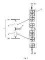
- Fig 1 shows an M2C (Modular Multilevel Converter) having a phase leg 7 that comprising an upper arm 5 and a lower arm 6.
- Each arm 5, 6 comprising a number of serially connected submodules 9.
- Each submodule 9 comprises a switchable capacitor.
- An AC output 8 is connected between the upper and lower arms 5, 6.
- the M2C comprises one phase leg 7 for each phase, i.e. three phase legs 7 for a three phase system, where each phase leg 7 comprises upper and lower arms 5, 6 comprising submodules 9.
- An upper DC source common bar (in this case DC+) and a lower DC source common bar (in this case DC-) for each phase is provided. It is to be noted that the upper and lower DC source common bars can switch polarity.
- the capacitors keep a constant DC voltage and the AC terminal voltage is controlled by varying the number of inserted modules in the upper and lower arms. If the voltage between the DC bars is constant this obviously requires that, in average, the total number of inserted modules in the two arms remain constant.
- the arm inductors however will limit the rate of change of the arm currents, making it possible to accept minor short deviations from this condition.
- n x (t) the insertion index
- n x (t) the insertion index for the arm x to be the ratio between the inserted number of submodules and the total number of available submodules in the arm.
- the insertion indices n U (t) and n L (t) for the converter arms are being derived in real-time according to the following procedure
- the energy in each arm capacitor can be calculated individually and the total energy for each arm then can be created by summing the energies in all submodules in each arm.
- the first controller has a reference for the total energy in both arms of the phase leg.
- the response signal is the measured total energy W CU ⁇ t + W CL ⁇ t , which may be filtered using e.g. a notch filter tuned to the frequency 2 ⁇ 1 ( ⁇ 1 is the network frequency) or any other filter suppressing the same frequency.
- the error i.e. the difference between the reference and the response signals, is connected to a controller (normally of type PID) that has the output signal u diff1 (t).
- the second controller has a reference for the difference between the energies in the arms in the phase leg. This reference typically is zero, meaning that the energy in the arms in the phase leg shall be balanced.
- the response signal is created as the measured W CU ⁇ t - W CL ⁇ t , filtered by a notch filter tuned to ⁇ 1 or any other filter suppressing the same frequency.
- the error is brought to a controller (typically of P type), which has an output signal û diff2 .
- u diff t u diff ⁇ 1 t + u ⁇ diff ⁇ 2 ⁇ cos ⁇ 1 ⁇ t + ⁇
- the AC side current i v (t) is measured. Its fundamental frequency component is extracted with amplitude and phase relative the reference inner voltage e v (t) for the converter.
- the instantaneous energies in each arm can be calculated in real-time knowing only the references for the inner converter voltage and the actual AC current.
- the integration constants are the references for the desired average energy in each arm in the phase leg.
- the insertion indices valid for the desired steady-state operation can be calculated using equation (4). Given these insertion indices the energies in the upper and lower arms converges to the reference values given as free integration constants in (12) and (13). Normally these values are selected equal for both arms so that balanced operation is obtained. The value of the energy reference is selected to give the desired total capacitor voltage in each converter arm.
- a purpose of this appendix is to disclose in more details the control mechanisms (modulation) that can be utilized.
- the targets are
- W CU ⁇ C arm 2 ⁇ u CU ⁇ 2
- u CL ⁇ 2 ⁇ W CL ⁇ C arm
- n U n CU u CU ⁇ 0 ⁇ n U ⁇ 1
- n L n CL u CL ⁇ 0 ⁇ n L ⁇ 1
- the main circuit model will be formulated using the real voltages as variables. If the total capacitor voltages, u CU ⁇ and u CL ⁇ , are measured, the corresponding insertion indices can always be obtained from (A4).
- e V u CL - u CU 2
- u diff u D - u CL - u CU 2
- u CU u D 2 - e V - u diff
- u CL u D 2 + e V - u diff
- e v is the desired inner voltage in the AC voltage source and u diff is a voltage that controls the difference current i diff .
- W CL ⁇ W C ⁇ - W C ⁇ 2
- Equation (A13) indicates that the total energy in both arms as well as the energy balance between the upper and lower arms can be controlled primarily by i diff , which is in its turn controlled by u diff through (A10).
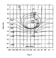
- Fig 4 the Nichols plot is shown when a PID controller is used.
- the total energy response signal contains a frequency component with twice the network frequency. This component can be removed from the controller response using a notch filter. Further it is advisable to assume that a delay occurs in the measured total energy (total capacitor voltage).
- Fig 5 shows the corresponding Nicols's diagram where the notch filter and the time delay have been included.
- Fig 6 shows the simulation result at a step in the reference for the total energy in the converter leg.
- Fig 7 shows the simulation result when the current changes from 0.1 pu to 1.0 pu in the converter leg.
- the products of the cosine functions in (A39) are DC quantities and terms with the double network frequency.
- a proportional controller is sufficient to control the balance between the energies as the function is indeed just an integrator.
- the measured difference energy has a strong fundamental frequency component, which should be eliminated in the response to the regulator.
- F ⁇ s K P ⁇ s 2 + ⁇ 1 2 s 2 + 2 ⁇ ⁇ ⁇ ⁇ 1 + ⁇ 1 2
- Fig 5 shows that the closed loop for the energy controller has unity gain up to about 300 rad/s and that it amplifies frequencies in the range 100 - 200 rad/s with more than 3 dB. Therefore the gain in the balance controller has been kept low for these frequencies in order to avoid interaction between the two controllers.
- the aim of the investigation is to describe an M2C system where the modulation operates in open-loop mode.
- the meaning of the name "open-loop" in this context is that the modulation system does not measure the total voltage of the capacitors in the phase leg arms. Rather these total voltages are estimated in run-time using the desired AC emf and the measured AC current.
- the reference for the inserted arm voltages are obtained assuming that the instantaneous AC emf and AC current are steady state values. Further it is assumed that a voltage sharing system is provided to distribute the total arm voltage in each arm evenly between all modules that constitute the arm.
Landscapes
- Engineering & Computer Science (AREA)
- Power Engineering (AREA)
- Inverter Devices (AREA)
- Rectifiers (AREA)
Claims (8)
- Procédé de calcul d'indices d'insertion pour une branche de phase d'un convertisseur à plusieurs niveaux modulaire continu-alternatif, le convertisseur comprenant une branche de phase entre des barres communes de source de courant continu supérieure et inférieure pour chaque phase, chaque branche de phase comprenant deux bras connectés en série, dans lequel une sortie de courant alternatif pour chaque branche de phase est connectée entre ses deux bras connectés en série, dans lequel chaque bras comprend un certain nombre de sous-modules, dans lequel chaque sous-module peut être dans un état de contournement ou un mode d'insertion de tension, l'indice d'insertion comprenant des données représentant la partie de sous-modules disponibles qui doivent être dans le mode d'insertion de tension pour un bras particulier, le procédé comprenant les étapes consistant à :calculer une tension de bras souhaitée pour un bras supérieur connecté à la barre commune de source de courant continu supérieure et un bras inférieur connecté à la barre commune de source de courant continu inférieure,obtenir des valeurs représentant des tensions de bras totales réelles dans le bras supérieur et le bras inférieur, respectivement, etcalculer des indices d'insertion pour les bras supérieur et inférieur, respectivement, en utilisant la tension de bras respective souhaitée et la valeur respective représentant la tension totale de bras réelle ;dans lequel l'étape de calcul de tensions de bras souhaitées pour une branche de phase consiste à calculer
 pour le bras supérieur, et à calculer
 pour le bras inférieur, où uCU(t) représente une tension de bras supérieure souhaitée, où uCL(T) représente une tension de bras inférieur souhaitée, uD représente une tension entre les barres communes de source de courant continu supérieure et inférieure, ev(t) représente une tension de sortie alternative interne de référence etudiff(t) représente une tension de commande pour commander un courant passant à travers l'ensemble de la branche de phase, et à calculer
 où udiff1(t) représente une tension obtenue en sommant l'énergie dans les bras de la branche et udiff2 (t) représente une tension obtenue en calculant une différence d'énergie entre les bras de la branche.
 - Procédé selon la revendication 1, dans lequel l'étape consistant à obtenir une valeur représentant la tension de bras réelle consiste à calculer

où ûdiff2 représente une différence entre l'énergie de bras supérieur totale et l'énergie de bras inférieur totale, ω1 représente la vitesse angulaire de la fréquence du réseau et ψ représente l'angle donné par ψ = ∠(R + jω1L), où R représente la résistance du bras du convertisseur et L représente de l'inductance du bras du convertisseur. - Procédé de calcul d'indices d'insertion pour une branche de phase d'un convertisseur à plusieurs niveaux modulaire continu-alternatif, le convertisseur comprenant une branche de phase entre des barres communes de source de courant continu supérieure et inférieure pour chaque phase, chaque branche de phase comprenant deux bras connectés en série, dans lequel une sortie de courant alternatif pour chaque branche de phase est connectée entre ses deux bras connectés en série, dans lequel chaque bras comprend un certain nombre de sous-modules, dans lequel chaque sous-module peut être dans un état de contournement ou un mode d'insertion de tension, l'indice d'insertion comprenant des données représentant la partie de sous-modules disponibles qui doivent être dans le mode d'insertion de tension pour un bras particulier, le procédé comprenant les étapes consistant à:calculer une tension de bras souhaitée pour un bras supérieur connecté à la barre commune de source de courant continu supérieure et un bras inférieur connecté à la barre commune de source de courant continu inférieure,obtenir des valeurs représentant des tensions de bras totales réelles, dans le bras supérieur et le bras inférieur, respectivement, etcalculer des indices d'insertion pour les bras supérieur et inférieur, respectivement, en utilisant la tension de bras respective souhaitée et la valeur respective représentant la tension de bras réelle totale ;dans lequel l'étape consistant à calculer des tensions de bras souhaitées pour une branche de phase consiste à calculer
 pour le bras supérieur, et à calculer
 pour le bras inférieur, où uCU(t) représente une tension de bras supérieure souhaitée, où uCL(t) représente une tension de bras inférieur souhaitée, uD représente une tension entre les barres communes de source de courant continu supérieure et inférieure, ev(t) représente une tension de sortie alternative interne de référence etudiff(t) représente une tension de commande pour commander un courant passant à travers l'ensemble de la branche de phase,dans lequel l'étape consistant à obtenir des valeurs représentant des tensions de bras réelles consiste à:calculer
 calculer

- Procédé selon la revendication 3, dans lequel l'étape consistant à obtenir une valeur représentant la tension de bras réelle consiste à calculer

- Procédé selon l'une quelconque des revendications 1 ou 2, dans lequel l'étape consistant à obtenir une valeur représentant une tension de bras totale réelle consiste à mesurer des tensions des sous-modules du bras et à sommer ces tensions mesurées.
- Procédé selon l'une quelconque des revendications précédentes, dans lequel l'indice d'insertion comprend des données représentant une direction de la tension insérée.
- Appareil de calcul d'indices d'insertion pour une branche de phase d'un convertisseur à plusieurs niveaux modulaire continu-alternatif, le convertisseur comprenant une branche de phase entre des barres communes de source de courant continu supérieure et inférieure pour chaque phase, chaque branche de phase comprenant deux bras connectés en série, dans lequel une sortie de courant alternatif pour chaque branche de phase est connectée entre ses deux bras connectés en série, dans lequel chaque bras comprend un certain nombre de sous-modules, dans lequel chaque sous-module peut être dans un état de contournement ou un mode d'insertion de tension, l'indice d'insertion comprenant des données représentant la partie de sous-modules disponibles qui doivent être dans le mode d'insertion de tension pour un bras particulier, et l'appareil comprend :une unité de commande conçue pour calculer une tension de bras souhaitée pour un bras supérieur connecté à la barre commune de source de courant continu supérieure et un bras inférieur connecté à la barre commune de source de courant continu inférieure, pour obtenir des valeurs représentant des tensions de bras totales réelles dans le bras supérieur et le bras inférieur, respectivement, et pour calculer des indices d'insertion pour les bras supérieur et inférieur, respectivement, en utilisant la tension de bras souhaitée respective et la valeur respective représentant la tension de bras totale réelle;dans lequel le calcul de tensions de bras souhaitées pour une branche de phase consiste à calculer
 pour le bras supérieur, et à calculer
 pour le bras inférieur, où uCU(t) représente la tension de bras supérieure souhaitée, uCL(t) représente la tension de bras inférieure souhaitée, uD représente une tension entre les barres communes de source de courant continu supérieure et inférieure, ev(t) représente une tension de sortie alternative de référence interne etudiff(t) représente une tension de commande pour commander un courant passant à travers l'ensemble de la branche de phase, et calculer
 où udiffi(t) représente une tension obtenue en sommant l'énergie dans les bras de la branche et udiff2 (t) représente une tension obtenue en calculant une différence d'énergie entre les bras de la branche.
 - Appareil de calcul d'indices d'insertion pour une branche de phase d'un convertisseur à plusieurs niveaux modulaire continu-alternatif, le convertisseur comprenant une branche de phase entre des barres communes de source de courant continu supérieure et inférieure pour chaque phase, chaque branche de phase comprenant deux bras connectés en série, dans lequel une sortie de courant alternatif pour chaque branche de phase est connectée entre ses deux bras connectés en série, dans lequel chaque bras comprend un certain nombre de sous-modules, dans lequel chaque sous-module peut être dans un état de contournement ou un mode d'insertion de tension, l'indice d'insertion comprenant des données représentant la partie de sous-modules disponibles qui doivent être dans un mode d'insertion de tension pour un bras particulier, et l'appareil comprend :une unité de commande conçue pour calculer une tension de bras souhaitée pour un bras supérieur connecté à la barre commune de source de courant continu supérieure et un bras inférieur connecté à la barre commune de source de courant continu inférieure, pour obtenir des valeurs représentant des tensions de bras totales réelles dans le bras supérieur et le bras inférieur, respectivement, et pour calculer des indices d'insertion pour les bras supérieur et inférieur, respectivement, en utilisant la tension de bras respective souhaitée et la valeur respective représentant la tension de bras totale réelle ;dans lequel le calcul de tensions de bras souhaitées pour une branche de phase consiste à calculer
 pour le bras supérieur, et à calculer
 udiff(t) représente une tension de commande pour commander un courant passant à travers l'ensemble de la branche de phase,dans lequel l'étape consistant à obtenir des valeurs représentant des tensions de bras réelles consiste à:calculer
 calculer

Applications Claiming Priority (2)
| Application Number | Priority Date | Filing Date | Title |
|---|---|---|---|
| US23985909P | 2009-09-04 | 2009-09-04 | |
| PCT/EP2010/062923 WO2011026927A1 (fr) | 2009-09-04 | 2010-09-03 | Procédé et appareil destinés à calculer des indices d'insertion pour un convertisseur modulaire à niveaux multiples |
Publications (2)
| Publication Number | Publication Date |
|---|---|
| EP2474087A1 EP2474087A1 (fr) | 2012-07-11 |
| EP2474087B1 true EP2474087B1 (fr) | 2015-05-20 |
Family
ID=43428489
Family Applications (1)
| Application Number | Title | Priority Date | Filing Date |
|---|---|---|---|
| EP20100768192 Active EP2474087B1 (fr) | 2009-09-04 | 2010-09-03 | Procédé et appareil destinés à calculer des indices d'insertion pour un convertisseur modulaire à niveaux multiples |
Country Status (7)
| Country | Link |
|---|---|
| US (1) | US8374810B2 (fr) |
| EP (1) | EP2474087B1 (fr) |
| CN (1) | CN102577073B (fr) |
| AU (1) | AU2010291222B2 (fr) |
| CA (1) | CA2772713C (fr) |
| MX (1) | MX2012002714A (fr) |
| WO (1) | WO2011026927A1 (fr) |
Families Citing this family (20)
| Publication number | Priority date | Publication date | Assignee | Title |
|---|---|---|---|---|
| EP2474087B1 (fr) * | 2009-09-04 | 2015-05-20 | ABB Technology AG | Procédé et appareil destinés à calculer des indices d'insertion pour un convertisseur modulaire à niveaux multiples |
| CN102403916B (zh) * | 2011-11-04 | 2014-10-22 | 华北电力大学 | 一种仿真提速电路的设计方法 |
| EP2756588A1 (fr) * | 2011-11-14 | 2014-07-23 | Siemens Aktiengesellschaft | Convertisseur modulaire |
| CN103095167B (zh) * | 2012-12-13 | 2014-12-03 | 国网智能电网研究院 | 一种三相模块化多电平换流器能量平衡控制方法 |
| CN104283432B (zh) | 2013-07-03 | 2017-12-26 | 通用电气公司 | 联合共模电压注入系统和方法 |
| CN103427609B (zh) * | 2013-07-30 | 2015-06-17 | 浙江大学 | 一种mmc的谐波特性解析方法 |
| DE102015004603A1 (de) * | 2015-04-09 | 2016-10-13 | Siltectra Gmbh | Kombiniertes Waferherstellungsverfahren mit Laserbehandlung und temperaturinduzierten Spannungen |
| FR3039940B1 (fr) * | 2015-08-03 | 2017-08-11 | Inst Supergrid | Capacite virtuelle |
| CN105337522B (zh) * | 2015-11-03 | 2018-05-25 | 湖南大学 | 一种模块化多电平换流器的双载波调制方法 |
| US10460057B2 (en) * | 2015-11-10 | 2019-10-29 | Wei Li | Apparatus and method for modelling a modular multilevel converter in an electronic simulator |
| CN105406748B (zh) * | 2015-12-10 | 2017-09-19 | 湖南大学 | 一种抑制模块化多电平变流器输出电流谐波的控制方法 |
| CN105553310B (zh) * | 2015-12-31 | 2017-11-21 | 湖南大学 | 一种模块化多电平换流器的低调制度控制方法 |
| US10924029B2 (en) | 2016-09-01 | 2021-02-16 | Abb Power Grids Switzerland Ag | Circulating current control in a modular multilevel voltage source converter |
| CN106452043B (zh) * | 2016-12-01 | 2019-05-07 | 南京南瑞继保电气有限公司 | 一种子模块分布式充电方法 |
| FR3068842B1 (fr) * | 2017-07-07 | 2022-03-04 | Inst Supergrid | Convertisseur muni d'un module de gestion de l'energie en partie alternative |
| CN107681886B (zh) * | 2017-10-12 | 2020-08-04 | 上海交通大学 | 自平衡非隔离型模块化多电平dc-dc变换器 |
| WO2019140584A1 (fr) * | 2018-01-18 | 2019-07-25 | 华北电力大学 | Procédé de suppression adaptative en ligne d'oscillation haute fréquence provoquée par un courant continu flexible |
| CN110350798B (zh) * | 2019-06-27 | 2020-10-23 | 浙江大学 | 模块化多电平谐振变换器的桥臂间均压控制方法 |
| CN115498909B (zh) * | 2022-11-07 | 2024-09-17 | 国网智能电网研究院有限公司 | 光伏并网系统、光伏换流器的子模块均衡控制方法及系统 |
| EP4687250A1 (fr) | 2024-08-02 | 2026-02-04 | Hitachi Energy Ltd | Suppression de courant d'inversion transitoire du côté d'un système de transmission en courant continu à haute tension |
Family Cites Families (5)
| Publication number | Priority date | Publication date | Assignee | Title |
|---|---|---|---|---|
| SU1078342A1 (ru) * | 1982-03-15 | 1984-03-07 | Особое Конструкторское Бюро Средств Автоматизации И Контроля И Электроэрозионного Оборудования | Способ измерени электрических величин |
| DE20122923U1 (de) | 2001-01-24 | 2010-02-25 | Siemens Aktiengesellschaft | Stromrichterschaltungen mit verteilten Energiespeichern |
| CN1625037A (zh) * | 2004-12-10 | 2005-06-08 | 华中科技大学 | 级联型多电平逆变器 |
| EP2100364B1 (fr) * | 2006-12-08 | 2018-09-12 | Siemens Aktiengesellschaft | Commande d'un convertisseur modulaire avec des accumulateurs d'énergie répartis |
| EP2474087B1 (fr) * | 2009-09-04 | 2015-05-20 | ABB Technology AG | Procédé et appareil destinés à calculer des indices d'insertion pour un convertisseur modulaire à niveaux multiples |
-
2010
- 2010-09-03 EP EP20100768192 patent/EP2474087B1/fr active Active
- 2010-09-03 AU AU2010291222A patent/AU2010291222B2/en active Active
- 2010-09-03 WO PCT/EP2010/062923 patent/WO2011026927A1/fr not_active Ceased
- 2010-09-03 CA CA2772713A patent/CA2772713C/fr active Active
- 2010-09-03 CN CN201080046819.1A patent/CN102577073B/zh active Active
- 2010-09-03 MX MX2012002714A patent/MX2012002714A/es active IP Right Grant
-
2012
- 2012-03-05 US US13/412,393 patent/US8374810B2/en active Active
Also Published As
| Publication number | Publication date |
|---|---|
| MX2012002714A (es) | 2012-04-19 |
| AU2010291222B2 (en) | 2015-07-09 |
| EP2474087A1 (fr) | 2012-07-11 |
| CA2772713C (fr) | 2018-06-19 |
| AU2010291222A1 (en) | 2012-03-22 |
| CA2772713A1 (fr) | 2011-03-10 |
| CN102577073A (zh) | 2012-07-11 |
| WO2011026927A1 (fr) | 2011-03-10 |
| US20120191391A1 (en) | 2012-07-26 |
| CN102577073B (zh) | 2015-05-20 |
| US8374810B2 (en) | 2013-02-12 |
Similar Documents
| Publication | Publication Date | Title |
|---|---|---|
| EP2474087B1 (fr) | Procédé et appareil destinés à calculer des indices d'insertion pour un convertisseur modulaire à niveaux multiples | |
| Vilathgamuwa et al. | Performance improvement of the dynamic voltage restorer with closed-loop load voltage and current-mode control | |
| Saïd-Romdhane et al. | Robust active damping methods for LCL filter-based grid-connected converters | |
| Garcia et al. | Observer-based pulsed signal injection for grid impedance estimation in three-phase systems | |
| de Araujo Ribeiro et al. | A robust adaptive control strategy of active power filters for power-factor correction, harmonic compensation, and balancing of nonlinear loads | |
| Li et al. | Design and comparison of high performance stationary-frame controllers for DVR implementation | |
| Dannehl et al. | Investigation of active damping approaches for PI-based current control of grid-connected pulse width modulation converters with LCL filters | |
| de Araujo Ribeiro et al. | A robust DC-link voltage control strategy to enhance the performance of shunt active power filters without harmonic detection schemes | |
| Dannehl et al. | Limitations of voltage-oriented PI current control of grid-connected PWM rectifiers with $ LCL $ filters | |
| Wessels et al. | Active damping of LCL-filter resonance based on virtual resistor for PWM rectifiers—Stability analysis with different filter parameters | |
| Antonopoulos et al. | On dynamics and voltage control of the modular multilevel converter | |
| Miveh et al. | An Improved Control Strategy for a Four‐Leg Grid‐Forming Power Converter under Unbalanced Load Conditions | |
| Hogan et al. | A rapid prototyping tool for load and source emulation in a microgrid test laboratory | |
| Khalid et al. | A novel control scheme for three-phase seven-level packed U-Cell based DSTATCOM | |
| Pouresmaeil et al. | Instantaneous active and reactive current control technique of shunt active power filter based on the three‐level NPC inverter | |
| Durgante et al. | Combined active damping with adaptive current control for converters with LCL filters | |
| Singh et al. | Control of DSTATCOM using IcosΦ algorithm | |
| Harnefors et al. | Passivity-based stabilization of voltage-source converters equipped with LCL input filters | |
| Mishra et al. | A proportional resonator-based control scheme to suppress AC components in circulating current of modulator multilevel converter | |
| Rawat et al. | Comparison of two current harmonic elimination methods for improving supply side current waveforms | |
| Sheeja et al. | BESS based voltage and frequency controller for stand alone wind energy conversion system employing PMSG | |
| Kabiri et al. | DigSILENT modelling of power electronic converters for distributed generation networks | |
| Franke et al. | Analysis of control strategies for a 3 phase 4 wire topology for transformerless solar inverters | |
| Le Claire et al. | A simple feedback for parallel operation of current controlled inverters involved in UPS | |
| Nazib et al. | High quality voltage regulation of single phase autonomous microgrids under nonlinear load conditions |
Legal Events
| Date | Code | Title | Description |
|---|---|---|---|
| PUAI | Public reference made under article 153(3) epc to a published international application that has entered the european phase |
Free format text: ORIGINAL CODE: 0009012 |
|
| 17P | Request for examination filed |
Effective date: 20120404 |
|
| AK | Designated contracting states |
Kind code of ref document: A1 Designated state(s): AL AT BE BG CH CY CZ DE DK EE ES FI FR GB GR HR HU IE IS IT LI LT LU LV MC MK MT NL NO PL PT RO SE SI SK SM TR |
|
| DAX | Request for extension of the european patent (deleted) | ||
| GRAP | Despatch of communication of intention to grant a patent |
Free format text: ORIGINAL CODE: EPIDOSNIGR1 |
|
| INTG | Intention to grant announced |
Effective date: 20150209 |
|
| GRAS | Grant fee paid |
Free format text: ORIGINAL CODE: EPIDOSNIGR3 |
|
| GRAA | (expected) grant |
Free format text: ORIGINAL CODE: 0009210 |
|
| AK | Designated contracting states |
Kind code of ref document: B1 Designated state(s): AL AT BE BG CH CY CZ DE DK EE ES FI FR GB GR HR HU IE IS IT LI LT LU LV MC MK MT NL NO PL PT RO SE SI SK SM TR |
|
| REG | Reference to a national code |
Ref country code: GB Ref legal event code: FG4D |
|
| REG | Reference to a national code |
Ref country code: CH Ref legal event code: EP |
|
| REG | Reference to a national code |
Ref country code: AT Ref legal event code: REF Ref document number: 728190 Country of ref document: AT Kind code of ref document: T Effective date: 20150615 |
|
| REG | Reference to a national code |
Ref country code: IE Ref legal event code: FG4D |
|
| REG | Reference to a national code |
Ref country code: DE Ref legal event code: R096 Ref document number: 602010024793 Country of ref document: DE |
|
| REG | Reference to a national code |
Ref country code: SE Ref legal event code: TRGR |
|
| REG | Reference to a national code |
Ref country code: FR Ref legal event code: PLFP Year of fee payment: 6 |
|
| REG | Reference to a national code |
Ref country code: AT Ref legal event code: MK05 Ref document number: 728190 Country of ref document: AT Kind code of ref document: T Effective date: 20150520 |
|
| REG | Reference to a national code |
Ref country code: LT Ref legal event code: MG4D |
|
| REG | Reference to a national code |
Ref country code: NL Ref legal event code: MP Effective date: 20150520 |
|
| PG25 | Lapsed in a contracting state [announced via postgrant information from national office to epo] |
Ref country code: FI Free format text: LAPSE BECAUSE OF FAILURE TO SUBMIT A TRANSLATION OF THE DESCRIPTION OR TO PAY THE FEE WITHIN THE PRESCRIBED TIME-LIMIT Effective date: 20150520 Ref country code: ES Free format text: LAPSE BECAUSE OF FAILURE TO SUBMIT A TRANSLATION OF THE DESCRIPTION OR TO PAY THE FEE WITHIN THE PRESCRIBED TIME-LIMIT Effective date: 20150520 Ref country code: NO Free format text: LAPSE BECAUSE OF FAILURE TO SUBMIT A TRANSLATION OF THE DESCRIPTION OR TO PAY THE FEE WITHIN THE PRESCRIBED TIME-LIMIT Effective date: 20150820 Ref country code: LT Free format text: LAPSE BECAUSE OF FAILURE TO SUBMIT A TRANSLATION OF THE DESCRIPTION OR TO PAY THE FEE WITHIN THE PRESCRIBED TIME-LIMIT Effective date: 20150520 Ref country code: PT Free format text: LAPSE BECAUSE OF FAILURE TO SUBMIT A TRANSLATION OF THE DESCRIPTION OR TO PAY THE FEE WITHIN THE PRESCRIBED TIME-LIMIT Effective date: 20150921 Ref country code: HR Free format text: LAPSE BECAUSE OF FAILURE TO SUBMIT A TRANSLATION OF THE DESCRIPTION OR TO PAY THE FEE WITHIN THE PRESCRIBED TIME-LIMIT Effective date: 20150520 |
|
| PG25 | Lapsed in a contracting state [announced via postgrant information from national office to epo] |
Ref country code: GR Free format text: LAPSE BECAUSE OF FAILURE TO SUBMIT A TRANSLATION OF THE DESCRIPTION OR TO PAY THE FEE WITHIN THE PRESCRIBED TIME-LIMIT Effective date: 20150821 Ref country code: LV Free format text: LAPSE BECAUSE OF FAILURE TO SUBMIT A TRANSLATION OF THE DESCRIPTION OR TO PAY THE FEE WITHIN THE PRESCRIBED TIME-LIMIT Effective date: 20150520 Ref country code: BG Free format text: LAPSE BECAUSE OF FAILURE TO SUBMIT A TRANSLATION OF THE DESCRIPTION OR TO PAY THE FEE WITHIN THE PRESCRIBED TIME-LIMIT Effective date: 20150820 Ref country code: AT Free format text: LAPSE BECAUSE OF FAILURE TO SUBMIT A TRANSLATION OF THE DESCRIPTION OR TO PAY THE FEE WITHIN THE PRESCRIBED TIME-LIMIT Effective date: 20150520 Ref country code: IS Free format text: LAPSE BECAUSE OF FAILURE TO SUBMIT A TRANSLATION OF THE DESCRIPTION OR TO PAY THE FEE WITHIN THE PRESCRIBED TIME-LIMIT Effective date: 20150920 |
|
| PG25 | Lapsed in a contracting state [announced via postgrant information from national office to epo] |
Ref country code: DK Free format text: LAPSE BECAUSE OF FAILURE TO SUBMIT A TRANSLATION OF THE DESCRIPTION OR TO PAY THE FEE WITHIN THE PRESCRIBED TIME-LIMIT Effective date: 20150520 Ref country code: EE Free format text: LAPSE BECAUSE OF FAILURE TO SUBMIT A TRANSLATION OF THE DESCRIPTION OR TO PAY THE FEE WITHIN THE PRESCRIBED TIME-LIMIT Effective date: 20150520 |
|
| REG | Reference to a national code |
Ref country code: DE Ref legal event code: R097 Ref document number: 602010024793 Country of ref document: DE |
|
| PG25 | Lapsed in a contracting state [announced via postgrant information from national office to epo] |
Ref country code: PL Free format text: LAPSE BECAUSE OF FAILURE TO SUBMIT A TRANSLATION OF THE DESCRIPTION OR TO PAY THE FEE WITHIN THE PRESCRIBED TIME-LIMIT Effective date: 20150520 Ref country code: SK Free format text: LAPSE BECAUSE OF FAILURE TO SUBMIT A TRANSLATION OF THE DESCRIPTION OR TO PAY THE FEE WITHIN THE PRESCRIBED TIME-LIMIT Effective date: 20150520 Ref country code: RO Free format text: LAPSE BECAUSE OF NON-PAYMENT OF DUE FEES Effective date: 20150520 Ref country code: CZ Free format text: LAPSE BECAUSE OF FAILURE TO SUBMIT A TRANSLATION OF THE DESCRIPTION OR TO PAY THE FEE WITHIN THE PRESCRIBED TIME-LIMIT Effective date: 20150520 |
|
| PLBE | No opposition filed within time limit |
Free format text: ORIGINAL CODE: 0009261 |
|
| STAA | Information on the status of an ep patent application or granted ep patent |
Free format text: STATUS: NO OPPOSITION FILED WITHIN TIME LIMIT |
|
| 26N | No opposition filed |
Effective date: 20160223 |
|
| PG25 | Lapsed in a contracting state [announced via postgrant information from national office to epo] |
Ref country code: LU Free format text: LAPSE BECAUSE OF FAILURE TO SUBMIT A TRANSLATION OF THE DESCRIPTION OR TO PAY THE FEE WITHIN THE PRESCRIBED TIME-LIMIT Effective date: 20150903 Ref country code: MC Free format text: LAPSE BECAUSE OF FAILURE TO SUBMIT A TRANSLATION OF THE DESCRIPTION OR TO PAY THE FEE WITHIN THE PRESCRIBED TIME-LIMIT Effective date: 20150520 Ref country code: IT Free format text: LAPSE BECAUSE OF FAILURE TO SUBMIT A TRANSLATION OF THE DESCRIPTION OR TO PAY THE FEE WITHIN THE PRESCRIBED TIME-LIMIT Effective date: 20150520 |
|
| REG | Reference to a national code |
Ref country code: CH Ref legal event code: PL |
|
| PG25 | Lapsed in a contracting state [announced via postgrant information from national office to epo] |
Ref country code: SI Free format text: LAPSE BECAUSE OF FAILURE TO SUBMIT A TRANSLATION OF THE DESCRIPTION OR TO PAY THE FEE WITHIN THE PRESCRIBED TIME-LIMIT Effective date: 20150520 |
|
| REG | Reference to a national code |
Ref country code: IE Ref legal event code: MM4A |
|
| PG25 | Lapsed in a contracting state [announced via postgrant information from national office to epo] |
Ref country code: CH Free format text: LAPSE BECAUSE OF NON-PAYMENT OF DUE FEES Effective date: 20150930 Ref country code: IE Free format text: LAPSE BECAUSE OF NON-PAYMENT OF DUE FEES Effective date: 20150903 Ref country code: LI Free format text: LAPSE BECAUSE OF NON-PAYMENT OF DUE FEES Effective date: 20150930 |
|
| PG25 | Lapsed in a contracting state [announced via postgrant information from national office to epo] |
Ref country code: BE Free format text: LAPSE BECAUSE OF FAILURE TO SUBMIT A TRANSLATION OF THE DESCRIPTION OR TO PAY THE FEE WITHIN THE PRESCRIBED TIME-LIMIT Effective date: 20150520 |
|
| REG | Reference to a national code |
Ref country code: FR Ref legal event code: PLFP Year of fee payment: 7 |
|
| REG | Reference to a national code |
Ref country code: DE Ref legal event code: R081 Ref document number: 602010024793 Country of ref document: DE Owner name: HITACHI ENERGY SWITZERLAND AG, CH Free format text: FORMER OWNER: ABB TECHNOLOGY AG, ZUERICH, CH Ref country code: DE Ref legal event code: R081 Ref document number: 602010024793 Country of ref document: DE Owner name: ABB SCHWEIZ AG, CH Free format text: FORMER OWNER: ABB TECHNOLOGY AG, ZUERICH, CH Ref country code: DE Ref legal event code: R081 Ref document number: 602010024793 Country of ref document: DE Owner name: ABB POWER GRIDS SWITZERLAND AG, CH Free format text: FORMER OWNER: ABB TECHNOLOGY AG, ZUERICH, CH |
|
| PG25 | Lapsed in a contracting state [announced via postgrant information from national office to epo] |
Ref country code: MT Free format text: LAPSE BECAUSE OF FAILURE TO SUBMIT A TRANSLATION OF THE DESCRIPTION OR TO PAY THE FEE WITHIN THE PRESCRIBED TIME-LIMIT Effective date: 20150520 |
|
| PG25 | Lapsed in a contracting state [announced via postgrant information from national office to epo] |
Ref country code: SM Free format text: LAPSE BECAUSE OF FAILURE TO SUBMIT A TRANSLATION OF THE DESCRIPTION OR TO PAY THE FEE WITHIN THE PRESCRIBED TIME-LIMIT Effective date: 20150520 Ref country code: HU Free format text: LAPSE BECAUSE OF FAILURE TO SUBMIT A TRANSLATION OF THE DESCRIPTION OR TO PAY THE FEE WITHIN THE PRESCRIBED TIME-LIMIT; INVALID AB INITIO Effective date: 20100903 |
|
| PG25 | Lapsed in a contracting state [announced via postgrant information from national office to epo] |
Ref country code: NL Free format text: LAPSE BECAUSE OF FAILURE TO SUBMIT A TRANSLATION OF THE DESCRIPTION OR TO PAY THE FEE WITHIN THE PRESCRIBED TIME-LIMIT Effective date: 20150520 Ref country code: CY Free format text: LAPSE BECAUSE OF FAILURE TO SUBMIT A TRANSLATION OF THE DESCRIPTION OR TO PAY THE FEE WITHIN THE PRESCRIBED TIME-LIMIT Effective date: 20150520 |
|
| PG25 | Lapsed in a contracting state [announced via postgrant information from national office to epo] |
Ref country code: TR Free format text: LAPSE BECAUSE OF FAILURE TO SUBMIT A TRANSLATION OF THE DESCRIPTION OR TO PAY THE FEE WITHIN THE PRESCRIBED TIME-LIMIT Effective date: 20150520 |
|
| REG | Reference to a national code |
Ref country code: FR Ref legal event code: PLFP Year of fee payment: 8 |
|
| REG | Reference to a national code |
Ref country code: GB Ref legal event code: 732E Free format text: REGISTERED BETWEEN 20180426 AND 20180502 |
|
| PG25 | Lapsed in a contracting state [announced via postgrant information from national office to epo] |
Ref country code: MK Free format text: LAPSE BECAUSE OF FAILURE TO SUBMIT A TRANSLATION OF THE DESCRIPTION OR TO PAY THE FEE WITHIN THE PRESCRIBED TIME-LIMIT Effective date: 20150520 |
|
| REG | Reference to a national code |
Ref country code: DE Ref legal event code: R084 Ref document number: 602010024793 Country of ref document: DE |
|
| REG | Reference to a national code |
Ref country code: FR Ref legal event code: PLFP Year of fee payment: 9 |
|
| REG | Reference to a national code |
Ref country code: FR Ref legal event code: TP Owner name: ABB SCHWEIZ AG, CH Effective date: 20180912 |
|
| PG25 | Lapsed in a contracting state [announced via postgrant information from national office to epo] |
Ref country code: AL Free format text: LAPSE BECAUSE OF FAILURE TO SUBMIT A TRANSLATION OF THE DESCRIPTION OR TO PAY THE FEE WITHIN THE PRESCRIBED TIME-LIMIT Effective date: 20150520 |
|
| REG | Reference to a national code |
Ref country code: DE Ref legal event code: R081 Ref document number: 602010024793 Country of ref document: DE Owner name: HITACHI ENERGY SWITZERLAND AG, CH Free format text: FORMER OWNER: ABB SCHWEIZ AG, BADEN, CH Ref country code: DE Ref legal event code: R082 Ref document number: 602010024793 Country of ref document: DE Representative=s name: DENNEMEYER & ASSOCIATES RECHTSANWALTSGESELLSCH, DE Ref country code: DE Ref legal event code: R081 Ref document number: 602010024793 Country of ref document: DE Owner name: HITACHI ENERGY LTD, CH Free format text: FORMER OWNER: ABB SCHWEIZ AG, BADEN, CH Ref country code: DE Ref legal event code: R082 Ref document number: 602010024793 Country of ref document: DE Representative=s name: DENNEMEYER & ASSOCIATES S.A., DE Ref country code: DE Ref legal event code: R081 Ref document number: 602010024793 Country of ref document: DE Owner name: ABB POWER GRIDS SWITZERLAND AG, CH Free format text: FORMER OWNER: ABB SCHWEIZ AG, BADEN, CH |
|
| REG | Reference to a national code |
Ref country code: GB Ref legal event code: 732E Free format text: REGISTERED BETWEEN 20211104 AND 20211110 |
|
| REG | Reference to a national code |
Ref country code: DE Ref legal event code: R081 Ref document number: 602010024793 Country of ref document: DE Owner name: HITACHI ENERGY SWITZERLAND AG, CH Free format text: FORMER OWNER: ABB POWER GRIDS SWITZERLAND AG, BADEN, CH Ref country code: DE Ref legal event code: R081 Ref document number: 602010024793 Country of ref document: DE Owner name: HITACHI ENERGY LTD, CH Free format text: FORMER OWNER: ABB POWER GRIDS SWITZERLAND AG, BADEN, CH |
|
| P01 | Opt-out of the competence of the unified patent court (upc) registered |
Effective date: 20230527 |
|
| REG | Reference to a national code |
Ref country code: DE Ref legal event code: R082 Ref document number: 602010024793 Country of ref document: DE Representative=s name: DENNEMEYER & ASSOCIATES RECHTSANWALTSGESELLSCH, DE Ref country code: DE Ref legal event code: R082 Ref document number: 602010024793 Country of ref document: DE Representative=s name: DENNEMEYER & ASSOCIATES S.A., DE Ref country code: DE Ref legal event code: R081 Ref document number: 602010024793 Country of ref document: DE Owner name: HITACHI ENERGY LTD, CH Free format text: FORMER OWNER: HITACHI ENERGY SWITZERLAND AG, BADEN, CH |
|
| REG | Reference to a national code |
Ref country code: GB Ref legal event code: 732E Free format text: REGISTERED BETWEEN 20240718 AND 20240724 |
|
| REG | Reference to a national code |
Ref country code: DE Ref legal event code: R082 Ref document number: 602010024793 Country of ref document: DE Representative=s name: DENNEMEYER & ASSOCIATES RECHTSANWALTSGESELLSCH, DE |
|
| PGFP | Annual fee paid to national office [announced via postgrant information from national office to epo] |
Ref country code: DE Payment date: 20250919 Year of fee payment: 16 |
|
| PGFP | Annual fee paid to national office [announced via postgrant information from national office to epo] |
Ref country code: GB Payment date: 20250918 Year of fee payment: 16 |
|
| PGFP | Annual fee paid to national office [announced via postgrant information from national office to epo] |
Ref country code: FR Payment date: 20250922 Year of fee payment: 16 |
|
| PGFP | Annual fee paid to national office [announced via postgrant information from national office to epo] |
Ref country code: SE Payment date: 20250918 Year of fee payment: 16 |