EP2474224B1 - Ruche locale dotée d'un système de contrôle de l'humidité et de la température en son intérieur - Google Patents
Ruche locale dotée d'un système de contrôle de l'humidité et de la température en son intérieur Download PDFInfo
- Publication number
- EP2474224B1 EP2474224B1 EP11000096.5A EP11000096A EP2474224B1 EP 2474224 B1 EP2474224 B1 EP 2474224B1 EP 11000096 A EP11000096 A EP 11000096A EP 2474224 B1 EP2474224 B1 EP 2474224B1
- Authority
- EP
- European Patent Office
- Prior art keywords
- fan
- humidity
- housing
- electronics
- container
- Prior art date
- Legal status (The legal status is an assumption and is not a legal conclusion. Google has not performed a legal analysis and makes no representation as to the accuracy of the status listed.)
- Active
Links
Images


Classifications
-
- A—HUMAN NECESSITIES
- A01—AGRICULTURE; FORESTRY; ANIMAL HUSBANDRY; HUNTING; TRAPPING; FISHING
- A01K—ANIMAL HUSBANDRY; AVICULTURE; APICULTURE; PISCICULTURE; FISHING; REARING OR BREEDING ANIMALS, NOT OTHERWISE PROVIDED FOR; NEW BREEDS OF ANIMALS
- A01K47/00—Beehives
- A01K47/06—Other details of beehives, e.g. ventilating devices, entrances to hives, guards, partitions or bee escapes
Definitions
- the present invention relates to beehives and, in particular, to beehives with a controlled microclimate inside the beehive.
- WO 00/57694 A1 discloses a ventilated bee hive.
- the bee hive comprises an electrically operated ventilation mechanism installed at the top of the hive.
- the hive further comprises openings at the bottom and at side walls. When active, the ventilation mechanism draws in air through the openings and generates an airflow through a confinement of the hive.
- US 159081 A discloses a bee hive.
- the atmosphere within the bee hive in extreme hot weather may be cooled by evaporating water from pans or other proper receptacles placed on the floor of the bee hive.
- honeybees Due to high temperature and dryness, a high percentage of honeybees dies in dry regions, like, e.g., parts of Saudi Arabia during summer. Moreover, eggs of the queen will not hatch if the humidity is too low. This leads to a major loss for local honeybee keepers.
- the present invention solves the problem by a beehive system according to claim 1 and a method according to claim 15.
- the beehive system comprises a housing with at least one ambient condition sensor being adapted to sense an ambient condition in the housing.
- the beehive system comprises a first fan being adapted to generate an air flow in at least a portion of the housing and a container for a liquid having an opening.
- the container is arranged such that the air flow generated by the first fan at least partially passes the opening of the container.
- the beehive system in addition, comprises electronics connected to the ambient condition sensor and to the first fan. The electronics controls the first fan according to the sensed ambient condition.
- the term of the air flow at least partially passing the opening of the container does not necessarily imply the air flow being directed towards the container or the liquid contained therein.
- the air flow may also be directed substantially parallel to a surface of the liquid or to the opening.
- the present invention solves the above problem by providing an air flow inside the housing, which is controlled by the electronics according to a sensed ambient condition in the housing.
- the generated air flow may provide a cooling.
- the air flow passing the opening of the container will lead to an increased evaporation of the liquid.
- the resulting vapor increases the humidity in the housing.
- the first fan is arranged at the opening of the container.
- the air flow is directed over the surface of the liquid in the container. This leads to an improved air exchange in the region above the liquid surface and, thereby, to an improved evaporation of the liquid. Hence, the humidity in the housing may be increased more efficiently.
- the opening of the container is further provided with a barrier which is adapted to let air pass through.
- the barrier prevents dirt and bees from entering the container. Especially when the fan is activated, the generated air flow may drive dirt or bees towards the container.
- the barrier in particular, prevents the bees from being driven into the liquid.
- the barrier comprises a board with holes, a net and/ or a mesh-like structure.
- a board with holes, a net or a mesh-like structure are easy to fabricate and are usually readily available in places where beehives are positioned. Moreover, they allow for an increased air flow through the barrier as compared to permeable membranes, which would otherwise be used, and which may also used in conjunction with the present invention.
- the barrier comprises an aperture and the first fan is arranged in the aperture of the barrier.
- the first fan is arranged in the opening of the container.
- the air flow generated by the first fan is more efficiently directed towards the surface of the liquid. This facilitates evaporation of the liquid and helps to increase the humidity in the housing.
- the first fan generates an air flow which is directed into the housing. The wet air is thus effectively drawn from the container into the housing.
- system further comprises removable frames being arranged in the housing.
- the frames assist the bees building their honeycombs. Providing frames usually leads to the bees building their honeycombs into the frames rather than to other parts of the housing. The honeycombs may easily be retrieved by removing the frames from the housing.
- the system may comprise between 5 and 20, preferably between 6 and 12, more preferably between 6 and 9 and most preferably 7 or 8 removable frames being arranged in the housing.
- these numbers of frames provide frames of a good size for honeybees to build honeycombs into.
- the preferred number of frames leads to larger distances between the frames, such that the air flow can pass between the frames, leading to a better control of the ambient conditions in the housing.
- the removable frames may be arranged above the container.
- the wet air rising from the container passes between the frames.
- the humidity experienced by the bees is efficiently increased.
- the container is placed inside the housing or under the housing.
- Placing the constant container inside the housing has the benefit of protecting the liquid inside the container from external influences like, for example from other animals drinking from the liquid. Moreover, in these embodiments, most of the evaporated liquid passes through the housing.
- the container may further comprise a port for refilling the liquid.
- the housing may further comprise a connecting port that allows access to the port of the container to refill the container.
- the bee hive system further comprises a tube with first and second open ends, the first end of the tube being in communication with the container and the second end being accessible from outside the beehive for refilling the container with liquid.
- This embodiment facilitates refilling the liquid in the container.
- the second end of the tube can easily be used to refill the liquid from outside, e.g., by means of a funnel, which may also be comprised by the bee hive system.
- the first end of the tube may be positioned in the container.
- the tube may further be connected to said port.
- the container further comprises at least one ventilation hole in a top section of the container.
- the first fan draws wet air from the container, the air pressure drops in a top section of the container above the liquid surface. Providing a ventilation hole, air from outside the container is drawn in and is subsequently humidified by the evaporating liquid.
- the ambient condition sensor further comprises at least one humidity sensor and the electronics activates the first fan if the sensed humidity is below a lower humidity threshold.
- the fan when the humidity is too low, the fan is activated, generating an air flow over the surface of the liquid in the container.
- the evaporation of the liquid is enhanced, such that the humidity is increased.
- the first fan moreover, helps to distribute the wet air in the housing.
- the lower humidity threshold may be between 30% and 70 %, preferably between 40 % and 60 % and most preferably between 45 % and 55 % relative humidity.
- the electronics deactivates the first fan if these sensed humidity is above an upper humidity threshold.
- the upper humidity threshold is between 50 % and 90 %, preferably between 60 % and 80 % and most preferably between 65 % and 75 % relative humidity.
- the beehive system further comprises a second fan adapted to generate an air flow in at least a portion of the housing, wherein the second fan is connected to the electronics and the electronics controls the second fan according to the sensed ambient condition.
- This provides a second source for an air flow in the housing. This allows for a more favorable distribution of the air flow in the housing. Moreover, the overall air flow may be increased by using two fans.
- the second fan is arranged in a top section of the housing.
- the first fan being arranged near the bottom of the housing.
- air flows may be generated, both, on the top and the bottom parts of the housing.
- these embodiments have the benefit of allowing an independent control of both air flows.
- the second fan being arranged at the top of the housing, the air flow generated by the second fan does not substantially pass over the surface of the liquid in the container. Hence, activation or deactivation of the second fan has a lower effect on the humidity in the housing than activation or deactivation of the first fan.
- the ambient condition sensor comprises at least one temperature sensor and the electronics activates the first and/or second fan, respectively, if the sensed temperature is above an upper temperature threshold.
- an air flow is generated in the housing if the air is too hot.
- the generated air flow leads to a increased ventilation in the housing.
- a second fan being arranged in a top section of the housing, it is favorable if the electronics activates the second fan if the sensed temperature is above the upward temperature threshold. With the second fan being further away from the container with the liquid, activating the second fan has a lower impact on the humidity, and mostly helps to influence the temperature in the housing.
- the upper temperature threshold may be between 30°C and 38°C, preferably between 32°C and 36°C and most preferably between 33°C and 35°C.
- the electronics may deactivate the first fan and/or the second fan, respectively, if the sensed temperature is below a lower temperature threshold.
- Deactivating the fan will decrease the air flow in the housing. This leads to an increase of the temperature.
- the electronics deactivates the second fan if the sensed temperature is below the lower temperature threshold. This influences the temperature more selectively than controlling the first fan as the first fan due to being close to the liquid also affects the humidity in the housing.
- the lower temperature threshold may be between 28°C and 36°C, preferably between 30°C and 34°C and most preferably between 31°C and 33°C.
- the slower temperature thresholds provide a good surviving condition for honeybees and for the eggs of queen to be hatched.
- the ambient condition sensor comprises two or more humidity sensors and/or temperature sensors.
- the sensed humidity and/or temperature corresponds to an average humidity and/or temperature sensed by the humidity and/or temperature sensors, respectively.
- Using two or more sensors in the housing facilitates sensing the ambient conditions in different parts of the housing. Moreover, the condition in the housing can be sensed more accurately, for example in the case that one sensor is covered by dirt or by bees.
- the two or more humidity sensors are used to obtain an averaged humidity.
- the averaged humidity does not necessarily need to correspond to an arithmetic average. Rather, also a median or a weighted average may be used. Using a median is, in particular, useful if one of the sensors exhibits a failure or is covered. Using a weighted average is helpful to obtain more accurately the ambient condition experienced by the bees, as some of the sensors may be arranged further away from the honeycombs than others. Alternatively, any other kind of averaging may be used.
- the ambient condition sensor comprises at least one humidity sensor and at least one temperature sensor and the electronics controls the first fan and/or the second fan according to the sensed humidity and the sensed temperature.
- both, the humidity and the temperature inside the housing is evaluated. Hence, More detailed information is used to control the first and/or second fan.
- the humidity sensor and the temperature sensor are arranged as a unit to form a dual sensor.
- the dual sensor may comprise any form of attachment between the temperature sensor and the humidity sensor.
- both sensors may be arranged in a common package or may be fixed to the same strip of material. In this embodiment, sensing the humidity and temperature at the same position inside the housing as facilitated. Moreover, placing only one sensor is needed as compared to using separate sensors for humidity and temperature.
- the system further comprises two or more, preferably between 3 and 10 and most preferably between 4 and 8 dual sensors.
- This number of dual sensors has proven to be effective for sensing the ambient conditions in the housing. Using a larger number of sensors may lead to a more accurate mapping of the ambient conditions and the housing, while also the cost and effort for installation and controlling are increased. Using a lower number of sensors may lead to a less precise measurement of the ambient conditions and may, moreover, lead to failure if one or more of the sensors fail.
- the system further comprises an external ambient condition sensor positioned outside the housing and connected to the electronics, wherein the electronics further controls the first and/or second fan according to the ambient condition sensed by the external sensor.
- the fan is controlled based on the ambient condition around the bee hive. If, for example, the outside air is wet due to falling rain, the electronics may direct the second fan to draw in air from the outside to increase the humidity inside the housing rather than directing the first fan to increase evaporation of the liquid. A more detailed control of the conditions in the housing is thus provided.
- the external ambient condition sensor may further comprise a humidity, a temperature and/or a dual sensor.
- the system further comprises powering means being connected to the electronics and/or the fan, wherein the powering means comprises a battery and/or a solar cell.
- This embodiment renders the bee hive system independent from any electronic network. Especially in rural areas, this may be a more reliable supply for electric power than the local electric network. However, power may also be supplied to the electronics and/or the first and/or second fan via an electric network. Still, using a solar cell is especially preferred as the areas, in which the present invention is most useful in terms of controlling the temperature and humidity for the bees, usually have a lot of sunshine.
- the first and/or second fan may have an operating voltage of 12 V DC. This is beneficial for the use of standard car batteries for power supply.
- the first and/or second fan may have an operating voltage of 110 V and/or 220 V AC. As these are typical supply voltages for electrical networks in many parts of the world, the fan can easily be plugged into a standard power socket.
- first and/or second fan and/or the electronics may further comprise means for converting supplied electrical power.
- the electronics may comprise a converter that is adapted to convert any of a 110 V and a 220 V AC supply voltage to 12 V DC voltage which is then used to power the electronics and the first and second fan.
- the converting means may automatically detect the supply voltage and convert it accordingly.
- the electronics may further comprise any type of analog and/or digital and/or mixed-signal electronics.
- the electronics may comprise a digital microcontroller like, e.g., an ASIC.
- the electronics may further comprise at least one analog-to-digital converter for converting signals received from the ambient condition sensor.
- the electronics further comprises a writable memory and, in particular, a re-writable memory to store program data and/or parameter values.
- rules, according to which the electronics controls the first and/or second fan may be updated.
- the electronics may be updated to provide the first and/or the second fan with an increased power, thereby intensifying the air flow, if the number of frames in the housing is increased.
- the electronics can easily be updated without the need to replace any electronic elements.
- the sensed ambient conditions may be stored in the memory for later evaluation.
- the writable memory may, e.g., comprise DRAM, SRAM, flash memory, printer with paper, a hard disk or any other type of electrical, mechanical, magnetic or optical memory. Using a re-writable memory, moreover, allows for re-use of the memory.
- the electronics may further comprise an interface for exchanging a program and/ or a data with an electronic device and/ or a storage medium.
- the data may, for example comprise the sensed humidity and/or temperature values.
- the interface may, e.g., comprise a standard USB interface. Additionally or alternatively, the interface may comprise a different wired or wireless communication standard like a serial or parallel port, LAN, WLAN or Bluetooth, etc. Providing a wireless interface like WLAN or Bluetooth allows the beekeeper to remotely contact the electronics without the need to provide a physical wiring.
- the storage medium may, e.g., comprise a hard disk, a CD-ROM, a DVD or any other electronic, magnetic or optical storage medium.
- the interface may be used to update a program stored in a writable memory of the electronics.
- the program can easily be modified, e.g., if a sensor is added to the system or the first and/or second fan is replaced with another fan having different electrical characteristics like operating voltage without the need to replace the electronics.
- the container is comprised of plastic or wood, in particular waxed wood.
- the container may comprise a metal.
- aluminum is a preferred, as it does not corrode and is easy to process.
- waxed wood is preferred since wood and bee wax are usually readily available in those regions, on which beehives are placed. Moreover, renovation of a worn-out container can easily be done by the beekeeper by re-waxing the container surface. In addition, waxed wood and plastic containers are usually quite cheap.
- the container may comprise a level sensor for sensing the filling level of the liquid in the container.
- the beehive system further comprises a liquid indicator being connected to the level sensor for indicating the liquid filling level.
- the indicator may, e.g., comprise an LCD display or a light indicator.
- the beekeeper can easily check the filling level without the need to look into the container.
- a light indicator may be visible from afar, such that the beekeeper does not need to approach the bee hive to check the filling level.
- the level sensor may further be connected to the electronics. This is especially useful if the electronics comprises an interface for exchanging data with an electronic device. This way, the filling level may easily be indicated to the beekeeper via a standard interface and monitoring means.
- the container may further comprise a sponge. This is beneficial as the sponge is capable of absorbing a larger amount of water.
- the housing further comprises one or more ventilation openings.
- Providing one or more ventilation openings has the benefit of allowing air exchange between the inside and the outside of the housing other than through an entrance opening for the bees. Fresh air may be drawn into or expelled out of the bee hive to affect the temperature and humidity in the bee hive.
- the ventilation openings are arranged in a top section of the housing.
- a second fan which is arranged in a top section of the housing.
- the second fan is arranged close to the ventilation openings, such that the second fan may be used to control the air exchange with the outside.
- the second fan may thus be used to blow in dry air from the outside into the housing or to blow a wet air from inside the housing to the outside.
- the ventilation openings may be arranged in a vertical side wall of the housing.
- the ventilation opening may further comprise a cover for preventing dirt from entering through the ventilation opening.
- the system may comprise more than two fans to provide a more detailed control of the air flow in the housing.
- the fans are connected to and controlled by the electronics.
- the invention provides a method for altering an ambient condition in a bee hive comprising: sensing the ambient condition in the bee hive, and controlling a first fan according to the sensed ambient condition.
- the sensed ambient condition may, in particular, comprise a humidity and/or a temperature.
- altering an ambient condition comprises increasing a humidity and/or lowering a temperature.
- the method may further comprise the step of providing a liquid adjacent to an air flow generated by the first fan. Further aspects disclosed in the context of the bee hive system of the present invention may also be used in conjunction with the above method.
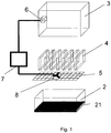
- the beehive system according to a first embodiment of the present invention as shown in Figure 1 comprises a housing 3 and a container 2 which is filled with a liquid 21.
- the housing 3 is adapted to be a put on top of the container 2.
- the housing 3 is in the form of a box, which is open on a bottom side.
- the beehive system moreover, comprises a barrier 5 in the form of a mesh.
- the mesh is a wire mesh with a mesh size adapted to prevent bees from passing through.
- the barrier 5 is adapted to be positioned between the housing 3 and the container 2.
- the barrier 5 defines a plane. It substantially separates the housing 3 from the container 2. In particular, the barrier 5 prevents bees from entering the container 2 from the housing 3.
- first fan 8 In the center of the barrier 5, there is an aperture in which a first fan 8 is arranged.
- the plane of rotation of the first fan 8 is parallel to the plane defined by the barrier 5.
- the first fan 8 is adapted to generate an air flow from the container 2 to the housing 3.
- the barrier comprises a plurality of apertures, and in each aperture, a respective fan is arranged. This leads to air flows being generated at different positions in the plane of the barrier. Ventilation in the housing and distribution of vapor may thus be optimized.
- the beehive system of Figure 1 further comprises electronics 7 to control the first fan 8.
- the electronics 7 is, moreover, connected to an ambient condition sensor 6, which takes the form of a dual sensor for, both, temperature and humidity.
- the ambient condition sensor 6 is arranged on a side wall of the housing 3.
- the electronics 7 controls the first fan 8 according to signals from the ambient condition sensor 6.
- the senor may be placed in other positions in the housing, like, e.g., on an under side of a top cover.
- controlling the first fan 8 may comprise complete activation or deactivation of the first fan 8.
- the first fan 8 either runs on a maximum power or is completely switched off, based on the sensed ambient conditions.
- the electronics 7 may switch on the first fan 8 if the sensed temperature is above 34°C and switch off the first fan 8 if the sensed temperature is below 32°C.
- the electronics 7 may switch on the first fan 8 if the sensed humidity is below 50 % and switch off the first fan 8 if the sensed humidity is above 70 %. In all other cases, the electronics 7 does not change the previous powering state of the first fan 8.
- the electronics 7 may control the first fan 8 to switch to intermediate power values larger than 0 % and lower than 100 %, too.
- both, continuous and discontinuous power values may be used.
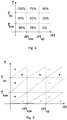
- FIG. 3 shows an example of a control diagram which may be used for the electronics 7.
- a temperature axis (T) and an axis of relative humidity (rH) is shown.
- T temperature axis
- rH relative humidity
- an upper temperature threshold T up and a lower temperature threshold T low are indicated.
- an upper humidity threshold rH up and a lower humidity threshold rH low are shown.
- the diagram illustrates how the electronics 7 controls the first fan 8. E.g., if the sensed temperature is above the upper temperature threshold T up and the sensed humidity is below the lower humidity threshold rH low , the electronics 7 controls the first fan 8 such that the first fan 8 operates at 100 % power.
- the electronics 7 deactivates the first fan 8. In all other scenarios, the electronics 7 controls the first fan 8 such that it operates at the power values indicated in Figure 4 which are between 0 % and 100 %.
- the beehive system also comprises seven frames 4.
- the frames 4 When installed, the frames 4 are arranged in the housing 3.
- the frames 4 are parallel to each other and perpendicular to the barrier 5.
- the air flow generated by the first fan 8 can pass between the frames 4.
- the first fan 8 is arranged below the frames 4.
- FIG. 2 shows a second embodiment of the present invention which is similar to the first embodiment as shown in Figure 1 .
- the embodiment of Figure 2 comprises five ambient condition sensors 61-65.
- all ambient condition sensors 61-65 are dual sensors, i.e. each of the ambient condition sensors 61-65 comprises, both, a humidity sensor and a temperature sensor.
- Each of the ambient condition sensors 61-65 is connected to the electronics 7'.
- the electronics 7' is adapted to control the first fan 8 according to signals generated by the ambient condition sensors 61-65. As each of the ambient condition sensors 61-65 generates, both, a temperature signal and a humidity signal, the electronics 7' controls the fan 8 on the basis of ten signals.
- the electronic 7' evaluates the temperature and humidity signals from the ambient condition sensors 61-65.
- the electronics 7' performs an averaging of the five temperature signals and the five humidity signals, respectively.
- the ambient condition sensors 61-65 are distributed within the housing 3.
- Ambient condition sensor 61 is located in an upper corner of the housing 3.
- Sensors 62, 63,64 are attached to side walls of the housing 3.
- Sensor 65 is positioned in a bottom corner of the housing 3 and is located adjacent to and above the barrier 5.
- the electronics 7' averages the temperature signals and the humidity signals, respectively, for controlling the first fan 8.
- the beehive system further comprises a solar cell 10.
- the solar cell 10 is attached to the top of the housing 3.
- the solar cell 10 is connected to the electronics 7" and generates electrical power for driving the electronics 7" and the fan 8.
- the electronics 7 similarly to the embodiment as shown in Figure 2 , controls the first fan according to the ambient condition signals generated by the sensors 6 which are dual sensors for, both, temperature and humidity. Again, the electronics 7" performs an averaging of the temperature and humidity signals obtained from the dual sensors 6.
- the beehive system of Figure 3 moreover, comprises a second fan 9.
- the second fan 9 is arranged in an opening of a side wall 31 of the housing 3.
- the second fan 9 is also connected to the electronics 7".
- the electronics 7" controls the second fan 9 according to ambient conditions sensed by the sensors 6.
- Figure 5 shows a control map, according to which the electronics 7" may control the first fan 8 and the second fan 9.
- Figure 5 shows a temperature axis and a humidity axis.
- nine regions are shown, defined by upper and lower temperature and humidity thresholds.
- the powering state of the first fan 8 and of the second fan 9 by the electronics 7" is shown.
- the left upper sign in each region indicates the powering of the first fan 8 and the lower right sign indicates the powering of the second fan 9.
- the first fan 8 is activated (+) and the second fan 9 is activated (+).
- the first fan 8 is activated if the sensed humidity is below the lower humidity threshold. This is independent of the sensed temperature. Moreover, the first fan 8 is deactivated if the sensed humidity is above the upper humidity threshold, no matter what the sensed temperature is. Analogously, the second fan 9 is activated if the sensed temperature T is above the upper temperature threshold, independent of the sensed humidity. Moreover, the second fan 9 is deactivated if the sensed temperature T is below the lower temperature threshold independent of the sensed humidity.
Landscapes
- Life Sciences & Earth Sciences (AREA)
- Environmental Sciences (AREA)
- Animal Husbandry (AREA)
- Biodiversity & Conservation Biology (AREA)
- Ventilation (AREA)
- Cold Air Circulating Systems And Constructional Details In Refrigerators (AREA)
Claims (15)
- Système de ruche comprenant
un logement (3)
au moins un capteur de condition ambiante (6 ; 61 à 65) étant adapté pour détecter une condition ambiante dans le logement (3),
un premier ventilateur (8) étant adapté pour générer un flux d'air dans au moins une partie du logement (3),
un équipement électronique (7 ; 7', 7") connecté au capteur de condition ambiante (6 ; 61 à 65) et au premier ventilateur (8),
dans lequel l'équipement électronique (7 ; 7', 7" commande le premier ventilateur (8) en fonction de la condition ambiante détectée, et caractérisé par
un récipient (2) pour un liquide (21) ayant une ouverture,
dans lequel le récipient (2) est agencé de telle sorte que le flux d'air généré par le premier ventilateur (8) franchit au moins partiellement l'ouverture du récipient (2), dans lequel le premier ventilateur (8) est agencé au niveau de l'ouverture du récipient (2), et le récipient (2) est placé à l'intérieur du logement (3) ou sous le logement (3). - Système de ruche selon la revendication 1, dans lequel l'ouverture du récipient (2) est dotée en outre d'une barrière (5) qui est adaptée pour laisser passer l'air à travers,
dans lequel, en particulier, la barrière (5) comprend une planche munie de trous, un filet et/ou une structure de type maille. - Système de ruche selon la revendication 2, dans lequel la barrière (5) comprend en outre une ouverture et dans lequel le premier ventilateur (8) est agencé dans l'ouverture de la barrière (5).
- Système de ruche selon l'une quelconque des revendications précédentes, comprenant en outre des cadres amovibles (4) étant agencés dans le logement (3),
dans lequel, en particulier, le système comprend entre 5 et 20, de préférence, entre 6 et 12, de manière davantage préférée, entre 6 et 9, et de manière préférée entre toutes, 7 ou 8 cadres amovibles (4) étant agencés dans le logement (3), et/ou
dans lequel les cadres amovibles (4) sont agencés au-dessus du récipient (2). - Système de ruche selon l'une quelconque des revendications précédentes, dans lequel le récipient comprend en outre un orifice pour l'introduction du liquide, et/ou dans lequel le système de ruche comprend en outre un tube avec des première et seconde extrémités ouvertes, la première extrémité du tube étant en communication avec le récipient et la seconde extrémité étant accessible depuis l'extérieur de la ruche pour introduire le liquide dans le récipient, et/ou dans lequel le récipient comprend en outre au moins un trou de ventilation dans une section supérieure du récipient.
- Système de ruche selon l'une quelconque des revendications précédentes, dans lequel le capteur de condition ambiante (6 ; 61 à 65) comprend au moins un capteur d'humidité, et
dans lequel l'équipement électronique (7 ; 7', 7") active le premier ventilateur (8) si l'humidité détectée est en dessous d'un seuil d'humidité inférieur, et dans lequel, en particulier, le seuil d'humidité inférieur est compris entre 30 % et 70 %, de préférence, entre 40 % et 60 % et de manière préférée entre toutes, entre 45 % et 55 % d'humidité relative, et/ou
dans lequel l'équipement électronique (7 ; 7', 7") désactive le premier ventilateur (8) si l'humidité détectée est au-dessus d'un seuil d'humidité supérieur et dans lequel, en particulier, le seuil d'humidité supérieur est compris entre 50 % et 90 %, de préférence, entre 60 % et 80 % et de manière préférée entre toutes, entre 65 % et 75 % d'humidité relative. - Système de ruche selon l'une quelconque des revendications précédentes, comprenant en outre un second ventilateur (9) adapté pour générer un flux d'air dans au moins une partie du logement (3), dans lequel le second ventilateur (9) est connecté à l'équipement électronique (7") et l'équipement électronique (7") commande en outre le second ventilateur (9) en fonction de la condition ambiante détectée,
dans lequel, en particulier, le second ventilateur (9) est agencé dans une section supérieure du logement (3). - Système de ruche selon l'une quelconque des revendications précédentes, dans lequel le capteur de condition ambiante (6 ; 61 à 65) comprend au moins un capteur de température, et dans lequel l'équipement électronique (7 ; 7', 7") active le premier ventilateur (8) et/ou le second ventilateur (9), si la température détectée est au-dessus d'un seuil de température supérieur, et dans lequel, en particulier, le seuil de température supérieur est compris entre 30° C et 38° C, de préférence, entre 32° C et 36°C, et de manière préférée entre toutes, entre 33° C et 35° C, et/ou
dans lequel l'équipement électronique (7 ; 7', 7" désactive le premier ventilateur (8) et/ou le second ventilateur (9), si la température détectée est en dessous d'un seuil de température inférieur, et dans lequel, en particulier, le seuil de température inférieur est compris entre 28° C et 36° C, de préférence, entre 30° C et 34° C, et de manière préférée entre toutes, entre 31°C et 33° C. - Système de ruche selon l'une quelconque des revendications précédentes, dans lequel le capteur de condition ambiante (6 ; 61 à 65) comprend deux capteurs d'humidité ou plus et/ou deux capteurs de température ou plus et dans lequel la condition ambiante détectée correspond à une humidité et/ou température moyennée détectée par les capteurs d'humidité et/ou de température,
et/ou dans lequel le capteur de condition ambiante (6 ; 61 à 65) comprend au moins un capteur d'humidité et au moins un capteur de température et dans lequel l'équipement électronique (7 ; 7', 7") commande le premier ventilateur (8) et/ou le second ventilateur (9) en fonction de l'humidité détectée et de la température détectée,
dans lequel, en particulier, les au moins un, deux capteurs d'humidité ou plus et les au moins un, deux capteurs de température ou plus sont agencés en tant qu'unité pour former au moins un, deux capteurs doubles ou plus,
dans lequel, de préférence, le système comprend en outre deux ou plus, de préférence, entre 3 et 10 et de manière préférée entre toutes, entre 4 et 8 capteurs doubles. - Système de ruche selon l'une quelconque des revendications précédentes, comprenant en outre un capteur de condition ambiante externe positionné à l'extérieur du logement et connecté à l'équipement électronique, dans lequel l'équipement électronique commande en outre le premier et/ou second ventilateur en fonction de la condition ambiante détectée par le capteur externe.
- Système de ruche selon l'une quelconque des revendications précédentes, comprenant en outre un moyen d'alimentation étant connecté à l'équipement électronique (7 ; 7', 7"), au premier ventilateur (8) et/ou au second ventilateur (9), dans lequel le moyen d'alimentation comprend une batterie et/ou une cellule solaire (10).
- Système de ruche selon l'une quelconque des revendications précédentes, dans lequel l'équipement électronique (7 ; 7', 7") comprend en outre une mémoire réinsciptible pour stocker des données de programme, des valeurs paramétriques et/ou la condition ambiante détectée, et/ou
dans lequel l'équipement électronique (7 ; 7', 7" comprend en outre une interface pour échanger un programme et/ou des données avec un dispositif électronique et/ou un support de stockage. - Système de ruche selon l'une quelconque des revendications précédentes, dans lequel le récipient (2) est composé de plastique ou de bois, en particulier, de bois ciré.
- Système de ruche selon l'une quelconque des revendications précédentes, dans lequel le logement (3) comprend en outre une ou plusieurs ouvertures de ventilation,
dans lequel, en particulier, les ouvertures de ventilation sont agencées dans une section supérieure du logement (3), et/ou
dans lequel les ouvertures de ventilation sont agencées dans une paroi latérale verticale du logement (3). - Procédé pour modifier une condition ambiante dans un système de ruche selon l'une des revendications précédentes.
Priority Applications (3)
| Application Number | Priority Date | Filing Date | Title |
|---|---|---|---|
| EP11000096.5A EP2474224B1 (fr) | 2011-01-07 | 2011-01-07 | Ruche locale dotée d'un système de contrôle de l'humidité et de la température en son intérieur |
| PCT/EP2011/005525 WO2012092938A1 (fr) | 2011-01-07 | 2011-11-02 | Ruche locale dotée d'un système de régulation de température et d'humidité internes |
| US13/884,972 US9332739B2 (en) | 2011-01-07 | 2011-11-02 | Local bee hive with system to control the humidity and temperature inside it |
Applications Claiming Priority (1)
| Application Number | Priority Date | Filing Date | Title |
|---|---|---|---|
| EP11000096.5A EP2474224B1 (fr) | 2011-01-07 | 2011-01-07 | Ruche locale dotée d'un système de contrôle de l'humidité et de la température en son intérieur |
Publications (2)
| Publication Number | Publication Date |
|---|---|
| EP2474224A1 EP2474224A1 (fr) | 2012-07-11 |
| EP2474224B1 true EP2474224B1 (fr) | 2020-03-11 |
Family
ID=43992868
Family Applications (1)
| Application Number | Title | Priority Date | Filing Date |
|---|---|---|---|
| EP11000096.5A Active EP2474224B1 (fr) | 2011-01-07 | 2011-01-07 | Ruche locale dotée d'un système de contrôle de l'humidité et de la température en son intérieur |
Country Status (3)
| Country | Link |
|---|---|
| US (1) | US9332739B2 (fr) |
| EP (1) | EP2474224B1 (fr) |
| WO (1) | WO2012092938A1 (fr) |
Families Citing this family (14)
| Publication number | Priority date | Publication date | Assignee | Title |
|---|---|---|---|---|
| US20150123801A1 (en) * | 2013-11-01 | 2015-05-07 | Eltopia Communications, LLC | Monitoring the state of a beehive |
| ITRN20130052A1 (it) * | 2013-12-09 | 2015-06-10 | Mauro Tagliaferri | Dispositivo per apicoltura, e procedimento di apicoltura |
| ITRN20130051A1 (it) * | 2013-12-09 | 2015-06-10 | Mauro Tagliaferri | Dispositivo per il trattamento di una colonia di api contro l'infestazione da parassiti, e metodo di trattamento |
| US9807985B2 (en) | 2015-01-27 | 2017-11-07 | Igor Bulanyy | System for controlling climate and moisture in beehive |
| DE102015004023B4 (de) * | 2015-03-27 | 2017-02-09 | Martin Riedmayer | Verfahren zur Reduzierung von Varroamilben in Bienenbeuten, Bienenbeute mit Vorrichtung zur Bekämpfung von Varroamilben |
| CN106417097B (zh) * | 2016-08-31 | 2019-04-02 | 广西容县梁丰养蜂专业合作社 | 养蜂装置 |
| CN107114272A (zh) * | 2017-06-19 | 2017-09-01 | 四川天府蜂谷科技有限公司 | 可观察蜂群健康状态的养蜂装置 |
| CN107114270A (zh) * | 2017-06-23 | 2017-09-01 | 四川天府蜂谷科技有限公司 | 基于自动温控的智能养蜂箱 |
| PL236206B1 (pl) * | 2018-01-26 | 2020-12-28 | Univ Rolniczy Im Hugona Kollataja W Krakowie | Układ automatycznej korekcji temperatury wewnątrz ula pszczelego |
| US11146211B1 (en) | 2019-06-25 | 2021-10-12 | John B. Jacob | Photovoltaic horizontal beehive system |
| US11540496B1 (en) * | 2020-03-05 | 2023-01-03 | Stuart Suydam | Method and apparatus for increasing honey harvest efficiency |
| US11129370B1 (en) * | 2020-05-04 | 2021-09-28 | Darrell Shaw | Thermodynamic terminator and method of eliminating mites and parasites within a bee box |
| US12075762B2 (en) | 2021-01-25 | 2024-09-03 | Ubees France | Bee pollination monitoring system |
| US12433257B2 (en) * | 2022-02-09 | 2025-10-07 | Steven Ren Stewart | Beehive solar heater |
Citations (1)
| Publication number | Priority date | Publication date | Assignee | Title |
|---|---|---|---|---|
| US159081A (en) * | 1875-01-26 | Improvement in bee-hives |
Family Cites Families (10)
| Publication number | Priority date | Publication date | Assignee | Title |
|---|---|---|---|---|
| US4135265A (en) * | 1977-06-16 | 1979-01-23 | Kerkhof Herman Van De | Bee hive |
| US5407129A (en) * | 1993-08-30 | 1995-04-18 | Georgia Tech Research Corporation | Poultry environmental control systems and methods |
| US5575703A (en) * | 1995-03-15 | 1996-11-19 | Stearns; Gary D. | Solar-powered beehive cooler and ventilator |
| US5799614A (en) * | 1996-11-12 | 1998-09-01 | Fct, Inc. | Comprehensive reptilian environment control system |
| IL129248A0 (en) * | 1999-03-30 | 2000-02-17 | Pollination Services Yad Morde | Artificially ventilated beehive |
| FR2839613A1 (fr) * | 2002-05-17 | 2003-11-21 | Thomas Francois Boyer | Nourrisseur d'une colonnie d'abeilles |
| EP2003959A2 (fr) * | 2006-03-17 | 2008-12-24 | Matthew James Allen | Incubateur portable de terrain pour abeilles et nids d'abeilles |
| BRPI0603782A (pt) * | 2006-09-11 | 2008-04-29 | Marcio Junqueira De Souza | dispositivo para higienização e aquecimento de colmeia de abelhas e processo para otimização da produção de produtos apìcolas orgánicos |
| US8152590B2 (en) * | 2008-09-05 | 2012-04-10 | Brundage Trenton J | Acoustic sensor for beehive monitoring |
| US8602837B1 (en) * | 2010-03-15 | 2013-12-10 | Pacific Pollination, LLC | Method and apparatus for improving the utilization of solitary bees for pollination of crops |
-
2011
- 2011-01-07 EP EP11000096.5A patent/EP2474224B1/fr active Active
- 2011-11-02 US US13/884,972 patent/US9332739B2/en not_active Expired - Fee Related
- 2011-11-02 WO PCT/EP2011/005525 patent/WO2012092938A1/fr not_active Ceased
Patent Citations (1)
| Publication number | Priority date | Publication date | Assignee | Title |
|---|---|---|---|---|
| US159081A (en) * | 1875-01-26 | Improvement in bee-hives |
Also Published As
| Publication number | Publication date |
|---|---|
| EP2474224A1 (fr) | 2012-07-11 |
| US9332739B2 (en) | 2016-05-10 |
| US20130273808A1 (en) | 2013-10-17 |
| WO2012092938A1 (fr) | 2012-07-12 |
Similar Documents
| Publication | Publication Date | Title |
|---|---|---|
| EP2474224B1 (fr) | Ruche locale dotée d'un système de contrôle de l'humidité et de la température en son intérieur | |
| US9807985B2 (en) | System for controlling climate and moisture in beehive | |
| WO2021262834A1 (fr) | Ruche | |
| US8764512B1 (en) | Inner cover for bee hive | |
| JP2011198713A (ja) | 車載用電池パック | |
| EP2478764B1 (fr) | Modification de Langstroth | |
| WO2010098853A1 (fr) | Ventilation, élimination d'humidité et gestion de chaleur dans une ruche | |
| CN203618545U (zh) | 一种蜂箱 | |
| CN111947759A (zh) | 智能计量终端设备 | |
| JP2018113895A (ja) | 養蜂用巣箱 | |
| CN207135954U (zh) | 一种智能蜂箱 | |
| ITRN20130052A1 (it) | Dispositivo per apicoltura, e procedimento di apicoltura | |
| KR20110007869A (ko) | 벌통 출입구 구조 | |
| CN203399592U (zh) | 一种带风扇的宠物笼 | |
| CN109018708A (zh) | 一种中药防潮储存箱 | |
| IT et al. | Riyadh 11451 (SA) | |
| KR100576626B1 (ko) | 이중구조를 가지는 개량형 벌통 | |
| CN214015523U (zh) | 一种保温蜂箱 | |
| CN214206760U (zh) | 实验用猫笼 | |
| KR101543109B1 (ko) | 활어수조 덮개를 갖는 활어 수송용 컨테이너 | |
| KR20200020477A (ko) | 이중 격벽 구조를 가진 신개념 벌통 | |
| CN222774873U (zh) | 一种售卖机外壳防护结构 | |
| KR102955983B1 (ko) | 공기 청정 기능 애견 하우스 조립체 | |
| RU2006129725A (ru) | Способ мониторинга развития пчелиной семьи и устройство для его реализации | |
| CN210695420U (zh) | 一种用于休闲农业智能饲养售货机器 |
Legal Events
| Date | Code | Title | Description |
|---|---|---|---|
| PUAI | Public reference made under article 153(3) epc to a published international application that has entered the european phase |
Free format text: ORIGINAL CODE: 0009012 |
|
| AK | Designated contracting states |
Kind code of ref document: A1 Designated state(s): AL AT BE BG CH CY CZ DE DK EE ES FI FR GB GR HR HU IE IS IT LI LT LU LV MC MK MT NL NO PL PT RO RS SE SI SK SM TR |
|
| AX | Request for extension of the european patent |
Extension state: BA ME |
|
| 17P | Request for examination filed |
Effective date: 20120814 |
|
| STAA | Information on the status of an ep patent application or granted ep patent |
Free format text: STATUS: EXAMINATION IS IN PROGRESS |
|
| 17Q | First examination report despatched |
Effective date: 20170309 |
|
| GRAP | Despatch of communication of intention to grant a patent |
Free format text: ORIGINAL CODE: EPIDOSNIGR1 |
|
| STAA | Information on the status of an ep patent application or granted ep patent |
Free format text: STATUS: GRANT OF PATENT IS INTENDED |
|
| INTG | Intention to grant announced |
Effective date: 20191009 |
|
| RIN1 | Information on inventor provided before grant (corrected) |
Inventor name: AL-KHAZIM AL-GHAMDI, AHMAD, DR. |
|
| GRAS | Grant fee paid |
Free format text: ORIGINAL CODE: EPIDOSNIGR3 |
|
| GRAA | (expected) grant |
Free format text: ORIGINAL CODE: 0009210 |
|
| STAA | Information on the status of an ep patent application or granted ep patent |
Free format text: STATUS: THE PATENT HAS BEEN GRANTED |
|
| AK | Designated contracting states |
Kind code of ref document: B1 Designated state(s): AL AT BE BG CH CY CZ DE DK EE ES FI FR GB GR HR HU IE IS IT LI LT LU LV MC MK MT NL NO PL PT RO RS SE SI SK SM TR |
|
| REG | Reference to a national code |
Ref country code: GB Ref legal event code: FG4D |
|
| REG | Reference to a national code |
Ref country code: CH Ref legal event code: EP |
|
| REG | Reference to a national code |
Ref country code: AT Ref legal event code: REF Ref document number: 1241997 Country of ref document: AT Kind code of ref document: T Effective date: 20200315 |
|
| REG | Reference to a national code |
Ref country code: DE Ref legal event code: R096 Ref document number: 602011065467 Country of ref document: DE |
|
| REG | Reference to a national code |
Ref country code: IE Ref legal event code: FG4D |
|
| PG25 | Lapsed in a contracting state [announced via postgrant information from national office to epo] |
Ref country code: FI Free format text: LAPSE BECAUSE OF FAILURE TO SUBMIT A TRANSLATION OF THE DESCRIPTION OR TO PAY THE FEE WITHIN THE PRESCRIBED TIME-LIMIT Effective date: 20200311 Ref country code: NO Free format text: LAPSE BECAUSE OF FAILURE TO SUBMIT A TRANSLATION OF THE DESCRIPTION OR TO PAY THE FEE WITHIN THE PRESCRIBED TIME-LIMIT Effective date: 20200611 Ref country code: RS Free format text: LAPSE BECAUSE OF FAILURE TO SUBMIT A TRANSLATION OF THE DESCRIPTION OR TO PAY THE FEE WITHIN THE PRESCRIBED TIME-LIMIT Effective date: 20200311 |
|
| REG | Reference to a national code |
Ref country code: NL Ref legal event code: MP Effective date: 20200311 |
|
| PG25 | Lapsed in a contracting state [announced via postgrant information from national office to epo] |
Ref country code: HR Free format text: LAPSE BECAUSE OF FAILURE TO SUBMIT A TRANSLATION OF THE DESCRIPTION OR TO PAY THE FEE WITHIN THE PRESCRIBED TIME-LIMIT Effective date: 20200311 Ref country code: LV Free format text: LAPSE BECAUSE OF FAILURE TO SUBMIT A TRANSLATION OF THE DESCRIPTION OR TO PAY THE FEE WITHIN THE PRESCRIBED TIME-LIMIT Effective date: 20200311 Ref country code: SE Free format text: LAPSE BECAUSE OF FAILURE TO SUBMIT A TRANSLATION OF THE DESCRIPTION OR TO PAY THE FEE WITHIN THE PRESCRIBED TIME-LIMIT Effective date: 20200311 Ref country code: GR Free format text: LAPSE BECAUSE OF FAILURE TO SUBMIT A TRANSLATION OF THE DESCRIPTION OR TO PAY THE FEE WITHIN THE PRESCRIBED TIME-LIMIT Effective date: 20200612 Ref country code: BG Free format text: LAPSE BECAUSE OF FAILURE TO SUBMIT A TRANSLATION OF THE DESCRIPTION OR TO PAY THE FEE WITHIN THE PRESCRIBED TIME-LIMIT Effective date: 20200611 |
|
| REG | Reference to a national code |
Ref country code: LT Ref legal event code: MG4D |
|
| PG25 | Lapsed in a contracting state [announced via postgrant information from national office to epo] |
Ref country code: NL Free format text: LAPSE BECAUSE OF FAILURE TO SUBMIT A TRANSLATION OF THE DESCRIPTION OR TO PAY THE FEE WITHIN THE PRESCRIBED TIME-LIMIT Effective date: 20200311 |
|
| PG25 | Lapsed in a contracting state [announced via postgrant information from national office to epo] |
Ref country code: IS Free format text: LAPSE BECAUSE OF FAILURE TO SUBMIT A TRANSLATION OF THE DESCRIPTION OR TO PAY THE FEE WITHIN THE PRESCRIBED TIME-LIMIT Effective date: 20200711 Ref country code: PT Free format text: LAPSE BECAUSE OF FAILURE TO SUBMIT A TRANSLATION OF THE DESCRIPTION OR TO PAY THE FEE WITHIN THE PRESCRIBED TIME-LIMIT Effective date: 20200805 Ref country code: CZ Free format text: LAPSE BECAUSE OF FAILURE TO SUBMIT A TRANSLATION OF THE DESCRIPTION OR TO PAY THE FEE WITHIN THE PRESCRIBED TIME-LIMIT Effective date: 20200311 Ref country code: LT Free format text: LAPSE BECAUSE OF FAILURE TO SUBMIT A TRANSLATION OF THE DESCRIPTION OR TO PAY THE FEE WITHIN THE PRESCRIBED TIME-LIMIT Effective date: 20200311 Ref country code: RO Free format text: LAPSE BECAUSE OF FAILURE TO SUBMIT A TRANSLATION OF THE DESCRIPTION OR TO PAY THE FEE WITHIN THE PRESCRIBED TIME-LIMIT Effective date: 20200311 Ref country code: SK Free format text: LAPSE BECAUSE OF FAILURE TO SUBMIT A TRANSLATION OF THE DESCRIPTION OR TO PAY THE FEE WITHIN THE PRESCRIBED TIME-LIMIT Effective date: 20200311 Ref country code: EE Free format text: LAPSE BECAUSE OF FAILURE TO SUBMIT A TRANSLATION OF THE DESCRIPTION OR TO PAY THE FEE WITHIN THE PRESCRIBED TIME-LIMIT Effective date: 20200311 Ref country code: SM Free format text: LAPSE BECAUSE OF FAILURE TO SUBMIT A TRANSLATION OF THE DESCRIPTION OR TO PAY THE FEE WITHIN THE PRESCRIBED TIME-LIMIT Effective date: 20200311 |
|
| REG | Reference to a national code |
Ref country code: AT Ref legal event code: MK05 Ref document number: 1241997 Country of ref document: AT Kind code of ref document: T Effective date: 20200311 |
|
| REG | Reference to a national code |
Ref country code: DE Ref legal event code: R097 Ref document number: 602011065467 Country of ref document: DE |
|
| PLBE | No opposition filed within time limit |
Free format text: ORIGINAL CODE: 0009261 |
|
| STAA | Information on the status of an ep patent application or granted ep patent |
Free format text: STATUS: NO OPPOSITION FILED WITHIN TIME LIMIT |
|
| PG25 | Lapsed in a contracting state [announced via postgrant information from national office to epo] |
Ref country code: DK Free format text: LAPSE BECAUSE OF FAILURE TO SUBMIT A TRANSLATION OF THE DESCRIPTION OR TO PAY THE FEE WITHIN THE PRESCRIBED TIME-LIMIT Effective date: 20200311 Ref country code: ES Free format text: LAPSE BECAUSE OF FAILURE TO SUBMIT A TRANSLATION OF THE DESCRIPTION OR TO PAY THE FEE WITHIN THE PRESCRIBED TIME-LIMIT Effective date: 20200311 Ref country code: AT Free format text: LAPSE BECAUSE OF FAILURE TO SUBMIT A TRANSLATION OF THE DESCRIPTION OR TO PAY THE FEE WITHIN THE PRESCRIBED TIME-LIMIT Effective date: 20200311 Ref country code: IT Free format text: LAPSE BECAUSE OF FAILURE TO SUBMIT A TRANSLATION OF THE DESCRIPTION OR TO PAY THE FEE WITHIN THE PRESCRIBED TIME-LIMIT Effective date: 20200311 |
|
| 26N | No opposition filed |
Effective date: 20201214 |
|
| PG25 | Lapsed in a contracting state [announced via postgrant information from national office to epo] |
Ref country code: SI Free format text: LAPSE BECAUSE OF FAILURE TO SUBMIT A TRANSLATION OF THE DESCRIPTION OR TO PAY THE FEE WITHIN THE PRESCRIBED TIME-LIMIT Effective date: 20200311 Ref country code: PL Free format text: LAPSE BECAUSE OF FAILURE TO SUBMIT A TRANSLATION OF THE DESCRIPTION OR TO PAY THE FEE WITHIN THE PRESCRIBED TIME-LIMIT Effective date: 20200311 |
|
| PGFP | Annual fee paid to national office [announced via postgrant information from national office to epo] |
Ref country code: FR Payment date: 20210121 Year of fee payment: 11 |
|
| PGFP | Annual fee paid to national office [announced via postgrant information from national office to epo] |
Ref country code: DE Payment date: 20210129 Year of fee payment: 11 Ref country code: GB Payment date: 20210122 Year of fee payment: 11 |
|
| PG25 | Lapsed in a contracting state [announced via postgrant information from national office to epo] |
Ref country code: MC Free format text: LAPSE BECAUSE OF FAILURE TO SUBMIT A TRANSLATION OF THE DESCRIPTION OR TO PAY THE FEE WITHIN THE PRESCRIBED TIME-LIMIT Effective date: 20200311 |
|
| REG | Reference to a national code |
Ref country code: CH Ref legal event code: PL |
|
| PG25 | Lapsed in a contracting state [announced via postgrant information from national office to epo] |
Ref country code: LU Free format text: LAPSE BECAUSE OF NON-PAYMENT OF DUE FEES Effective date: 20210107 |
|
| REG | Reference to a national code |
Ref country code: BE Ref legal event code: MM Effective date: 20210131 |
|
| PG25 | Lapsed in a contracting state [announced via postgrant information from national office to epo] |
Ref country code: LI Free format text: LAPSE BECAUSE OF NON-PAYMENT OF DUE FEES Effective date: 20210131 Ref country code: CH Free format text: LAPSE BECAUSE OF NON-PAYMENT OF DUE FEES Effective date: 20210131 |
|
| PG25 | Lapsed in a contracting state [announced via postgrant information from national office to epo] |
Ref country code: IE Free format text: LAPSE BECAUSE OF NON-PAYMENT OF DUE FEES Effective date: 20210107 |
|
| PG25 | Lapsed in a contracting state [announced via postgrant information from national office to epo] |
Ref country code: BE Free format text: LAPSE BECAUSE OF NON-PAYMENT OF DUE FEES Effective date: 20210131 |
|
| REG | Reference to a national code |
Ref country code: DE Ref legal event code: R119 Ref document number: 602011065467 Country of ref document: DE |
|
| GBPC | Gb: european patent ceased through non-payment of renewal fee |
Effective date: 20220107 |
|
| PG25 | Lapsed in a contracting state [announced via postgrant information from national office to epo] |
Ref country code: GB Free format text: LAPSE BECAUSE OF NON-PAYMENT OF DUE FEES Effective date: 20220107 Ref country code: DE Free format text: LAPSE BECAUSE OF NON-PAYMENT OF DUE FEES Effective date: 20220802 |
|
| PG25 | Lapsed in a contracting state [announced via postgrant information from national office to epo] |
Ref country code: FR Free format text: LAPSE BECAUSE OF NON-PAYMENT OF DUE FEES Effective date: 20220131 |
|
| PG25 | Lapsed in a contracting state [announced via postgrant information from national office to epo] |
Ref country code: HU Free format text: LAPSE BECAUSE OF FAILURE TO SUBMIT A TRANSLATION OF THE DESCRIPTION OR TO PAY THE FEE WITHIN THE PRESCRIBED TIME-LIMIT; INVALID AB INITIO Effective date: 20110107 Ref country code: CY Free format text: LAPSE BECAUSE OF FAILURE TO SUBMIT A TRANSLATION OF THE DESCRIPTION OR TO PAY THE FEE WITHIN THE PRESCRIBED TIME-LIMIT Effective date: 20200311 |
|
| PG25 | Lapsed in a contracting state [announced via postgrant information from national office to epo] |
Ref country code: MK Free format text: LAPSE BECAUSE OF FAILURE TO SUBMIT A TRANSLATION OF THE DESCRIPTION OR TO PAY THE FEE WITHIN THE PRESCRIBED TIME-LIMIT Effective date: 20200311 |
|
| PG25 | Lapsed in a contracting state [announced via postgrant information from national office to epo] |
Ref country code: TR Free format text: LAPSE BECAUSE OF FAILURE TO SUBMIT A TRANSLATION OF THE DESCRIPTION OR TO PAY THE FEE WITHIN THE PRESCRIBED TIME-LIMIT Effective date: 20200311 |
|
| PG25 | Lapsed in a contracting state [announced via postgrant information from national office to epo] |
Ref country code: MT Free format text: LAPSE BECAUSE OF FAILURE TO SUBMIT A TRANSLATION OF THE DESCRIPTION OR TO PAY THE FEE WITHIN THE PRESCRIBED TIME-LIMIT Effective date: 20200311 |