EP2474376A1 - Wasserstoffspeicherlegierung und wasserstoffspeichereinheit damit - Google Patents
Wasserstoffspeicherlegierung und wasserstoffspeichereinheit damit Download PDFInfo
- Publication number
- EP2474376A1 EP2474376A1 EP09848992A EP09848992A EP2474376A1 EP 2474376 A1 EP2474376 A1 EP 2474376A1 EP 09848992 A EP09848992 A EP 09848992A EP 09848992 A EP09848992 A EP 09848992A EP 2474376 A1 EP2474376 A1 EP 2474376A1
- Authority
- EP
- European Patent Office
- Prior art keywords
- hydrogen
- hydrogen storage
- alloy
- storage unit
- magnesium
- Prior art date
- Legal status (The legal status is an assumption and is not a legal conclusion. Google has not performed a legal analysis and makes no representation as to the accuracy of the status listed.)
- Withdrawn
Links
Images



Classifications
-
- B—PERFORMING OPERATIONS; TRANSPORTING
- B22—CASTING; POWDER METALLURGY
- B22F—WORKING METALLIC POWDER; MANUFACTURE OF ARTICLES FROM METALLIC POWDER; MAKING METALLIC POWDER; APPARATUS OR DEVICES SPECIALLY ADAPTED FOR METALLIC POWDER
- B22F1/00—Metallic powder; Treatment of metallic powder, e.g. to facilitate working or to improve properties
-
- B—PERFORMING OPERATIONS; TRANSPORTING
- B22—CASTING; POWDER METALLURGY
- B22F—WORKING METALLIC POWDER; MANUFACTURE OF ARTICLES FROM METALLIC POWDER; MAKING METALLIC POWDER; APPARATUS OR DEVICES SPECIALLY ADAPTED FOR METALLIC POWDER
- B22F7/00—Manufacture of composite layers, workpieces, or articles, comprising metallic powder, by sintering the powder, with or without compacting wherein at least one part is obtained by sintering or compression
- B22F7/002—Manufacture of composite layers, workpieces, or articles, comprising metallic powder, by sintering the powder, with or without compacting wherein at least one part is obtained by sintering or compression of porous nature
-
- B—PERFORMING OPERATIONS; TRANSPORTING
- B22—CASTING; POWDER METALLURGY
- B22F—WORKING METALLIC POWDER; MANUFACTURE OF ARTICLES FROM METALLIC POWDER; MAKING METALLIC POWDER; APPARATUS OR DEVICES SPECIALLY ADAPTED FOR METALLIC POWDER
- B22F1/00—Metallic powder; Treatment of metallic powder, e.g. to facilitate working or to improve properties
- B22F1/16—Metallic particles coated with a non-metal
-
- B—PERFORMING OPERATIONS; TRANSPORTING
- B60—VEHICLES IN GENERAL
- B60L—PROPULSION OF ELECTRICALLY-PROPELLED VEHICLES; SUPPLYING ELECTRIC POWER FOR AUXILIARY EQUIPMENT OF ELECTRICALLY-PROPELLED VEHICLES; ELECTRODYNAMIC BRAKE SYSTEMS FOR VEHICLES IN GENERAL; MAGNETIC SUSPENSION OR LEVITATION FOR VEHICLES; MONITORING OPERATING VARIABLES OF ELECTRICALLY-PROPELLED VEHICLES; ELECTRIC SAFETY DEVICES FOR ELECTRICALLY-PROPELLED VEHICLES
- B60L50/00—Electric propulsion with power supplied within the vehicle
- B60L50/50—Electric propulsion with power supplied within the vehicle using propulsion power supplied by batteries or fuel cells
-
- C—CHEMISTRY; METALLURGY
- C01—INORGANIC CHEMISTRY
- C01B—NON-METALLIC ELEMENTS; COMPOUNDS THEREOF; METALLOIDS OR COMPOUNDS THEREOF NOT COVERED BY SUBCLASS C01C
- C01B3/00—Hydrogen; Gaseous mixtures containing hydrogen; Separation of hydrogen from mixtures containing it; Purification of hydrogen; Reversible storage of hydrogen
- C01B3/0005—Reversible storage of hydrogen, e.g. by hydrogen getters or electrodes
- C01B3/001—Reversible storage of hydrogen, e.g. by hydrogen getters or electrodes characterised by the uptaking media; Treatment thereof
- C01B3/0018—Inorganic elements or compounds, e.g. oxides, nitrides, borohydrides or zeolites; Solutions thereof
- C01B3/0026—Metals or metal hydrides
-
- C—CHEMISTRY; METALLURGY
- C01—INORGANIC CHEMISTRY
- C01B—NON-METALLIC ELEMENTS; COMPOUNDS THEREOF; METALLOIDS OR COMPOUNDS THEREOF NOT COVERED BY SUBCLASS C01C
- C01B3/00—Hydrogen; Gaseous mixtures containing hydrogen; Separation of hydrogen from mixtures containing it; Purification of hydrogen; Reversible storage of hydrogen
- C01B3/0005—Reversible storage of hydrogen, e.g. by hydrogen getters or electrodes
- C01B3/001—Reversible storage of hydrogen, e.g. by hydrogen getters or electrodes characterised by the uptaking media; Treatment thereof
- C01B3/0018—Inorganic elements or compounds, e.g. oxides, nitrides, borohydrides or zeolites; Solutions thereof
- C01B3/0031—Intermetallic compounds; Metal alloys
- C01B3/0042—Intermetallic compounds; Metal alloys only containing magnesium and nickel
-
- C—CHEMISTRY; METALLURGY
- C01—INORGANIC CHEMISTRY
- C01B—NON-METALLIC ELEMENTS; COMPOUNDS THEREOF; METALLOIDS OR COMPOUNDS THEREOF NOT COVERED BY SUBCLASS C01C
- C01B3/00—Hydrogen; Gaseous mixtures containing hydrogen; Separation of hydrogen from mixtures containing it; Purification of hydrogen; Reversible storage of hydrogen
- C01B3/0005—Reversible storage of hydrogen, e.g. by hydrogen getters or electrodes
- C01B3/001—Reversible storage of hydrogen, e.g. by hydrogen getters or electrodes characterised by the uptaking media; Treatment thereof
- C01B3/0078—Composite solid storage media, e.g. mixtures of polymers and metal hydrides, coated solid compounds or structurally heterogeneous solid compounds
-
- C—CHEMISTRY; METALLURGY
- C22—METALLURGY; FERROUS OR NON-FERROUS ALLOYS; TREATMENT OF ALLOYS OR NON-FERROUS METALS
- C22C—ALLOYS
- C22C47/00—Making alloys containing metallic or non-metallic fibres or filaments
- C22C47/02—Pretreatment of the fibres or filaments
- C22C47/06—Pretreatment of the fibres or filaments by forming the fibres or filaments into a preformed structure, e.g. using a temporary binder to form a mat-like element
-
- C—CHEMISTRY; METALLURGY
- C22—METALLURGY; FERROUS OR NON-FERROUS ALLOYS; TREATMENT OF ALLOYS OR NON-FERROUS METALS
- C22C—ALLOYS
- C22C49/00—Alloys containing metallic or non-metallic fibres or filaments
- C22C49/02—Alloys containing metallic or non-metallic fibres or filaments characterised by the matrix material
- C22C49/04—Light metals
-
- H—ELECTRICITY
- H01—ELECTRIC ELEMENTS
- H01M—PROCESSES OR MEANS, e.g. BATTERIES, FOR THE DIRECT CONVERSION OF CHEMICAL ENERGY INTO ELECTRICAL ENERGY
- H01M8/00—Fuel cells; Manufacture thereof
- H01M8/04—Auxiliary arrangements, e.g. for control of pressure or for circulation of fluids
-
- H—ELECTRICITY
- H01—ELECTRIC ELEMENTS
- H01M—PROCESSES OR MEANS, e.g. BATTERIES, FOR THE DIRECT CONVERSION OF CHEMICAL ENERGY INTO ELECTRICAL ENERGY
- H01M8/00—Fuel cells; Manufacture thereof
- H01M8/06—Combination of fuel cells with means for production of reactants or for treatment of residues
-
- B—PERFORMING OPERATIONS; TRANSPORTING
- B22—CASTING; POWDER METALLURGY
- B22F—WORKING METALLIC POWDER; MANUFACTURE OF ARTICLES FROM METALLIC POWDER; MAKING METALLIC POWDER; APPARATUS OR DEVICES SPECIALLY ADAPTED FOR METALLIC POWDER
- B22F1/00—Metallic powder; Treatment of metallic powder, e.g. to facilitate working or to improve properties
- B22F1/08—Metallic powder characterised by particles having an amorphous microstructure
-
- C—CHEMISTRY; METALLURGY
- C22—METALLURGY; FERROUS OR NON-FERROUS ALLOYS; TREATMENT OF ALLOYS OR NON-FERROUS METALS
- C22C—ALLOYS
- C22C2202/00—Physical properties
- C22C2202/04—Hydrogen absorbing
-
- Y—GENERAL TAGGING OF NEW TECHNOLOGICAL DEVELOPMENTS; GENERAL TAGGING OF CROSS-SECTIONAL TECHNOLOGIES SPANNING OVER SEVERAL SECTIONS OF THE IPC; TECHNICAL SUBJECTS COVERED BY FORMER USPC CROSS-REFERENCE ART COLLECTIONS [XRACs] AND DIGESTS
- Y02—TECHNOLOGIES OR APPLICATIONS FOR MITIGATION OR ADAPTATION AGAINST CLIMATE CHANGE
- Y02E—REDUCTION OF GREENHOUSE GAS [GHG] EMISSIONS, RELATED TO ENERGY GENERATION, TRANSMISSION OR DISTRIBUTION
- Y02E60/00—Enabling technologies; Technologies with a potential or indirect contribution to GHG emissions mitigation
- Y02E60/30—Hydrogen technology
- Y02E60/32—Hydrogen storage
-
- Y—GENERAL TAGGING OF NEW TECHNOLOGICAL DEVELOPMENTS; GENERAL TAGGING OF CROSS-SECTIONAL TECHNOLOGIES SPANNING OVER SEVERAL SECTIONS OF THE IPC; TECHNICAL SUBJECTS COVERED BY FORMER USPC CROSS-REFERENCE ART COLLECTIONS [XRACs] AND DIGESTS
- Y02—TECHNOLOGIES OR APPLICATIONS FOR MITIGATION OR ADAPTATION AGAINST CLIMATE CHANGE
- Y02E—REDUCTION OF GREENHOUSE GAS [GHG] EMISSIONS, RELATED TO ENERGY GENERATION, TRANSMISSION OR DISTRIBUTION
- Y02E60/00—Enabling technologies; Technologies with a potential or indirect contribution to GHG emissions mitigation
- Y02E60/30—Hydrogen technology
- Y02E60/50—Fuel cells
-
- Y—GENERAL TAGGING OF NEW TECHNOLOGICAL DEVELOPMENTS; GENERAL TAGGING OF CROSS-SECTIONAL TECHNOLOGIES SPANNING OVER SEVERAL SECTIONS OF THE IPC; TECHNICAL SUBJECTS COVERED BY FORMER USPC CROSS-REFERENCE ART COLLECTIONS [XRACs] AND DIGESTS
- Y10—TECHNICAL SUBJECTS COVERED BY FORMER USPC
- Y10T—TECHNICAL SUBJECTS COVERED BY FORMER US CLASSIFICATION
- Y10T428/00—Stock material or miscellaneous articles
- Y10T428/249921—Web or sheet containing structurally defined element or component
- Y10T428/249953—Composite having voids in a component [e.g., porous, cellular, etc.]
-
- Y—GENERAL TAGGING OF NEW TECHNOLOGICAL DEVELOPMENTS; GENERAL TAGGING OF CROSS-SECTIONAL TECHNOLOGIES SPANNING OVER SEVERAL SECTIONS OF THE IPC; TECHNICAL SUBJECTS COVERED BY FORMER USPC CROSS-REFERENCE ART COLLECTIONS [XRACs] AND DIGESTS
- Y10—TECHNICAL SUBJECTS COVERED BY FORMER USPC
- Y10T—TECHNICAL SUBJECTS COVERED BY FORMER US CLASSIFICATION
- Y10T428/00—Stock material or miscellaneous articles
- Y10T428/31504—Composite [nonstructural laminate]
- Y10T428/31678—Of metal
Definitions
- This invention relates to a hydrogen storage alloy capable of storing hydrogen and a hydrogen storage unit using the same.
- Fuel cells used in vehicles and others use gaseous hydrogen. Since gaseous hydrogen is very large in volume, compressed hydrogen gas is used. The volume thereof is however still large for practical use, leading to space problems. Liquid hydrogen is smaller in volume than gaseous hydrogen. Holding liquid hydrogen is however difficult and not suited for practical use. Thus, use of hydrogen in the solid state has been being studied and developed to provide reduced volume and enhanced ease of handling. Hydrogen is used in the solid state by being stored in alloys. Such alloys are called hydrogen storage alloys. Hydrogen storage alloys repeat absorbing and releasing hydrogen.
- Patent document 1 relates to hydrogen storage materials, the method of making the same, and a hydrogen generation device.
- the disclosed hydrogen storage materials comprise a bulk of a metal Mg (magnesium) with a surface crystalline region X having a short distance between nearest neighboring atoms compared with the other region of the Mg bulk, and have the ability such that 100 parts by weight of the hydrogen storage material can absorb and release 7 parts by weight or more of hydrogen at temperatures lower than or equal to 300°C.
- the hydrogen storage materials disclosed in patent document 1 however require heat and pressure for hydrogenation reaction combining the Mg bulk with hydrogen to form MgH 2 .
- the disclosed hydrogen storage alloys need thermal energy and pressure energy to absorb hydrogen. It is inconvenient to supply such energies each time hydrogenation reaction is required.
- Mg has a high ability to store hydrogen, which is an advantage, but its ability to cause hydrogen to diffuse in it in the solid state is low so that it takes time to absorb hydrogen.
- Mg's low ability to cause hydrogen to diffuse in it in the solid state, or in other words, hydrogen's slowly diffusing in the solid-state Mg means that even though hydrogen is absorbed in Mg in a surface region of a Mg alloy, the hydrogen absorbed is not passed on to Mg in an inner region thereof.
- Mg in the surface region of the Mg alloy combines with hydrogen to form MgH 2 , which functions as a barrier film preventing a further amount of hydrogen from being absorbed.
- Such slow diffusion of hydrogen in the solid-state Mg is also considered as a drawback.
- the present invention aims to provide a hydrogen storage alloy which can absorb hydrogen at room temperature and atmospheric pressure and can cause hydrogen to more quickly diffuse in it in the solid state, thereby reducing time taken for hydrogenation, and a hydrogen storage unit using the same.
- the invention recited in claim 1 is a hydrogen storage alloy comprising a hydrogen storage base formed of a mixture of magnesium and an alloy selected from a group consisting of a magnesium-nickel alloy, a magnesium-titanium alloy, a magnesium-niobium alloy, a magnesium-manganese alloy and a magnesium-cobalt alloy, and a catalytic layer covering a surface of the hydrogen storage base.
- the invention recited in claim 2 is a hydrogen storage alloy of the type recited in claim 1 wherein the catalytic layer is formed of Pd.
- the invention recited in claim 3 is a hydrogen storage unit comprising a hydrogen storage alloy recited in claim 1, and a porous body having a large number of holes allowing hydrogen molecules to pass through, said hydrogen storage alloy covering a surface of the porous body, inclusive of surfaces of the holes thereof.
- the invention recited in claim 4 is a hydrogen storage unit of the type recited in claim 3 wherein the catalytic layer is formed of Pd.
- the invention recited in claim 5 is a hydrogen storage unit of the type recited in claim 3 wherein the porous body is formed of an assembly of nanofibers.
- the invention recited in claim 6 is a hydrogen storage unit of the type recited in claim 5 wherein the individual nanofibers are randomly oriented in the assembly.
- the invention recited in claim 7 is a hydrogen storage unit of the type recited in claim 3 wherein the hydrogen storage base constituting the hydrogen storage alloy is a layer vapor-deposited on the surface of the porous body.
- the hydrogen storage alloy recited in claim 1 can exhibit both a high ability to store hydrogen and a high ability to cause hydrogen to diffuse in it in solid state, provided by Mg and an alloy (Mg 2 Ni is particularly desirable), respectively. Hydrogen stored in Mg in one region is passed on to Mg (or Mg 2 Ni) in another region by virtue of Mg 2 Ni, for example. Since this movement of hydrogen does-not require heat nor pressure, hydrogen can be absorbed at room temperature and atmospheric pressure.
- Pd catalyzes dissociation of molecular hydrogen into hydrogen atoms (H 2 ⁇ 2H). Hydrogen in the form of atoms is most quickly absorbed in Mg. Unlike Pt, Pd does not have the ability to catalyze ionization of hydrogen atoms. Thus, use of Pd as a catalyst allows hydrogen to stay in the form of atoms, which leads to quick absorption of hydrogen compared with when Pt is used as a catalyst.
- the hydrogen storage alloy covers the surface of a porous body having a large number of holes allowing hydrogen molecules to pass through, thereby providing a hydrogen storage layer with a large surface area, and thus, a large area of contact with hydrogen, leading to quick absorption of hydrogen.
- Pd catalyzes dissociation of molecular hydrogen into hydrogen atoms (H 2 ⁇ 2H). Hydrogen in the form of atoms is most quickly absorbed in Mg. Unlike Pt, Pd does not have the ability to catalyze ionization of hydrogen atoms. Thus, use of Pd as a catalyst allows hydrogen to stay in the form of atoms, which leads to quick absorption of hydrogen compared with when Pt is used as a catalyst.
- nanofibers tangled into an assembly provide a large number of spaces serving as holes allowing hydrogen to pass through.
- the porous body of this type is easy to form.
- nanofibers are formed into an assembly by simply tangling them, not by deliberately arranging them in a specific arrangement. Even the assembly formed this way provides holes allowing hydrogen to pass through, thereby enabling quick absorption of hydrogen.
- a layer of the hydrogen storage alloy is formed on the porous body by vapor deposition.
- the hydrogen storage unit of this type is easy to make and capable of quickly absorbing hydrogen.
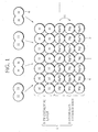
- FIG. 1 is a schematic diagram showing a hydrogen storage alloy according to the present invention.
- a hydrogen storage alloy 1 comprises a hydrogen storage base 2 and a catalytic layer 3.
- the hydrogen storage base 2 is a thin film of a mixture of a metal Mg 4 and an alloy (in the illustrated example, Mg 2 Ni 5).
- the ratio between Mg 4 and Mg 2 Ni 5 in the mixture is 0 to 10 (exclusive of 0) mol of Mg for 1 mol of Mg 2 Ni, more desirably 4 to 8 mol of Mg for 1 mol of Mg 2 Ni. It is particularly desirable that the mixture have composition represented by chemical formula Mg 6 Ni. Mg 4 and Mg 2 Ni 5 mixed this way experience chemical reactions shown below.
- hydrogen atoms H are passed on to Mg (or Mg 2 Ni) in an inner region.
- Mg or Mg 2 Ni
- the hydrogen storage base 2 be amorphous.
- the hydrogen storage base 2 being in the form of a thin film also contributes to quick absorption of hydrogen.
- the catalytic layer 3 is formed of Pd (palladium).
- the catalytic layer 3 is formed to cover the entire surface of the hydrogen storage base 2. Alternatively, the catalytic layer 3 may partly cover the surface of the hydrogen storage base 2.
- Pd catalyzes dissociation of molecular hydrogen into hydrogen atoms (H 2 ⁇ 2H). Hydrogen in the form of atoms is most quickly absorbed in Mg. Unlike Pt, Pd does not have the ability to catalyze ionization of hydrogen atoms. Thus, use of Pd as a catalyst allows hydrogen to stay in the form of atoms, which leads to quick absorption of hydrogen compared with when Pt is used as a catalyst.
- the catalytic layer 3 may be formed of a substance other than Pd (palladium), such as Pt (platinum), Nb (niobium) or ZrNi(zirconium nickel).
- FIG. 2 is a schematic diagram showing a hydrogen storage unit according to the present invention.
- the hydrogen storage unit 7 is in the form of an assembly of hydrogen storage fibers 8, namely nanofibers with a hydrogen storage alloy 1 (see FIG. 1 ) vapor-deposited thereon.
- a large number of hydrogen storage fibers 8 are tangled to intersect one another, thereby providing spaces 9 between one another.
- the individual nanofibers may be randomly oriented, but are tangled to provide spaces 9 having a size allowing hydrogen molecules to pass through.
- the hydrogen storage alloy 1 (see FIG. 1 ), vapor-deposited on such nanofibers, can provide a large surface area of the hydrogen storage base 2 (see FIG. 1 ), and thus, provide a large area of contact with hydrogen.
- the spaces 9 function as holes for hydrogen molecules to pass through, thereby allowing hydrogen to be absorbed not only in a surface region of the hydrogen storage unit 7 but also in an inner region of the hydrogen storage unit 7, thus enabling quick absorption of hydrogen.
- the hydrogen storage base 2 (see FIG. 1 ) can have a further increased surface area, and thus, a further increased area of contact with hydrogen, enabling quicker absorption of hydrogen.
- the hydrogen storage unit may be formed using other porous materials having holes allowing hydrogen to pass through.
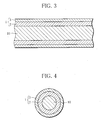
- FIG. 3 is a longitudinal cross-sectional view of a hydrogen storage fiber
- FIG. 4 a transverse cross-sectional view of the hydrogen storage fiber shown in FIG. 3 .
- a hydrogen storage fiber 8 comprises a nanofiber 10, a hydrogen storage base (hydrogen storage layer) 2 and a catalytic layer 3. More specifically, a layer of a hydrogen storage alloy 1 is vapor-deposited on the surface of the nanofiber 10. A large number of such hydrogen storage fibers 8 are tangled to intersect one another and form an assembly functioning as a hydrogen storage unit 7. When the nanofiber 10 has a smooth surface, the hydrogen storage alloy is uniformly vapor-deposited, as illustrated.
- the nanofibers can be produced by electrospinning or other processes.
- FIG. 5 is a longitudinal cross-sectional view of a hydrogen storage fiber of another type
- FIG. 6 a transverse cross-sectional view of the hydrogen storage fiber shown in FIG. 5 .
- a hydrogen storage alloy 1 is in the form of nanoparticles having a sphere-shaped hydrogen storage base of Mg and Mg 2 Ni (hydrogen storage core) 2 surround by a spherical catalyst layer 3 of Pd.
- the hydrogen storage cores 2 and the catalyst layer 3 form a colloid.
- the hydrogen storage fiber 8 is a nanofiber 10 with such nanoparticles of the hydrogen storage alloy adhering to its circumference.
- the hydrogen storage alloy 1 can be obtained in various forms by using appropriately-selected alloy 1-making processes.
- FIG. 7 is a graph showing how pressure varies with time when hydrogen is absorbed with a hydrogen storage unit according to the present invention.
- this test was conducted using an apparatus comprising a four-way tube containing a hydrogen storage unit, with its three ports, each fitted with a valve, being connected to a pressure gauge, a vacuum pump and a hydrogen canister, respectively.
- the four-way tube was depressurized with the vacuum pump until the pressure therein was stabilized (approximately 20Pa).
- the valve connected to the vacuum pump was closed and the valve connected to the hydrogen canister was opened.
- hydrogen was supplied so that the pressure in the four-way tube reached a desired value
- the valve connected to the hydrogen canister was closed and variation in pressure was monitored with the pressure gauge.
- the pressure dropped from 107190Pa to 320Pa.
- the hydrogen storage alloy used was Mg 2 Ni+Pd and the hydrogen supplied was 100%H 2 , which was supplied at the rate of 6 (ml/min).
Landscapes
- Chemical & Material Sciences (AREA)
- Engineering & Computer Science (AREA)
- Organic Chemistry (AREA)
- Chemical Kinetics & Catalysis (AREA)
- Mechanical Engineering (AREA)
- Inorganic Chemistry (AREA)
- Materials Engineering (AREA)
- Combustion & Propulsion (AREA)
- Life Sciences & Earth Sciences (AREA)
- Manufacturing & Machinery (AREA)
- Metallurgy (AREA)
- Sustainable Energy (AREA)
- Sustainable Development (AREA)
- Environmental & Geological Engineering (AREA)
- Composite Materials (AREA)
- Crystallography & Structural Chemistry (AREA)
- General Chemical & Material Sciences (AREA)
- Electrochemistry (AREA)
- General Life Sciences & Earth Sciences (AREA)
- Geology (AREA)
- Power Engineering (AREA)
- Transportation (AREA)
- Hydrogen, Water And Hydrids (AREA)
- Catalysts (AREA)
- Powder Metallurgy (AREA)
Applications Claiming Priority (1)
| Application Number | Priority Date | Filing Date | Title |
|---|---|---|---|
| PCT/JP2009/065504 WO2011027461A1 (ja) | 2009-09-04 | 2009-09-04 | 水素吸蔵合金及びこれを用いた水素吸蔵ユニット |
Publications (2)
| Publication Number | Publication Date |
|---|---|
| EP2474376A1 true EP2474376A1 (de) | 2012-07-11 |
| EP2474376A4 EP2474376A4 (de) | 2013-08-14 |
Family
ID=43649023
Family Applications (1)
| Application Number | Title | Priority Date | Filing Date |
|---|---|---|---|
| EP20090848992 Withdrawn EP2474376A4 (de) | 2009-09-04 | 2009-09-04 | Wasserstoffspeicherlegierung und wasserstoffspeichereinheit damit |
Country Status (7)
| Country | Link |
|---|---|
| US (1) | US8481151B2 (de) |
| EP (1) | EP2474376A4 (de) |
| JP (1) | JPWO2011027461A1 (de) |
| KR (1) | KR101604512B1 (de) |
| CN (1) | CN102596451B (de) |
| CA (1) | CA2771360A1 (de) |
| WO (1) | WO2011027461A1 (de) |
Families Citing this family (8)
| Publication number | Priority date | Publication date | Assignee | Title |
|---|---|---|---|---|
| US9045335B2 (en) * | 2010-08-18 | 2015-06-02 | The Governors Of The University Of Alberta | Kinetic stabilization of magnesium hydride |
| CN103972568A (zh) * | 2014-04-03 | 2014-08-06 | 上海华篷防爆科技有限公司 | 一种铁基合金储氢装置 |
| CN103968239A (zh) * | 2014-04-03 | 2014-08-06 | 上海华篷防爆科技有限公司 | 一种铜基合金储氢装置 |
| CN103968243A (zh) * | 2014-04-03 | 2014-08-06 | 上海华篷防爆科技有限公司 | 一种由铁基多孔金属复合材料制备的储氢装置 |
| CN103968238A (zh) * | 2014-04-03 | 2014-08-06 | 上海华篷防爆科技有限公司 | 一种铁基合金复合材料的储氢装置 |
| CN103968244B (zh) * | 2014-04-03 | 2016-09-14 | 上海华篷防爆科技有限公司 | 一种银氧化镉复合材料制备的储氢装置 |
| US9533884B1 (en) | 2016-05-24 | 2017-01-03 | Kuwait Institute For Scientific Research | Composition for hydrogen storage |
| CN114411028B (zh) * | 2022-01-21 | 2022-09-20 | 徐州工程学院 | 一种微量镍复合层状镁复合材料及其制备方法和应用 |
Family Cites Families (11)
| Publication number | Priority date | Publication date | Assignee | Title |
|---|---|---|---|---|
| JPH0784636B2 (ja) * | 1986-09-12 | 1995-09-13 | マツダ株式会社 | 水素吸蔵合金 |
| JPS63177397A (ja) | 1987-01-19 | 1988-07-21 | Mitsubishi Electric Corp | 半導体集積回路装置 |
| JPS63177397U (de) * | 1987-05-08 | 1988-11-17 | ||
| EP0815273B1 (de) * | 1995-02-02 | 2001-05-23 | Hydro-Quebec | Nanokristallines material auf mg-basis und dessen verwendung zum transport und zum speichern von wasserstoff |
| JP4456712B2 (ja) * | 2000-02-04 | 2010-04-28 | 株式会社アルバック | 水素ガス貯蔵材料及び貯蔵方法 |
| JP2003147473A (ja) | 2001-11-14 | 2003-05-21 | Matsushita Electric Ind Co Ltd | 水素貯蔵材料およびその製造法ならびに水素発生装置 |
| JP2004256860A (ja) * | 2003-02-25 | 2004-09-16 | Tdk Corp | 水素吸蔵体 |
| JP2004261675A (ja) * | 2003-02-28 | 2004-09-24 | Furukawa Electric Co Ltd:The | ガス貯蔵材料 |
| US7211541B2 (en) * | 2003-12-11 | 2007-05-01 | Ovonic Hydrogen Systems Llc | Mg—Ni hydrogen storage composite having high storage capacity and excellent room temperature kinetics |
| JP4735485B2 (ja) * | 2006-09-07 | 2011-07-27 | トヨタ自動車株式会社 | 水素吸着材料の製造方法 |
| KR101022857B1 (ko) * | 2008-01-16 | 2011-03-17 | 인하대학교 산학협력단 | 수소저장용 전이금속 도금된 다공성 탄소나노섬유 복합체의제조방법 |
-
2009
- 2009-09-04 CN CN200980162282.2A patent/CN102596451B/zh active Active
- 2009-09-04 KR KR1020127004565A patent/KR101604512B1/ko active Active
- 2009-09-04 CA CA 2771360 patent/CA2771360A1/en not_active Abandoned
- 2009-09-04 JP JP2011529751A patent/JPWO2011027461A1/ja active Pending
- 2009-09-04 WO PCT/JP2009/065504 patent/WO2011027461A1/ja not_active Ceased
- 2009-09-04 EP EP20090848992 patent/EP2474376A4/de not_active Withdrawn
- 2009-09-04 US US13/393,798 patent/US8481151B2/en active Active
Also Published As
| Publication number | Publication date |
|---|---|
| KR20120076423A (ko) | 2012-07-09 |
| CA2771360A1 (en) | 2011-03-10 |
| EP2474376A4 (de) | 2013-08-14 |
| WO2011027461A1 (ja) | 2011-03-10 |
| KR101604512B1 (ko) | 2016-03-17 |
| US20120164432A1 (en) | 2012-06-28 |
| US8481151B2 (en) | 2013-07-09 |
| CN102596451A (zh) | 2012-07-18 |
| CN102596451B (zh) | 2015-01-07 |
| JPWO2011027461A1 (ja) | 2013-01-31 |
Similar Documents
| Publication | Publication Date | Title |
|---|---|---|
| US8481151B2 (en) | Hydrogen storage alloy and hydrogen storage unit using same | |
| US8871671B2 (en) | Hydrogen storage unit | |
| Chen et al. | Synergy between metallic components of MoNi alloy for catalyzing highly efficient hydrogen storage of MgH2 | |
| Modi et al. | Room temperature metal hydrides for stationary and heat storage applications: a review | |
| US8172928B2 (en) | Fuel source for electrochemical cell | |
| Kobayashi et al. | Double enhancement of hydrogen storage capacity of Pd nanoparticles by 20 at% replacement with Ir; systematic control of hydrogen storage in Pd–M nanoparticles (M= Ir, Pt, Au) | |
| Wang et al. | Effect of catalytic Pd coating on the hydrogen storage performances of ZrCo alloy by electroless plating method | |
| EP2164626A1 (de) | Wasserstoffspeicherung in nanoporösen anorganischen netzwerken | |
| US7985704B2 (en) | Method of regenerating absorbent | |
| Yamaura et al. | Effect of surface coating element on hydrogen permeability of melt-spun Ni40Nb20Ta5Zr30Co5 amorphous alloy | |
| JP4347129B2 (ja) | 水素製造用反応筒及び反応板 | |
| JP5898037B2 (ja) | 保持部材及び水素製造装置 | |
| JP2011143335A (ja) | 水素分離装置及び水素分離装置の製造方法 | |
| US7736609B1 (en) | Hydrogen purification system | |
| EP4476165B1 (de) | Vorrichtung zur speicherung von wasserstoff in fester form | |
| CN201140984Y (zh) | 多元材料储氢装置 | |
| Balcerzak et al. | An insight into separating H 2 from natural gas/H 2 mixtures using Mg-based systems | |
| JP2004011003A (ja) | 水素貯蔵材料およびそれを用いた水素貯蔵容器 | |
| CN223582996U (zh) | 具有缓冲功能的供氢系统以及用氢设备 | |
| Oztek | Recovery of hydrogen and helium from their mixtures using metal hydrides | |
| Shih et al. | Hydrogen gas-rechargeable metal hydride electrode for Ni-MH battery | |
| Shan et al. | A micro-fabricated hydrogen storage module with sub-atmospheric activation and durability in air exposure | |
| CN119481175A (zh) | 具有缓冲功能的供氢系统以及用氢设备 | |
| Yang | The Art of Nanoconfinement of Borohydride & Designing of Catalysts for Catalytic Hydrogen Combustion | |
| Nowak et al. | Solid-State Hydrides |
Legal Events
| Date | Code | Title | Description |
|---|---|---|---|
| PUAI | Public reference made under article 153(3) epc to a published international application that has entered the european phase |
Free format text: ORIGINAL CODE: 0009012 |
|
| 17P | Request for examination filed |
Effective date: 20120228 |
|
| AK | Designated contracting states |
Kind code of ref document: A1 Designated state(s): AT BE BG CH CY CZ DE DK EE ES FI FR GB GR HR HU IE IS IT LI LT LU LV MC MK MT NL NO PL PT RO SE SI SK SM TR |
|
| DAX | Request for extension of the european patent (deleted) | ||
| A4 | Supplementary search report drawn up and despatched |
Effective date: 20130711 |
|
| RIC1 | Information provided on ipc code assigned before grant |
Ipc: B22F 1/02 20060101AFI20130705BHEP Ipc: C22C 49/04 20060101ALI20130705BHEP Ipc: C22C 47/06 20060101ALI20130705BHEP |
|
| 17Q | First examination report despatched |
Effective date: 20141124 |
|
| STAA | Information on the status of an ep patent application or granted ep patent |
Free format text: STATUS: THE APPLICATION IS DEEMED TO BE WITHDRAWN |
|
| 18D | Application deemed to be withdrawn |
Effective date: 20151118 |