EP2474425A1 - Applikator mit ventil - Google Patents
Applikator mit ventil Download PDFInfo
- Publication number
- EP2474425A1 EP2474425A1 EP10813737A EP10813737A EP2474425A1 EP 2474425 A1 EP2474425 A1 EP 2474425A1 EP 10813737 A EP10813737 A EP 10813737A EP 10813737 A EP10813737 A EP 10813737A EP 2474425 A1 EP2474425 A1 EP 2474425A1
- Authority
- EP
- European Patent Office
- Prior art keywords
- agitator
- view
- applicator
- ink
- barrel
- Prior art date
- Legal status (The legal status is an assumption and is not a legal conclusion. Google has not performed a legal analysis and makes no representation as to the accuracy of the status listed.)
- Withdrawn
Links
Images


Classifications
-
- B—PERFORMING OPERATIONS; TRANSPORTING
- B43—WRITING OR DRAWING IMPLEMENTS; BUREAU ACCESSORIES
- B43K—IMPLEMENTS FOR WRITING OR DRAWING
- B43K8/00—Pens with writing-points other than nibs or balls
- B43K8/003—Pen barrels
-
- B—PERFORMING OPERATIONS; TRANSPORTING
- B43—WRITING OR DRAWING IMPLEMENTS; BUREAU ACCESSORIES
- B43K—IMPLEMENTS FOR WRITING OR DRAWING
- B43K23/00—Holders or connectors for writing implements; Means for protecting the writing-points
- B43K23/08—Protecting means, e.g. caps
- B43K23/12—Protecting means, e.g. caps for pens
- B43K23/126—Protecting means, e.g. caps for pens with clips
-
- B—PERFORMING OPERATIONS; TRANSPORTING
- B43—WRITING OR DRAWING IMPLEMENTS; BUREAU ACCESSORIES
- B43K—IMPLEMENTS FOR WRITING OR DRAWING
- B43K25/00—Attaching writing implements to wearing apparel or objects involving constructional changes of the implements
- B43K25/02—Clips
- B43K25/022—Clips attached to a pen cap
-
- B—PERFORMING OPERATIONS; TRANSPORTING
- B43—WRITING OR DRAWING IMPLEMENTS; BUREAU ACCESSORIES
- B43K—IMPLEMENTS FOR WRITING OR DRAWING
- B43K8/00—Pens with writing-points other than nibs or balls
- B43K8/02—Pens with writing-points other than nibs or balls with writing-points comprising fibres, felt, or similar porous or capillary material
- B43K8/04—Arrangements for feeding ink to writing-points
Definitions
- the present invention relates to a valved applicator which opens the valve opposing the elastic force of a spring part by pressing an applying part as a writing tip to thereby feed ink to the applying part.
- Marker pens that mark down on a metal material or resin material with an oil-based ink or the like, are frequently used when marking products in a factory, and in most cases those pens are stored with their writing point downward.
- valve interior cannot be agitated so that the concealing material or pigment in the ink precipitates, whereby the interior of the valve is clogged, and the value will not provide correct functions, possibly causing writing failure.
- valved applicator of this patent document 1 the agitator will not go into the interior of the valve at the time of agitation, so that the valve interior cannot be well agitated.
- the present invention is to provide a valved applicator in which an agitator can go into the valve interior at time of agitation.
- the present invention relates to a valved applicator.
- the present invention is a valved applicator in which an ink tank for storing ink in the rear part of a barrel cylinder is communicated with the interior of the front part of the barrel cylinder and an agitator is arranged inside the ink tank while an applying part with its front end projected out, a valve element that opens and closes an ink flow path and a spring part that urges the valve element forwards by elastic force are arranged in the front part of the barrel cylinder, and when the applying part at the writing point is pressed, the valve element is opened opposing the elastic force of the spring part to thereby feed ink to the applying part, characterized in that a space which the agitator can be inserted into and pulled out of is provided inside the spring part.
- the agitator is given in a rod-like form having a large diametric portion greater in diameter than the other part while a constraint receiver that engages the large-diametric portion of the agitator so as to restrain the front end of the agitator from abutting the interior of the front end of the spring part is provided in the barrel cylinder.
- the spring part is formed of resin, having the valve element integrated in the front end thereof.
- the spring part is formed of resin, having an integrally formed constraint receiver as an abutment smaller in inside diameter than the outside diameter of the large-diametric portion of the agitator, in the rear end thereof.
- the agitator is formed of resin and has a symmetrical shape with respect to the front-to-rear direction.
- the agitator is given in a rod-like form having a rear end part that is enlarged in diameter than the other part while a space which the agitator can be inserted into and pulled out of is provided inside the spring part.
- the agitator goes into the interior of the spring part when the applicator is shaken to agitate by the agitator, so that there is no risk of writing failure, which would occur due to malfunction of the valve as a result of valve clogging when concealing material or pigment in the ink has precipitated.
- the agitator when the agitator is given in a rod-like form having a large diametric portion greater in diameter than the other part while a constraint receiver that engages the large-diametric portion of the agitator so as to restrain the front end of the agitator from abutting the interior of the front end of the spring part is provided in the barrel cylinder, the agitator will not directly collide with the valve element, so that there is no risk of the valve opening during agitation and hence there is no risk of ink leaking or flooding.
- the spring part is formed of resin
- the valve element integrated in the front end thereof
- the spring part is formed of resin, with an integrally formed constraint receiver as an abutment smaller in inside diameter than the outside diameter of the large-diametric portion of the agitator, in the rear end thereof, there is no need to perform separate attachment so that molding and handling can be further simplified.
- the agitator is made of resin and can be formed by injection molding, this produces excellent effect such as producing good productivity.
- FIGS. 1 to 20 are illustrative diagrams showing applicators (e.g., writing instruments) provided with a cap and their component structures according to the embodiments.
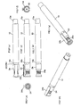
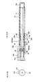
- FIGS. 1(a) to (g) are overall illustrative diagrams of an applicator according to an embodiment.
- FIGS. 2(a) and (b) are illustrative diagrams of the configuration of an applicator according to the first embodiment;
- FIGS. 3(a) to (e) are illustrative diagram of a configuration of the applicator in which a spring part integrally formed with a valve element is assembled with a sponge and attached with an agitator.
- FIGS. 1(a) to (g) are overall illustrative diagrams of an applicator according to an embodiment.
- FIGS. 2(a) and (b) are illustrative diagrams of the configuration of an applicator according to the first embodiment;
- FIGS. 3(a) to (e) are illustrative diagram of
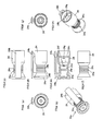
- FIGS. 4(a) to (h) are structural illustrative diagrams of a cap of the applicator;
- FIGS. 5(a) to (f) are illustrative diagrams of examples 1 and 2 of caps; and
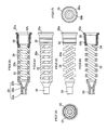
- FIGS. 6(a) to (f) are illustrative diagrams of the spring part integrally formed with a valve element.
- FIG. 7 is an overall illustrative diagram in vertical section of an applicator of the second embodiment.
- FIGS. 8 to 11 are illustrative diagrams of an applicator and its agitator of the third embodiment;
- FIGS. 12 to 14 are illustrative diagrams of an applicator and its agitator of the fourth embodiment;
- FIGS. 15 to 18 are illustrative diagrams of an applicator and its agitator of the fifth embodiment; and
- FIGS. 19 to 20 are illustrative diagrams of an applicator and its agitator of the sixth embodiment.
- a valved applicator is configured such that an ink tank 12 that is located in the rear part of a barrel cylinder 10 for storing ink is communicated with the interior of the front part of barrel cylinder 10, an agitator 14 is arranged inside the ink tank 12 while an applying part 16 with its front end projected out, a valve element 20 that opens and closes an ink flow path 18 and a spring part 22 that elastically urges the valve element 20 forwards are arranged in the front part of the barrel cylinder 10, and when applying part 16 at the writing point is pressed, the valve element 20 is opened opposing the elastic force of spring part 22 to thereby feed ink to the applying part 16 and enable the applicator to apply ink (write) onto a target object.
- valved applicator The specific configuration of the valved applicator will be explained.
- the rear part of barrel cylinder 10 that is closed at the rear end thereof forms ink tank 12 for storing ink in its interior space while the rear end 10a is reduced stepwise in outside diameter so that a cap 24 can be fitted thereon.
- the rear end (fit-in front) 26a of front barrel 26 reaches around the middle part of barrel cylinder 10 while a plurality of ribs 12a are projectively formed in the axial direction from the rear end to near the middle part on the interior surface of ink tank 12 of barrel cylinder 10.
- the aforementioned front barrel 26 has a flange 26b on the outer periphery in the middle part. This flange 26b abuts the front end 10b of barrel cylinder 10 to position the front barrel so that it will not plunge farther into barrel cylinder 10. Further, an annular valve seat 26c is projectively and inwardly formed on the inner periphery of front barrel 26 so that the outer periphery of valve element 20 will come into and out of contact with this valve seat 26c. Formed on the outer peripheral part behind flange 26b of front barrel 26 is a male thread 26d. This male thread 26d is mated with and fixed to a corresponding female thread 10c on the inner peripheral part of barrel cylinder 10 so that front barrel 26 will not slip out of barrel cylinder 10.
- a pair of flat cutouts are formed 180° apart from each other on the outer peripheral side of flange 26b so that a tool such as a wrench or the like can fit thereon.
- a rear part 28a of a plastic mouthpiece 28 as a holder that encloses applying part 16 so that applying part 16 can move back and forth.
- the front part 28b of this plastic mouthpiece 28 is formed on its inner peripheral surface with ribs 28c that guides applying part 16 moving back and forth.
- the front part 28b of plasticmouthpiece 28 is formed to be smaller in diameter than rear part 28a, correspondingly to applying part 26 while the middle part of the plastic mouthpiece is made greater like a flange in outside diameter so as to abut the front end of front barrel 26 so that rear part 28a will not plunge farther into front barrel 26.
- a sponge 30 is arranged inside rear part 28a of plastic mouthpiece 28, enclosing the outer periphery of the rear part of the applying part 16 and valve element 20.
- sponge 30 is located in front of valve seat 26c of front barrel 26 temporarily stores ink and provides an adjusting function of stably flowing ink to applying part 16, in order to prevent ink from flushing from the ink path toward applying part 16 and flowing out through a gap (between ribs 28c of plastic mouthpiece' s front part 28b and the like) when the contact between valve element 20 and valve seat 26c is opened.
- Applying part 16 is an approximately rod-like configuration as a whole, tapering with its tip rounded and its rear end cut off.
- the aforementioned spring part 22 is formed, as shown in FIGS. 2 , 3 and 6 , of valve element 20 at the front thereof, an approximately helical elastic portion 22a in the middle thereof and a cylindrical part (constraint receiver) 32 having a flange-like portion 32a in the rear thereof.
- Valve element 20 is formed of a cylindrical front part 20a, a rear part 20b having a conical side and a partitioning wall 20c in the middle.
- a space 34 which the agitator 14 can be inserted into and taken out of. That is, that spring part defines hollow space 34 that extends from cylindrical part 32 at the rear through elastic portion 22a to the rear part 20b of valve element 20 at the front, in the center in section, so that agitator 14 can be inserted into and pulled out of this space 34.
- the aforementioned agitator 14 is given in a rod-like form with its rear end part 14a made greater in diameter than the other part and formed in a flange shape with a partial cutout.
- Spring part 22 has cylindrical part (constraint receiver) 32 as its rear end part that is integrally formed of resin, the cylindrical part having an inner step 32b forming an abutment having an inside diameter that is smaller than the outside diameter of the rear end part 14a of the agitator 14.
- This cylindrical part 32 engages the rear end part 14a of the agitator 14 with its inner step 32b so as to restrain the front end of the agitator 14 from abutting the inner surface (partition 20c) of valve element 20 at the front end of spring part 22.
- Cylindrical part 32 at the rear end of the spring element 22 has projected and indented outer peripheral surface, which engages the projected and indented inner peripheral surface in the rear end of front barrel 26 so that spring part 22 will not come off from front barrel 26.
- the rear end of cylindrical part 32 extends outwards in diameter, forming flange portion 32a so that rear end 26a of front barrel 26 abuts flange-like portion 32a when front barrel 26 is attached, so as to prevent spring element from plunging down further. Further, when front barrel 26 with this spring part 22 having been fitted therein is inserted and screw-fixed to front end 10b in barrel cylinder 10, the flange-like portion 32a is positioned by ribs 12a on the inner peripheral surface of ink tank 12.
- this flange-like portion 32a is held between front barrel 26 on the front side and ribs 12a on the rear side so that rear end part is fixed in position inside barrel cylinder 10 while valve element 20 arranged at the front end can move forwards and backwards.
- Elastic portion 22a of the spring part 22 is formed by shaping two lines in an approximately helical configuration, along four surfaces each having an approximately rectangular shape when viewed in cross section, as shown in FIG. 3 .
- the lines on one pair of two opposing surfaces are arranged approximately perpendicular to the axial direction while the lines are arranged obliquely with respect to the axial direction, on the other pair of two opposing surfaces.
- Spring part 22 has the aforementioned valve element 20 as its front end that is integrally formed of resin.
- cap 24 will be explained.
- Cap 24 is externally fixed on front barrel 26 in a detachable manner so as to cover from front barrel 26, holder 28 and applying part 16 in the front part of the applicator.
- Cap 24 has a holding portion 24a that is narrowed in the center with respect to the axial direction, having an outside diameter reduced compared to that of the front part and that of the rear part in the axial direction so as to allow the fingers to pick it up.
- annular holding portion 24a is formed so that the user is ready to take out from barrel cylinder 10 by holding it with the fingertips. Further, sinceprovision of holding portion 24a makes it possible to positively apply a holding force on the cap by picking narrowed holding portion 24a when the user of the applicator tries to take out cap 24 in their gloved fingers, cap 24 can be put on and taken off without slipping, hence making it possible to readily use especially on a worksite and/or construction site.
- narrowed holding portion 24a is more readily to hold compare to the simple jaggedness in the prior art, hence the cap will not be slipped off. Further narrowed holding portion 24a may be bound with a cord so as to make it easy to carry.
- cap 24 is narrowed around holding portion 24a, the portion that seals the outer periphery of holder 28 and the like supporting applying part 16 in the front end of barrel cylinder 10 can also be narrowed so that thinning of cap 24 can be easily realized.
- Cap 24 has an approximately bowl-like configuration, closed at the front end and annularly indented in the middle thereof in the axial direction and having a rear end that abuts flange 26b of front barrel 26.
- a clip 24b is provided on the outer side of cap 24 so that the applicator can be fixed by clip 24b nipping a user's pocket.
- a slip stopper 24c is formed on the outer side of cap 24.
- the aforementioned slip stopper 24c is formed of multiple flange-like projections and indentations arranged in parallel in the circumferential direction around the bottom of holding portion 24a.
- the tips of the projections in the jagged configuration of slip stopper 24c are formed with acute angles (equal to or less than 90°) having a rectangular configuration when viewed in section. Formation of the tips of the projections with acute angles enables even gloved fingertips to easily hold, hence making it possible to take off the cap easily with weak force.
- the acute angles may be given in various forms such as a triangular configuration, serrated configuration and the like when the projections of the jagged configuration are viewed in section. In example 1, as shown in FIGS.
- the jagged configuration of slip stopper 24c on the outer peripheral side in the bottom of holding portion 24a is formed with annular ribs having a cross-section of an acute-angled triangle (equal to or less than 90°) with its distal end pointed radially outwards.
- the jagged configuration of slip stopper 24c on the outer peripheral side in the bottom of holding portion 24a is formed with annular ribs having a cross-section of an acute-angled triangle (equal to or less than 45°) with its distal end pointed radially outwards and rearwards.
- the slip stopper has a configuration of umbrellas opening rearwards.
- the surface of barrel cylinder 10 is also formed with slip stopper shaping such as a jagged configuration or the like.
- the shaping for slip stopper may be formed by provision of an elastic material such as rubber etc., other than the above-described jagged configuration.
- Clip 24b arranged over the outer peripheral side of cap 24 is formed to be narrower than the outside diameter of the holding portion 24a. Provision of clip 24b having a smaller width than the outside diameter of the holding portion 24a permits the user to hold holding portion 24a without any interference while providing the essential function of clip 24b.
- the thickness of cap 24 is preferably specified such that cap top diameter > holding portion 24a > clip 24b width.
- holder 28 for holding the applying part is arranged in the front end of the barrel cylinder and formed so that the front side of holder 28 is smaller in diameter than the rear side.
- cap 24 can be fitted to front barrel 26 (the first fitting structure) or cap 24 may be fitted to both front barrel 26 and holder 28 (the second fitting structure) (in FIG. 4(h) fitting ribs 24h on the inner peripheral side of cap 24 are shown).
- the inner peripheral surface of cap 24 is made to fit on the outer peripheral surface of the front part of flange 26b of front barrel 26.
- Fitting ribs 26h and 24h are annularly formed correspondingly on the outer peripheral surface of front barrel 26 and the inner peripheral surface of cap 24, respectively, so that ribs 26h and 24h mate each other, providing anti-falling and sealing functions, as cap 24 is fitted.
- sealing structures 24d and 28d for keeping the surrounding space of the applying part airtight are formed at associated positions on the outer periphery of the small-diametric part of holder 28 and the inner periphery of cap 24.
- sealing structure 24d of the inner periphery of cap 24 is formed on the inner side of the holding portion 24a. In this way, sealing structures 24d and 28d are formed in the small-diametric fitting positions, hence it is possible to enhance sealing performance by shortening the sealing length, compared to the large-diametric case.
- plural projections designated by a reference numeral 24f are projections on the inner periphery of cap 24, providing functions of supporting the outer periphery of the small-diametric holder 28 to keep it center and reliably fitting sealing structures 24d and 28d to each other to keep airtightness.
- a reference numeral 24g designates fitting ribs that extend in the axial direction on the inner peripheral and enable the cap 24 fitted to the small-diametric part of rear end 10a of barrel cylinder 10 even when cap 24 is unused.
- the inner periphery of the holding portion 24a and its front side of cap 24 is so formed that the inside diameter is smaller around applying part 16 than around holder 28 with its front end closed while an outer peripheral part 24e in front of the holding portion 24a is made greater toward the front, forming a hollowed bowl-like shape.
- the outer peripheral part 24e in front of holding portion 24, given in the bowl-like shape on the outer side is formed to be thin so that cap 24 will not produce sinks at the time of resin molding.
- this outer peripheral part 24e is integrally formed in junction with cap 24.
- each component of the applicator according to the present invention is preferably formed of resin materials.
- applying part 16 is formed of a bundle of fibers, continuous-foamed body, molding or the like of polyethylene terephthalate (PET).
- PET polyethylene terephthalate
- the barrel cylinder 10, front barrel 26, holder 28 and cap 24 are formed of polypropylene (PP).
- Spring part 22 and agitator 14 are formed of polyacetal (POM) while sponge 30 is formed of urethane.
- each part is formed by injection molding. Since barrel cylinder 10 and front barrel 26 are formed with high precision by injection molding, the opposing screw-joint parts can be made with high precision while rear end 10a is formed with little burrs so that the external appearance can be improved.
- the applying part 16 is placed downwards or the like while valve element 20 at the front end of spring part 22 is pressed forwards by the elastic force of elastic portion 22a and put into hermetic contact with valve seat 26c of front barrel 26 so that ink flow path 18 is closed (in the state shown in FIG. 2 ).
- ink is agitated at the time of using.
- agitator 14 moves back and forth inside ink tank 12 to thereby agitate ink.
- the agitator 14 has flange-like rear end part 14a that is enlarged in diameter, the flange is caught by inner step 32b of cylindrical part 32 at the rear end of front barrel 26 as shown in FIG. 2 , so that the agitator will not move farther towards valve element 20. Accordingly, there is no risk of valve element 20 being opened by any impact.
- agitator 14 is given in a rod-like form having a greater diameter in the rear end part than the other part, and space 34 which the agitator 14 can be inserted into and pulled out from is formed inside the spring part 22 while in barrel cylinder 10, a constraint receiver to restrain the front end of the agitator 14 from abutting the interior in the front end portion of spring part 22 by making inner step 32b of cylindrical part 32 catch the rear end part of the agitator 14 is provided.
- valve element 20 that is integrally formed of resin is formed at the front end of spring part 22, it is possible to reduce the number of parts and simplify molding and handling.
- cylindrical part (constraint receiver) having inner step 32b as an abutment having an inside diameter smaller than the outside diameter at the rear end part of the agitator 14 is formed of resin integrally with spring part 22 at its rear end part, there is no need of separate attachment, and hence molding and handling can be further simplified.
- agitator 14 is made of resin and can be formed by injection molding, this produces good productivity and other effects.
- valved applicator of the present invention is not limited to the first embodiment, and various kinds of variations can be realized.
- the valved applicator of the present invention may be formed as in the second embodiment shown in FIG. 7 .
- the same reference numerals are allotted to the same components as those in the applicator of the first embodiment.
- plastic mouth piece 28 is fitted at the front end of front barrel 26 and valve seat 26c is integrally formed with the front barrel, a plastic mouthpiece is integrally formed with the front end part of front barrel 26 while the valve seat is configured so that a valve receiving part 36 is separated from the front barrel so that the valve seat is fitted into the front barrel 26.
- This valve receiving part 36 is formed of an approximately annular outer peripheral body 36a and an abutment 36b that projects inwards like a flange from the inner peripheral surface. Rear part 20b of valve element 20 comes into oblique contact with and out of the abutment so as to open and close the valve.
- valved applicator according to the second embodiment is constructed so that front barrel 26 and valve receiving part 36 are formed separately, the material of valve receiving part 36 can be selected freely, hence this configuration is advantageous in obtaining the hermitic performance for the valve.
- valved applicator of the present invention can be configured without ribs inside the ink tank and without a clip for the cap.
- agitators 14 which are symmetrical (symmetrical between front and rear halves) with respect to the front-to-rear direction (longitudinal direction) will be described.
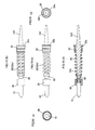
- FIGS. 8(a) to (b) are overall illustrative diagrams of an applicator according to the third embodiment
- FIGS. 9(a) to (e) are illustrative diagrams of the applicator, in which a spring part with a valve element integrally formed at the front end thereof is assembled with an applying part and a sponge part and is attached with an agitator
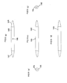
- FIGS. 10(a) to (e) are illustrative diagrams of an agitator arranged inside the applicator
- FIG. 11 is a perspective view of an agitator arranged inside the applicator.
- the applicator according to the third embodiment has the same configuration as the applicator according to the second embodiment shown in FIG. 7 , except in that the configuration of an agitator 14X is significantly different, ribs are formed inside ink tank 12 and clip 24b is provided for cap 24. The same components are allotted with the same reference numerals.
- agitator 14X provided for the applicator according to the third embodiment is given in an approximately rod-like form with a front end part (14F) and rear end part (14R) in the front-to-rear direction, tapered in the same manner, forming tapering ends.
- the agitator 14X is symmetrical with respect to the front-to-rear direction and has a single projection 14b projected radially outwards at the middle point in the front-to-rear direction.
- This agitator 14X may be handled without caring about the direction of insertion into the barrel cylinder, hence being excellent in assembly performance. Further, the front part of agitator 14X goes into space 34 that opens rearwards in spring part 22, in an insertable and removable manner, from the hollow of cylindrical part 32. In this condition, projection 14b abuts inner step 32b of cylindrical part 32 so that the agitator will not enter farther. Further, the inner periphery of flange-like portion 32a of cylindrical part 32 is cut so as to open wider towards the rear, so that agitator 14X is liable to enter cylindrical part 32. Moreover, agitator 14 is arranged so that the rear part is projected into ink tank 12 when the front part is inserted into space 34 of spring part 22.
- FIGS. 12(a) to (b) are illustrative diagrams of an applicator according to the fourth embodiment
- FIGS. 13(a) to (e) are illustrative diagrams of the applicator, in which a spring part with a valve element integrally formed at the front end thereof is assembled with an applying part, a sponge part and an agitator
- FIGS. 14(a) to (e) are illustrative diagrams of an agitator arranged inside the applicator. Since the configuration other than agitator 14 is the same as the applicator according to the third embodiment, the same components are allotted with the same reference numerals.
- the applicator according to the fourth embodiment is formed so that its agitator 14Y is formed with a pair of projections 14b and 14b, on the outer periphery thereof at the middle point in the front-to-rear direction, projected radially outwards, axially symmetrically.
- Agitator 14Y is given in an approximately rod-like form with a front end part (14F) and rear end part (14R) in the front-to-rear direction, tapered in the same manner, forming tapering ends.
- the agitator may be handled without caring about the direction of insertion into the barrel cylinder, hence being excellent in assembly performance.
- paired projections 14b and 14b are projectively formed axially symmetrically and radially outwards to opposite sides, the agitator can abut inner step 32b of the cylindrical part 32 in a well-balanced manner, so that agitator 14Y is unlikely to jolt (unlikely to shake left and right) inside space 34 of spring part 22, hence producing little rattle and vibration.
- FIGS. 15(a) to (b) are illustrative diagrams of an applicator according to the fifth embodiment
- FIGS. 16(a) to (e) are illustrative diagrams of the applicator, in which a spring part with a valve element integrally formed at the front end thereof is assembled with an applying part and a sponge part and is attached with an agitator
- FIG. 17 is an illustrative diagram of the agitator arranged inside the applicator
- FIG. 18 is a perspective view of an agitator arranged inside the applicator.
- the applicator according to the fifth embodiment is formed so that its agitator 14Z has the maximum outside diameter at the middle point in the front-to-rear direction and is tapered towards both the front and rear ends from that middle point.
- Agitator 14Z is formed so that the outside diameter at that middle point is greater than the inside diameter of inner step 32b of cylindrical part 32.
- the agitator may be handled without caring about the direction of insertion into the barrel cylinder, hence being excellent in assembly performance.
- agitator 14Z has the maximum outside diameter at the middle point and is tapered as described above, the agitator is stopped and will not enter space 34 of spring part 22 farther when the middle point of agitator 14Z abuts inner step 32b of cylindrical part 32. In this case, in the stopped position the rear end of agitator 14Z faces ink tank 12.
- agitator 14Z when agitator 14Z goes into the space 34, the agitator smoothly enters and smoothly stops. Moreover, since agitator 14Z is not formed with any projections, the agitator can be readily formed because it is not necessary to provide projections to mold agitator 14Z.
- FIGS. 19(a) to (b) are illustrative diagrams of an applicator of the sixth embodiment and FIG. 20 is a perspective diagram of an agitator 14 arranged inside the applicator.
- the applicator according to the sixth embodiment is constructed so that an agitator 14 is given in an approximately rod-like form with its front end part and rear end part in the front-to-rear direction, tapered in the same manner, forming tapering ends. Accordingly, also in this case, owing to the symmetrical configuration of agitator 14 with respect to the front-to-rear direction, the agitator may be handled without caring about the direction of insertion into the barrel cylinder, hence being excellent in assembly performance. Moreover, since agitator 14 is not formed with any projections, the agitator can be readily formed because it is not necessary to provide projections to the mold of agitator 14.
- valved applicator of the present invention can be applied to applicators for applying chemicals, cosmetics and other application fluids to a target object as well as to various kinds of writing implements for writing on a target object.
Landscapes
- Pens And Brushes (AREA)
- Coating Apparatus (AREA)
Applications Claiming Priority (3)
| Application Number | Priority Date | Filing Date | Title |
|---|---|---|---|
| JP2009201766 | 2009-09-01 | ||
| JP2010192409A JP5608015B2 (ja) | 2009-09-01 | 2010-08-30 | 弁付塗布具 |
| PCT/JP2010/064940 WO2011027788A1 (ja) | 2009-09-01 | 2010-09-01 | 弁付塗布具 |
Publications (2)
| Publication Number | Publication Date |
|---|---|
| EP2474425A1 true EP2474425A1 (de) | 2012-07-11 |
| EP2474425A4 EP2474425A4 (de) | 2013-11-20 |
Family
ID=43649323
Family Applications (1)
| Application Number | Title | Priority Date | Filing Date |
|---|---|---|---|
| EP10813737.3A Withdrawn EP2474425A4 (de) | 2009-09-01 | 2010-09-01 | Applikator mit ventil |
Country Status (6)
| Country | Link |
|---|---|
| US (1) | US8944716B2 (de) |
| EP (1) | EP2474425A4 (de) |
| JP (1) | JP5608015B2 (de) |
| CN (1) | CN102574416B (de) |
| MX (1) | MX2012002152A (de) |
| WO (1) | WO2011027788A1 (de) |
Cited By (1)
| Publication number | Priority date | Publication date | Assignee | Title |
|---|---|---|---|---|
| US20160257161A1 (en) * | 2014-10-07 | 2016-09-08 | Epoch Chemical Co., Ltd. | Ink reservoir member for writing instrument, and valve type writing instrument using the same |
Families Citing this family (8)
| Publication number | Priority date | Publication date | Assignee | Title |
|---|---|---|---|---|
| JP2013144366A (ja) * | 2012-01-13 | 2013-07-25 | Mitsubishi Pencil Co Ltd | 塗布具 |
| JP2015057320A (ja) * | 2013-08-14 | 2015-03-26 | 株式会社サクラクレパス | 塗布具 |
| KR101818340B1 (ko) * | 2016-05-16 | 2018-01-12 | 김동권 | 명판 채색용 노즐 및 이를 포함하는 명판 채색용 모듈 |
| US11472221B2 (en) | 2017-04-21 | 2022-10-18 | Mitsubishi Pencil Company, Limited | Writing implement |
| WO2020189584A1 (ja) * | 2019-03-15 | 2020-09-24 | 三菱鉛筆株式会社 | 塗布具 |
| CN111846596B (zh) * | 2020-08-05 | 2025-07-11 | 圣戈班汇杰(杭州)新材料有限公司 | 一种便利的液体底涂剂包装 |
| DE102022206668A1 (de) * | 2022-06-30 | 2024-01-04 | Siemens Healthcare Gmbh | Vorrichtung zum Markieren eines Eintrittspunktes auf der Haut eines Patienten für eine Magnetresonanz-überwachte Nadel-Biopsie |
| CN117844302A (zh) * | 2023-12-15 | 2024-04-09 | 肇庆斯塔文化用品有限公司 | 一种可清洗墨水及其固定液及包括其的马克笔 |
Family Cites Families (21)
| Publication number | Priority date | Publication date | Assignee | Title |
|---|---|---|---|---|
| US1379057A (en) * | 1918-11-06 | 1921-05-24 | Thomas C Spelling | Fountain-pen |
| US2947015A (en) * | 1958-10-16 | 1960-08-02 | Hugh M Burt | Liquid shoe polish dispenser |
| US3106742A (en) * | 1960-11-25 | 1963-10-15 | American Can Co | Dispenser and applicator |
| DE3441609A1 (de) * | 1984-11-14 | 1986-05-22 | Bramlage Gmbh, 2842 Lohne | Salbenapplikator |
| US4844250A (en) * | 1987-11-16 | 1989-07-04 | Wheeling Stamping Company | Tamper-evident container assembly |
| JPH0545422Y2 (de) | 1987-12-29 | 1993-11-19 | ||
| JP2500887Y2 (ja) * | 1989-07-14 | 1996-06-12 | 株式会社サクラクレパス | 塗布具 |
| JP2575720Y2 (ja) * | 1993-01-29 | 1998-07-02 | パイロットインキ株式会社 | 塗布具 |
| JPH09216489A (ja) * | 1996-02-14 | 1997-08-19 | Zebra Pen Corp | 筆記具 |
| JP3926008B2 (ja) * | 1997-11-10 | 2007-06-06 | 株式会社サクラクレパス | 塗布具 |
| CN2344176Y (zh) * | 1998-10-28 | 1999-10-20 | 台生企业股份有限公司 | 笔具 |
| US6247865B1 (en) | 2000-06-09 | 2001-06-19 | Robert G. Russell | Marker device with attached cap |
| CN2487559Y (zh) * | 2001-05-29 | 2002-04-24 | 东莞福新文教用品厂有限公司 | 笔套 |
| JP2002355602A (ja) * | 2001-05-31 | 2002-12-10 | Pentel Corp | 塗布具 |
| JP4298968B2 (ja) | 2002-06-19 | 2009-07-22 | 株式会社呉竹 | 筆記具 |
| JP2004174956A (ja) * | 2002-11-28 | 2004-06-24 | Pentel Corp | 塗布具 |
| US7137751B2 (en) * | 2003-03-14 | 2006-11-21 | Societe Bic S.A. | Writing instrument with cushioning element |
| US6932531B2 (en) * | 2003-04-28 | 2005-08-23 | Sanford L.P. | Writing assembly with eraser assembly |
| JP4585777B2 (ja) * | 2003-07-07 | 2010-11-24 | パイロットインキ株式会社 | 筆記具 |
| JP2006056051A (ja) * | 2004-08-18 | 2006-03-02 | Mitsubishi Pencil Co Ltd | 液体塗布具 |
| CN201240143Y (zh) * | 2008-07-28 | 2009-05-20 | 樊淑英 | 一种防倒流笔 |
-
2010
- 2010-08-30 JP JP2010192409A patent/JP5608015B2/ja active Active
- 2010-09-01 MX MX2012002152A patent/MX2012002152A/es active IP Right Grant
- 2010-09-01 US US13/390,640 patent/US8944716B2/en not_active Expired - Fee Related
- 2010-09-01 CN CN201080038971.5A patent/CN102574416B/zh not_active Expired - Fee Related
- 2010-09-01 EP EP10813737.3A patent/EP2474425A4/de not_active Withdrawn
- 2010-09-01 WO PCT/JP2010/064940 patent/WO2011027788A1/ja not_active Ceased
Cited By (2)
| Publication number | Priority date | Publication date | Assignee | Title |
|---|---|---|---|---|
| US20160257161A1 (en) * | 2014-10-07 | 2016-09-08 | Epoch Chemical Co., Ltd. | Ink reservoir member for writing instrument, and valve type writing instrument using the same |
| US9950555B2 (en) * | 2014-10-07 | 2018-04-24 | Epoch Chemical Co., Ltd. | Ink reservoir member for writing instrument, and valve type writing instrument using the same |
Also Published As
| Publication number | Publication date |
|---|---|
| CN102574416B (zh) | 2015-03-11 |
| JP5608015B2 (ja) | 2014-10-15 |
| US8944716B2 (en) | 2015-02-03 |
| WO2011027788A1 (ja) | 2011-03-10 |
| CN102574416A (zh) | 2012-07-11 |
| MX2012002152A (es) | 2012-06-01 |
| JP2011072988A (ja) | 2011-04-14 |
| EP2474425A4 (de) | 2013-11-20 |
| US20120141189A1 (en) | 2012-06-07 |
Similar Documents
| Publication | Publication Date | Title |
|---|---|---|
| US8944716B2 (en) | Valved applicator | |
| EP3050712B1 (de) | Schreibinstrument und tintenpatrone | |
| JP7108097B2 (ja) | マーキングペン | |
| JP2023040304A (ja) | 筆記具 | |
| WO2013183633A1 (ja) | 筆記具 | |
| CN100497001C (zh) | 书写用具 | |
| JP6467575B2 (ja) | 容器 | |
| US20220218090A1 (en) | Liquid cosmetic material container | |
| US20140241781A1 (en) | Liquid applicator | |
| JP7184955B2 (ja) | マーキングペン | |
| JP5464959B2 (ja) | 塗付具のキャップ及びキャップを設けた塗付具 | |
| CN112368156A (zh) | 书写工具 | |
| JP2005131943A (ja) | 顔料インキ用ペン先及び筆記具 | |
| JP6596509B2 (ja) | インキカートリッジ及び筆記具 | |
| JP7117861B2 (ja) | 補充式筆記具及びそれに用いるインキ吸蔵体 | |
| JP6300559B2 (ja) | ノック棒成形体 | |
| JP6345941B2 (ja) | 複式筆記具 | |
| JP2024066456A (ja) | 塗布具 | |
| KR20190027432A (ko) | 필기구 | |
| JP2024066455A (ja) | 塗布具 | |
| JP4874442B2 (ja) | 直液式筆記具 | |
| JP7535296B2 (ja) | 塗布容器 | |
| JP5241301B2 (ja) | 化粧料容器 | |
| CN212630189U (zh) | 一种按压分离式眉液笔 | |
| JP7013126B2 (ja) | ボールペン |
Legal Events
| Date | Code | Title | Description |
|---|---|---|---|
| PUAI | Public reference made under article 153(3) epc to a published international application that has entered the european phase |
Free format text: ORIGINAL CODE: 0009012 |
|
| 17P | Request for examination filed |
Effective date: 20120314 |
|
| AK | Designated contracting states |
Kind code of ref document: A1 Designated state(s): AL AT BE BG CH CY CZ DE DK EE ES FI FR GB GR HR HU IE IS IT LI LT LU LV MC MK MT NL NO PL PT RO SE SI SK SM TR |
|
| DAX | Request for extension of the european patent (deleted) | ||
| A4 | Supplementary search report drawn up and despatched |
Effective date: 20131017 |
|
| RIC1 | Information provided on ipc code assigned before grant |
Ipc: B43K 8/02 20060101AFI20131011BHEP Ipc: B43K 23/12 20060101ALI20131011BHEP |
|
| 17Q | First examination report despatched |
Effective date: 20150720 |
|
| STAA | Information on the status of an ep patent application or granted ep patent |
Free format text: STATUS: THE APPLICATION IS DEEMED TO BE WITHDRAWN |
|
| 18D | Application deemed to be withdrawn |
Effective date: 20151201 |