EP2474445A1 - Verzurröse - Google Patents
Verzurröse Download PDFInfo
- Publication number
- EP2474445A1 EP2474445A1 EP12000025A EP12000025A EP2474445A1 EP 2474445 A1 EP2474445 A1 EP 2474445A1 EP 12000025 A EP12000025 A EP 12000025A EP 12000025 A EP12000025 A EP 12000025A EP 2474445 A1 EP2474445 A1 EP 2474445A1
- Authority
- EP
- European Patent Office
- Prior art keywords
- holder
- bracket
- recess
- lashing
- projection
- Prior art date
- Legal status (The legal status is an assumption and is not a legal conclusion. Google has not performed a legal analysis and makes no representation as to the accuracy of the status listed.)
- Granted
Links
Images

Classifications
-
- B—PERFORMING OPERATIONS; TRANSPORTING
- B60—VEHICLES IN GENERAL
- B60P—VEHICLES ADAPTED FOR LOAD TRANSPORTATION OR TO TRANSPORT, TO CARRY, OR TO COMPRISE SPECIAL LOADS OR OBJECTS
- B60P7/00—Securing or covering of load on vehicles
- B60P7/06—Securing of load
- B60P7/08—Securing to the vehicle floor or sides
- B60P7/0807—Attachment points
-
- Y—GENERAL TAGGING OF NEW TECHNOLOGICAL DEVELOPMENTS; GENERAL TAGGING OF CROSS-SECTIONAL TECHNOLOGIES SPANNING OVER SEVERAL SECTIONS OF THE IPC; TECHNICAL SUBJECTS COVERED BY FORMER USPC CROSS-REFERENCE ART COLLECTIONS [XRACs] AND DIGESTS
- Y10—TECHNICAL SUBJECTS COVERED BY FORMER USPC
- Y10T—TECHNICAL SUBJECTS COVERED BY FORMER US CLASSIFICATION
- Y10T24/00—Buckles, buttons, clasps, etc.
- Y10T24/47—Strap-end-attaching devices
- Y10T24/4773—Cargo tiedown
Definitions
- the invention relates to a lashing eye for the cargo space of a motor vehicle, at least consisting of a holder with a holder in a position of use from a non-use position about pivotable about annular bracket, wherein the holder has a circumference embracing the bracket and holder and bracket preferably within a frame part in Floor of the cargo space are arranged and fixed, wherein the bracket for lashing straps, tethers, retaining nets or the like load securing elements on or on the loading surface is used.
- Such lashing eyes are widely known in the art. They are used in the hold of the motor vehicle entrained items such as luggage to secure transport safe. To use such a lashing the extending in the non-use position approximately parallel to the loading floor bracket is pivoted, for example, in an approximately vertical position of use. Now, a tensioning cable, strap or similar tensioning means can be passed through the loop-like bracket and luggage or other objects are lashed to the bracket.
- bracket can damage the frame part and possibly parts of the cargo compartment panel of the motor vehicle.
- the present invention seeks to provide a Verzurrinate the aforementioned type, in which overwinding of the bracket on the use position addition and consequent damage to parts of the lashing or the cargo space cover is effectively prevented which is inexpensive and easy to manufacture and has a long life.
- the invention proposes that the holder has in its surrounding the bracket circumferentially a recess within which a radially projecting projection on the bracket or is formed, wherein the projection rests in the position of use on an inner edge of the recess.
- the bracket can be pivoted within the holder in a conventional manner. Upon reaching the pivoted-use position of the or the protrusions arranged on the bracket is so on an inner edge of the edge of the edge that further pivoting beyond the position of use is prevented.
- a bracket according to the invention can not be pivoted beyond the position of use and even take damage and / or damage other parts of the lashing as the frame part or parts of the cargo space cover.
- the ring shape of the bracket is formed straight at least in the area encompassed by the holder, in one embodiment the annular bracket also has a second, slightly shorter straight line in an area opposite the engaged area.
- a shaped bracket can be quickly and easily pivoted, for example, by reaching in with the finger from the approximately horizontal non-use position in an approximately vertical position of use, and then in the approximately vertical position of use a corresponding clamping means such as a strap, a tether or a Schuetz be attached to the bracket and possibly tightened.
- the bracket consists of a bent into a circular shape wire portion whose abutment is arranged in the region of the recess, wherein the projection is disposed at one of the ends of the wire portion at or near the joint within the recess.
- the bracket consists of a bent into a ring shape wire section, the joint is arranged in the region of the recess, wherein at each end of the wire portion at or near the joint within the recess, a projection is arranged.
- the arrangement of the projection or the projections at or near the joint allows a particularly high power absorption of the strap when lashing a tension belt, tether or the like, withoutêtbiegen the ends of the bracket.
- the width of the recess is slightly larger than the width of the projection or projections.
- the frame part surrounds the holder on the underside and on the outside such that the holder and the frame part form a plane in the non-use position, wherein the holder and the frame part are connected to the loading floor, for example by means of screwing, and the Holder in the assembly position is covered with a decorative cap.
- the entire lashing can be inserted into the loading floor of the motor vehicle and flush with this. This makes it possible to push away even larger pieces of luggage, for example, on the lashing or put it off without the lashing a resistance forms.
- the entire lashing against rotation against the mounting area, in particular the load compartment floor secured.
- the retaining projections it is possible to secure the lashing by means of a single screw or a similar fastener such as a rivet to the load compartment floor, since the retaining projections secure the lashing against twisting.
- an elastic means is disposed on the holder within the region encompassing the bracket.
- the elastic means is formed by a plastic tube portion whose length corresponds to the length of the encompassed region and which is encompassed by the holder running parallel to the bracket.
- a lashing 1 is shown for the cargo compartment of a motor vehicle.
- These consists in the embodiment of a holder 2 made of sheet steel with a holder 2 from a non-use position in a position of use pivotable annular bracket 3 also made of steel.
- the holder 2 has a bracket 4 circumferentially encompassing area 4.
- the bracket 3 is used for lashing straps, tethers, retaining nets or the like load securing elements on or at the loading area of the cargo compartment of the motor vehicle.
- the holder 2 has a recess 6 in its region 4 encompassing the bracket 3 in a circumferential manner.
- a radially projecting from the bracket 3 projection 7a, 7b is arranged within the recess 6, a radially projecting from the bracket 3 projection 7a, 7b is arranged.
- two adjacent projections 7a, 7b may be arranged.
- Each projection 7a, 7b rests against an inner edge 8 of the recess 6 in the position of use, in order to prevent pivoting of the bracket 3 beyond the position of use and thereby damaging the frame part 5 or parts of the loading floor covering.
- the bracket 3 consists of a bent into a ring shape wire section with a arranged in the recess 6 joint 9. It is at each end of the wire section at or near the joint 9 each have a projection 7a and 7b within the Recess 6 arranged.
- the projections 7a, 7b pivot with the bracket 3 during pivoting of the bracket 3 from the non-use position in the position of use. After reaching the position of use, the projections 7a, 7b abut against the inner edge 8 of the recess 6, which thus forms a Wegbegrenzung for the pivotable bracket 3 and prevents pivoting of the bracket 3 on the use position addition.
- a projection 7a or 7b may be disposed only at or near the joint at one end of the wire portion.
- the ring shape of the bracket 3 has a first straight portion which is encompassed by the holder 2 (at 4).
- the holder 3 has a second, approximately parallel to the first straight region area.
- the length of the recess 6 is seen in the axial direction of the first straight line, slightly larger than the length of the projections 7a, 7b.
- a frame part 5 is provided, which surrounds the holder 2 on the underside and on the outside in such a way that the holder 2 and the frame part in the non-use position form a plane.
- the holder 2 and the frame part 5 are connected to the loading floor.
- the holder 2 and the frame part 5 are bolted to the loading floor (at 10).
- a decorative cap 11 For optical cover of this screw 10 is in the assembly position of the lashing 1 a decorative cap 11, the holder 2 and the screw 10 is provided concealing within the lashing 1.
- the holder 2 consists of a plate and a longitudinal side projecting from the plate area which surrounds the bracket 3.
- an elastic means in the form of a plastic tube section 13 is disposed on the holder 2 within the area 3 surrounding the bracket 3 circumferentially.
- the length of the plastic tube portion 13 corresponds to the length of the encompassed region 4 of the bracket 3 and is encompassed by the holder together with the bracket 3.
Landscapes
- Engineering & Computer Science (AREA)
- Transportation (AREA)
- Mechanical Engineering (AREA)
- Vehicle Step Arrangements And Article Storage (AREA)
- Emergency Lowering Means (AREA)
- Package Frames And Binding Bands (AREA)
- Details Of Rigid Or Semi-Rigid Containers (AREA)
Abstract
Description
- Die Erfindung betrifft eine Verzurröse für den Laderaum eines Kraftfahrzeuges, zumindest bestehend aus einem Halter mit einem im Halter aus einer Nichtgebrauchslage in eine Gebrauchslage verschwenkbaren etwa ringförmigen Bügel, wobei der Halter einen den Bügel umfänglich umgreifenden Bereich aufweist und Halter und Bügel vorzugsweise innerhalb eines Rahmenteils im Boden des Laderaums angeordnet und befestigt sind, wobei der Bügel zum Verzurren von Spanngurten, Halteseilen, Haltenetzen oder dergleichen Ladesicherungselementen auf oder an der Ladefläche dient.
- Derartige Verzurrösen sind im Stand der Technik vielfach bekannt. Sie dienen dazu, im Laderaum des Kraftfahrzeuges mitgeführte Gegenstände wie beispielsweise Gepäck transportsicher zu befestigen. Zur Benutzung einer derartigen Verzurröse wird der sich in der Nichtgebrauchslage etwa parallel zum Ladeboden erstreckende Bügel verschwenkt, beispielsweise in eine etwa senkrechte Gebrauchslage. Nun kann durch den ösenartigen Bügel ein Spannseil, Spanngurt oder ähnliches Spannmittel hindurchgeführt werden und Gepäck oder andere Gegenstände damit an dem Bügel verzurrt werden.
- Derartige Lösungen haben sich an sich bewährt, jedoch ist es dabei nachteilig, dass häufig durch zu hohe Krafteinwirkung beim Verzurren des Gepäcks oder bei der Handhabung des Bügels ein Überdrehen des Bügels über die Gebrauchslage hinaus erfolgen kann. Dabei kann der Bügel das Rahmenteil und gegebenenfalls Teile der Laderaumverkleidung des Kraftfahrzeuges beschädigen.
- Aufgrund des eingangs genannten Standes der Technik liegt der vorliegenden Erfindung die Aufgabe zugrunde, eine Verzurröse der eingangs genannten Art zu schaffen, bei der ein Überdrehen des Bügels über die Gebrauchslage hinaus und eine dadurch bedingte Beschädigung an Teilen der Verzurröse oder der Laderaumverkleidung wirksam verhindert ist, der dabei kostengünstig und einfach herzustellen ist und eine lange Lebensdauer aufweist.
- Zur Lösung dieser Aufgabe schlägt die Erfindung vor, dass der Halter in seinem den Bügel umfänglich umgreifenden Bereich eine Ausnehmung aufweist, innerhalb derer ein an dem Bügel radial abragender Vorsprung angeordnet oder ausgebildet ist, wobei der Vorsprung in der Gebrauchslage an einer Innenrandkante der Ausnehmung anliegt.
- Bei einer derartigen erfindungsgemäßen Lösung kann der Bügel innerhalb des Halters in an sich bekannter Art und Weise verschwenkt werden. Bei Erreichen der aufgeschwenkten Gebrauchslage liegt der beziehungsweise liegen die am Bügel angeordneten Vorsprünge derart an einer Innenrandkante der Ausnehmung an, dass ein weiteres Verschwenken über die Gebrauchslage hinaus verhindert ist. Somit kann ein derartiger erfindungsgemäßer Bügel nicht über die Gebrauchslage hinaus verschwenkt werden und selbst Schaden nehmen und/oder weitere Teile der Verzurröse wie das Rahmenteil oder Teile der Laderaumverkleidung beschädigen.
- Die Ringform des Bügels ist zumindest im vom Halter umgriffenen Bereich gerade ausgebildet, in einer Ausführungsform weist der ringförmige Bügel auch eine zweite, geringfügig kürzer ausgebildete Gerade in einem dem umgriffenen Bereich gegenüberliegenden Bereich auf. Ein derartig geformter Bügel kann auf schnelle und einfache Art und Weise beispielsweise durch Hineingreifen mit dem Finger aus der etwa waagerechten Nichtgebrauchslage in eine etwa senkrechte Gebrauchslage verschwenkt werden, und anschließend in der etwa senkrechten Gebrauchslage ein entsprechendes Spannmittel wie beispielsweise ein Spanngurt, ein Halteseil oder ein Haltenetz an dem Bügel befestigt und gegebenenfalls gespannt werden.
- Dabei kann besonders bevorzugt vorgesehen sein, dass der Bügel aus einem zu einer Ringform gebogenen Drahtabschnitt besteht, dessen Stoßstelle im Bereich der Ausnehmung angeordnet ist, wobei der Vorsprung an einem der Enden des Drahtabschnitts an oder nahe an der Stoßstelle innerhalb der Ausnehmung angeordnet ist.
- Insbesondere kann besonders bevorzugt vorgesehen sein, dass der Bügel aus einem zu einer Ringform gebogenen Drahtabschnitt besteht, dessen Stoßstelle im Bereich der Ausnehmung angeordnet ist, wobei an jedem Ende des Drahtabschnitts an oder nahe an der Stoßstelle innerhalb der Ausnehmung ein Vorsprung angeordnet ist.
- Die Anordnung des Vorsprungs beziehungsweise der Vorsprünge an oder nahe der Stoßstelle ermöglicht eine besonders hohe Kraftaufnahme des Bügels beim Verzurren eines Spanngurtes, Halteseiles oder dergleichen, ohne dabei die Enden des Bügels aufzubiegen.
- Weiter kann insbesondere besonders bevorzugt vorgesehen sein, dass die Breite der Ausnehmung geringfügig größer ist als die Breite des oder der Vorsprünge.
- Hierdurch ist ein Auseinanderbiegen auch nicht aneinander befestigter Endbereiche des Bügels auch bei axial zum umgriffenen Bereich angreifenden Kräften sichergestellt, da bei derartigen Kräften die Vorsprünge an den die Breite der Ausnehmung begrenzenden Seitenrandkanten der Ausnehmung anliegen beziehungsweise anstoßen und ein weiteres Aufbiegen in axial zum umgriffenen Bereich verlaufender Richtung somit verhindert ist.
- Hierdurch kann auf ein kostenintensives Verbinden der freien Enden des Drahtabschnitts, wie es üblicherweise mittels Verschweißen erfolgt, verzichtet werden, so dass eine derartige erfindungsgemäße Verzurröse einerseits besonders kostengünstig herstellbar ist, und andererseits hohe Zugkräfte aufnehmen kann.
- Darüber hinaus kann besonders bevorzugt vorgesehen sein, dass das Rahmenteil den Halter unterseitig und außenseitig derart umgreift, dass der Halter und das Rahmenteil in der Nichtgebrauchslage eine Ebene bilden, wobei der Halter und das Rahmenteil mit dem Ladeboden verbunden sind, beispielsweise mittels Verschrauben, und der Halter in der Zusammenbaulage mit einer Zierkappe abgedeckt ist.
- Mittels eines derartigen Rahmenteils kann die gesamte Verzurröse in den Ladeboden des Kraftfahrzeuges eingelassen werden und bündig mit diesem abschließen. Hierdurch ist es ermöglicht, auch größere Gepäckstücke beispielsweise über die Verzurröse hinwegzuschieben oder darauf abzustellen, ohne dass die Verzurröse einen Widerstand bildet.
- Zudem kann besonders bevorzugt vorgesehen sein, dass am Halter Verdrehsicherungselemente in Form von am Bügel gegenüberliegenden Bereich angeordneten Haltevorsprüngen ausgebildet sind, die in entsprechende Ausnehmungen am Ladeboden eingreifen.
- Hierdurch ist die gesamte Verzurröse gegen ein Verdrehen gegenüber dem Befestigungsbereich, insbesondere dem Laderaumboden, gesichert. Durch die Haltevorsprünge ist es ermöglicht, die Verzurröse mittels einer einzigen Schraube oder einem ähnlichen Befestigungsmittel wie beispielsweise einem Niet an dem Laderaumboden zu befestigen, da die Haltevorsprünge die Verzurröse gegen ein Verdrehen sichern.
- Auch kann besonders bevorzugt vorgesehen sein, dass am Halter innerhalb des den Bügel umfänglich umgreifenden Bereiches ein elastisches Mittel angeordnet ist.
- Schließlich kann besonders bevorzugt vorgesehen sein, dass das elastische Mittel durch einen Kunststoffschlauchabschnitt gebildet ist, dessen Länge der Länge des umgriffenen Bereichs entspricht und der parallel zum Bügel verlaufend vom Halter umgriffen ist.
- Die Anordnung eines derartigen Kunststoffschlauch-abschnittes als elastisches Mittel dient zum einen der Geräuschdämmung und zum anderen als Toleranzausgleich des Bügels innerhalb des den Bügel umgreifenden Bereiches des Halters. Hierdurch ist eine nahezu geräuschlose Betätigung des Bügels innerhalb des Halters ermöglicht und beispielsweise Klappergeräusche verhindert.
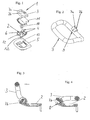
- Ein Ausführungsbeispiel der Erfindung ist in den Zeichnungen dargestellt und im Folgenden näher beschrieben. Es zeigt:
- Figur 1
- eine erfindungsgemäße Verzurröse In Explosionsdarstellung;
- Figur 2
- den Bügel aus
Figur 1 in Vergrößerter Darstellung; - Figur 3
- einen erfindungsgemäßen Halter mit Bügel in Gebrauchslage geschnitten;
- Figur 4
- desgleichen aus
Figur 3 in Nichtgebrauchslage; - Figur 5
- einen erfindungsgemäßen Halter mit Bügel in der Gebrauchslage in Draufsicht;
- Figur 6
- desgleichen aus
Figur 5 in Nichtgebrauchslage von schräg Oben gesehen; - Figur 7
- desgleichen aus
Figur 6 von schräg unten gesehen. - In den Figuren ist eine Verzurröse 1 für den Laderaum eines Kraftfahrzeuges gezeigt. Diese besteht im Ausführungsbeispiel aus einem Halter 2 aus Stahlblech mit einem im Halter 2 aus einer Nichtgebrauchslage in einer Gebrauchslage verschwenkbaren ringförmigen Bügel 3 ebenfalls aus Stahl. Der Halter 2 weist einen den Bügel 3 umfänglich umgreifenden Bereich 4 auf. In der Montagesolllage sind der Halter 2 und der Bügel 3 innerhalb eines Rahmenteils 5 im Boden des Laderaums eines Kraftfahrzeugs angeordnet und befestigt. Der Bügel 3 dient zum Verzurren von Spanngurten, Halteseilen, Haltenetzen oder dergleichen Ladesicherungselementen auf oder an der Ladefläche des Laderaums des Kraftfahrzeugs.
- Erfindungsgemäß weist der Halter 2 in seinem dem Bügel 3 umfänglich umgreifenden Bereich 4 eine Ausnehmung 6 auf. Innerhalb der Ausnehmung 6 ist ein radial vom Bügel 3 abragender Vorsprung 7a, 7b angeordnet. Alternativ und wie in den Figuren gezeigt, können auch zwei benachbarte Vorsprünge 7a, 7b angeordnet sein. Jeder Vorsprung 7a, 7b liegt dabei in der Gebrauchslage an einer Innenrandkante 8 der Ausnehmung 6 an, um ein Verschwenken des Bügels 3 über die Gebrauchslage hinaus und ein dadurch bedingtes Beschädigen des Rahmenteils 5 oder Teile der Ladebodenverkleidung zu verhindern.
- Der Bügel 3 besteht dabei aus einem zu einer Ringform gebogenem Drahtabschnitt mit einer im Bereich der Ausnehmung 6 angeordneten Stoßstelle 9. Dabei ist an jedem Ende des Drahtabschnitts an beziehungsweise nahe der Stoßstelle 9 jeweils ein Vorsprung 7a beziehungsweise 7b innerhalb der Ausnehmung 6 angeordnet. Die Vorsprünge 7a, 7b verschwenken mit dem Bügel 3 beim Verschwenken des Bügels 3 aus der Nichtgebrauchslage in die Gebrauchslage. Nach Erreichen der Gebrauchslage liegen die Vorsprünge 7a, 7b an der Innenrandkante 8 der Ausnehmung 6 an, die somit eine Wegbegrenzung für den verschwenkbaren Bügel 3 bildet und ein Verschwenken des Bügels 3 über die Gebrauchslage hinaus verhindert.
- Alternativ und in den Figuren nicht gezeigt, kann auch nur an oder nahe der Stoßstelle an einem Ende des Drahtabschnitts ein Vorsprung 7a oder 7b angeordnet sein.
- Die Ringform des Bügels 3 weist einen ersten geraden Bereich auf, der vom Halter 2 umgriffen ist (bei 4). Zudem weist der Halter 3 einen zweiten, etwa zum ersten geraden Bereich parallelen Bereich auf.
- Die Länge der Ausnehmung 6 ist in Axialrichtung der ersten Geraden gesehen, geringfügig größer als die Länge der Vorsprünge 7a, 7b. Hierdurch ist ein beispielsweise stoffschlüssiges Verbinden der beiden Enden, welches mit zusätzlichen Kosten verbunden ist, nicht mehr nötig, da die Vorsprünge bei axial zur ersten Geraden auftretenden auf den Bügel 3 einwirkenden Kräften innerhalb der Ausnehmung angeordnet sind und ein Aufbiegen der Enden des Drahtbügels verhindern, da sie an den die Länge der Ausnehmung 6 begrenzenden Seitenrandkanten der Ausnehmung 6 anliegen beziehungsweise anstoßen.
- Wie insbesondere aus
Figur 1 ersichtlich, ist ein Rahmenteil 5 vorgesehen, welches den Halter 2 unterseitig und außenseitig derart umgreift, dass der Halter 2 und das Rahmenteil in der Nichtgebrauchslage eine Ebene bilden. Dabei sind der Halter 2 und das Rahmenteil 5 mit dem Ladeboden verbunden. Im Ausführungsbeispiel sind der Halter 2 und das Rahmenteil 5 mit dem Ladeboden verschraubt (bei 10). Zur optischen Abdeckung dieser Verschraubung 10 ist in der Zusammenbaulage der Verzurröse 1 eine Zierkappe 11 den Halter 2 und die Schraube 10 verdeckend innerhalb der Verzurröse 1 vorgesehen. Der Halter 2 besteht dabei aus einer Platte und einem längsseitig von der Platte abragenden Bereich, der den Bügel 3 umgreift. - Als Toleranzausgleich und um eine mögliche Geräuschentwicklung, wie beispielsweise Klappern zu verhindern, ist an dem Halter 2 innerhalb des den Bügel 3 umfänglich umgreifenden Bereiches 4 ein elastisches Mittel in Form eines Kunststoffschlauchabschnittes 13 angeordnet. Im Ausführungsbeispiel entspricht die Länge des Kunststoffschlauchabschnittes 13 der Länge des umgriffenen Bereiches 4 des Bügels 3 und ist gemeinsam mit dem Bügel 3 vom Halter umgriffen.
- Die Erfindung ist nicht auf das Ausführungsbeispiel beschränkt, sondern im Rahmen der Offenbarung vielfach variabel.
- Alle neuen, in der Beschreibung und/oder Zeichnung offenbarten Einzel- und Kombinationsmerkmale werden als erfindungswesentlich angesehen.
Claims (8)
- Verzurröse (1) für den Laderaum eines Kraftfahrzeuges, zumindest bestehend aus einem Halter (2) mit einem im Halter (2) aus einer Nichtgebrauchslage in eine Gebrauchslage verschwenkbaren etwa ringförmigen Bügel (3), wobei der Halter (2) einen den Bügel (3) umfänglich umgreifenden Bereich (4) aufweist und Halter (2) und Bügel (3) vorzugsweise innerhalb eines Rahmenteils (5) im Boden des Laderaums angeordnet und befestigt sind, wobei der Bügel (3) zum Verzurren von Spanngurten, Halteseilen, Haltenetzen oder dergleichen Ladesicherungselementen auf oder an der Ladefläche dient, dadurch gekennzeichnet, dass der Halter (2) in seinem den Bügel (3) umfänglich umgreifenden Bereich (4) eine Ausnehmung (6) aufweist, innerhalb derer ein an dem Bügel (3) radial abragender Vorsprung (7a,7b) angeordnet oder ausgebildet ist, wobei der Vorsprung (7a,7b) in der Gebrauchslage an einer Innenrandkante (8) der Ausnehmung (6) anliegt.
- Verzurröse (1) nach Anspruch 1, dadurch gekennzeichnet, dass der Bügel (3) aus einem zu einer Ringform gebogenen Drahtabschnitt besteht, dessen Stoßstelle (9) im Bereich der Ausnehmung (6) angeordnet ist, wobei der Vorsprung (7a oder 7b) an einem der Enden des Drahtabschnitts an oder nahe an der Stoßstelle (9) innerhalb der Ausnehmung (6) angeordnet ist.
- Verzurröse (1) nach Anspruch 1, dadurch gekennzeichnet, dass der Bügel (3) aus einem zu einer Ringform gebogenen Drahtabschnitt besteht, dessen Stoßstelle (9) im Bereich der Ausnehmung (6) angeordnet ist, wobei an jedem Ende des Drahtabschnitts an oder nahe an der Stoßstelle (9) innerhalb der Ausnehmung (6) ein Vorsprung (7a oder 7b) angeordnet ist.
- Verzurröse (1) nach einem der Ansprüche 1 bis 3, dadurch gekennzeichnet, dass die Breite der Ausnehmung (6) geringfügig größer ist als die Breite des oder der Vorsprünge (7a, 7b).
- Verzurröse (1) nach einem der Ansprüche 1 bis 4, dadurch gekennzeichnet, dass das Rahmenteil (5) den Halter (2) unterseitig und außenseitig derart umgreift, dass der Halter (2) und das Rahmenteil (5) in der Nichtgebrauchslage eine Ebene bilden, wobei der Halter (2) und das Rahmenteil (5) mit dem Ladeboden verbunden sind, beispielsweise mittels Verschrauben (bei 10), und der Halter (2) in der Zusammenbaulage mit einer Zierkappe (11) abgedeckt ist.
- Verzurröse (1) nach einem der Ansprüche 1 bis 5, dadurch gekennzeichnet, dass am Halter (2) Verdrehsicherungselemente in Form von am Bügel (3) gegenüberliegenden Bereich angeordneten Haltevorsprüngen (12) ausgebildet sind, die in entsprechende Ausnehmungen am Ladeboden eingreifen.
- Verzurröse (1) nach einem der Ansprüche 1 bis 6, dadurch gekennzeichnet, dass am Halter (2) innerhalb des den Bügel (3) umfänglich umgreifenden Bereiches (4) ein elastisches Mittel angeordnet ist.
- Verzurröse (1) nach Anspruch 7, dadurch gekennzeichnet, dass das elastische Mittel durch einen Kunststoffschlauchabschnitt (13) gebildet ist, dessen Länge der Länge des umgriffenen Bereichs (4) entspricht und der parallel zum Bügel (3) verlaufend vom Halter (2) umgriffen ist.
Applications Claiming Priority (1)
| Application Number | Priority Date | Filing Date | Title |
|---|---|---|---|
| DE202011001237U DE202011001237U1 (de) | 2011-01-07 | 2011-01-07 | Verzurröse |
Publications (2)
| Publication Number | Publication Date |
|---|---|
| EP2474445A1 true EP2474445A1 (de) | 2012-07-11 |
| EP2474445B1 EP2474445B1 (de) | 2016-04-06 |
Family
ID=43734997
Family Applications (1)
| Application Number | Title | Priority Date | Filing Date |
|---|---|---|---|
| EP12000025.2A Active EP2474445B1 (de) | 2011-01-07 | 2012-01-03 | Verzurröse |
Country Status (6)
| Country | Link |
|---|---|
| US (1) | US8388286B2 (de) |
| EP (1) | EP2474445B1 (de) |
| CN (1) | CN102700455B (de) |
| DE (1) | DE202011001237U1 (de) |
| ES (1) | ES2567702T3 (de) |
| PL (1) | PL2474445T3 (de) |
Cited By (2)
| Publication number | Priority date | Publication date | Assignee | Title |
|---|---|---|---|---|
| DE102017209502A1 (de) | 2017-06-06 | 2018-12-06 | Volkswagen Aktiengesellschaft | Befestigungseinrichtung, Verfahren zur Herstellung einer Befestigungseinrichtung und Kraftfahrzeug |
| DE102017218537A1 (de) | 2017-10-17 | 2019-04-18 | Volkswagen Aktiengesellschaft | Befestigungseinrichtung, Verfahren zur Herstellung einer Befestigungseinrichtung und Kraftfahrzeug |
Families Citing this family (12)
| Publication number | Priority date | Publication date | Assignee | Title |
|---|---|---|---|---|
| FR2975056B1 (fr) * | 2011-05-11 | 2014-03-21 | Altia Group | Dispositif d'attache de bagage pour vehicule |
| US9132916B2 (en) * | 2012-10-30 | 2015-09-15 | The Boeing Company | Aircraft deployment and retrieval of unmanned aerial vehicles |
| US9511705B1 (en) | 2015-01-28 | 2016-12-06 | Donald S. Egigian | Front mounting, flush, anchor point |
| US9610887B1 (en) | 2015-09-11 | 2017-04-04 | Ford Global Technologies, Llc | Cargo tie-down assembly |
| CN105253065A (zh) * | 2015-11-12 | 2016-01-20 | 张家港孚冈汽车部件有限公司 | 汽车行李箱货物捆绑器 |
| US11097645B2 (en) * | 2018-05-24 | 2021-08-24 | Illinois Tool Works Inc. | Tie down assembly |
| CN111017071A (zh) * | 2019-08-15 | 2020-04-17 | 南京依维柯汽车有限公司 | 一种厢式货车可折d形系固钩和系固点强度显式计算及评价方法 |
| US11524619B2 (en) | 2019-11-26 | 2022-12-13 | Fca Us Llc | Tie-down loop assembly |
| US11135963B1 (en) | 2020-07-06 | 2021-10-05 | Bestop Bullring, Llc | Tie down anchor for pickup truck |
| JP6991608B2 (ja) * | 2020-08-11 | 2022-01-12 | ジー・オー・ピー株式会社 | 運搬台車 |
| US12077089B2 (en) | 2021-04-21 | 2024-09-03 | Illinois Tool Works Inc. | Position clutch ring system |
| DE102023101270A1 (de) * | 2023-01-19 | 2024-07-25 | Bayerische Motoren Werke Aktiengesellschaft | Befestigungsanordnung für ein Kraftfahrzeug, Kraftfahrzeug mit derartiger Befestigungsanordnung und Verfahren zur Montage der Befestigungsanordnung an dem Kraftfahrzeug |
Citations (4)
| Publication number | Priority date | Publication date | Assignee | Title |
|---|---|---|---|---|
| US5774948A (en) * | 1997-04-04 | 1998-07-07 | Creative Wire & Tube Forming, Inc. | Tie-down ring |
| WO2001072548A1 (en) * | 2000-03-29 | 2001-10-04 | Southco, Inc. | Tie-down hoop |
| DE10130202A1 (de) * | 2001-06-22 | 2003-01-09 | Daimler Chrysler Ag | Verzurrösenanordnung an einem Kraftfahrzeug-Laderaumboden |
| DE102005026964A1 (de) * | 2005-06-10 | 2006-12-14 | Trade World One Gmbh | Gurtöse |
Family Cites Families (6)
| Publication number | Priority date | Publication date | Assignee | Title |
|---|---|---|---|---|
| US4005904A (en) * | 1975-06-24 | 1977-02-01 | Sigmatex, A.G. | Run through bracket |
| US4850769A (en) * | 1987-06-08 | 1989-07-25 | James E. Irvin | Tie-down device |
| US5109573A (en) * | 1990-09-27 | 1992-05-05 | Smith Corona Corporation | Brake mechanism for a pivotable character display |
| CN2196051Y (zh) * | 1994-03-22 | 1995-05-03 | 黄汉卿 | 改良结构的货物固定架 |
| US5788437A (en) * | 1996-01-16 | 1998-08-04 | Stahl.Scott Fetzer Company | Cargo tie down assembly and method of use |
| ATE300269T1 (de) * | 1999-03-10 | 2005-08-15 | Delta Tooling Co Ltd | Blockiervorrichtung |
-
2011
- 2011-01-07 DE DE202011001237U patent/DE202011001237U1/de not_active Expired - Lifetime
-
2012
- 2012-01-03 EP EP12000025.2A patent/EP2474445B1/de active Active
- 2012-01-03 PL PL12000025.2T patent/PL2474445T3/pl unknown
- 2012-01-03 ES ES12000025.2T patent/ES2567702T3/es active Active
- 2012-01-06 CN CN201210066182.3A patent/CN102700455B/zh not_active Expired - Fee Related
- 2012-01-17 US US13/343,542 patent/US8388286B2/en active Active
Patent Citations (4)
| Publication number | Priority date | Publication date | Assignee | Title |
|---|---|---|---|---|
| US5774948A (en) * | 1997-04-04 | 1998-07-07 | Creative Wire & Tube Forming, Inc. | Tie-down ring |
| WO2001072548A1 (en) * | 2000-03-29 | 2001-10-04 | Southco, Inc. | Tie-down hoop |
| DE10130202A1 (de) * | 2001-06-22 | 2003-01-09 | Daimler Chrysler Ag | Verzurrösenanordnung an einem Kraftfahrzeug-Laderaumboden |
| DE102005026964A1 (de) * | 2005-06-10 | 2006-12-14 | Trade World One Gmbh | Gurtöse |
Cited By (2)
| Publication number | Priority date | Publication date | Assignee | Title |
|---|---|---|---|---|
| DE102017209502A1 (de) | 2017-06-06 | 2018-12-06 | Volkswagen Aktiengesellschaft | Befestigungseinrichtung, Verfahren zur Herstellung einer Befestigungseinrichtung und Kraftfahrzeug |
| DE102017218537A1 (de) | 2017-10-17 | 2019-04-18 | Volkswagen Aktiengesellschaft | Befestigungseinrichtung, Verfahren zur Herstellung einer Befestigungseinrichtung und Kraftfahrzeug |
Also Published As
| Publication number | Publication date |
|---|---|
| EP2474445B1 (de) | 2016-04-06 |
| DE202011001237U1 (de) | 2011-03-10 |
| PL2474445T3 (pl) | 2016-10-31 |
| US8388286B2 (en) | 2013-03-05 |
| US20120174344A1 (en) | 2012-07-12 |
| CN102700455A (zh) | 2012-10-03 |
| ES2567702T3 (es) | 2016-04-26 |
| CN102700455B (zh) | 2015-11-25 |
Similar Documents
| Publication | Publication Date | Title |
|---|---|---|
| EP2474445B1 (de) | Verzurröse | |
| DE69921313T2 (de) | Halteanordnung für ein stabteil | |
| DE102006017287A1 (de) | Spanner für einen Endlostrieb | |
| DE102014010633A1 (de) | Klappe für ein Fahrzeug | |
| DE102017117758B4 (de) | Ösen-Einsatz, Wand mit eingebautem Ösen-Einsatz sowie Verfahren zum Montieren des Ösen-Einsatzes | |
| DE202008002838U1 (de) | Spannschloss zum Festzurren von Ladungen auf Fahrzeugen | |
| DE102008011769A1 (de) | Spannschloss zum Festzurren von Ladungen auf Fahrzeugen | |
| WO2004061355A1 (de) | Halteklemme | |
| EP3453540B1 (de) | Radschale zur aufnahme eines rads eines zweirädrigen fahrzeugs | |
| DE4000722A1 (de) | Verankerung fuer zurrmittel | |
| WO2012000577A1 (de) | Schnellverschluss für ein fahrzeugfestes ende eines sicherheitsgurtes in einem kraftfahrzeug | |
| DE202007010263U1 (de) | Gurtspanner | |
| DE202011050499U1 (de) | Spannschloss für Zurrketten oder Zurrbänder zum Festzurren von Ladungen auf Fahrzeugen | |
| EP2428397B1 (de) | Lochprofilschiene | |
| DE102011116945B3 (de) | Befestigungselement zur Befestigung eines Airbags und ein Klemmelement zur Befestigung eines schlauchförmig gerollten oder gefalteten Airbags | |
| DE102006039485A1 (de) | Ausgleichsgewicht für den Unwuchtausgleich eines Fahrzeugrades | |
| DE10117432C2 (de) | Anordnung zur Ladegutsicherung | |
| DE102015010788A1 (de) | Gurtwelle für einen Gurtstraffer sowie Gurtstraffer eines Sicherheitsgurtsystems | |
| EP4368804B1 (de) | Anschlagpuffer mit einer verdrehsicherung | |
| DE102015109172B4 (de) | Nutzfahrzeugaufbau mit einer Plane, Nutzfahrzeug mit einem derartigen Nutzfahrzeugaufbau und Verfahren zur Herstellung eines Nutzfahrzeugaufbaus | |
| DE102012210835A1 (de) | Rohrbefestigungselement, System zur Rohrbefestigung und Verfahren zur Befestigung eines Rohres | |
| DE202006012954U1 (de) | Ausgleichsgewicht für den Unwuchtausgleich eines Fahrzeugrades | |
| DE102020109274B3 (de) | Zurröse mit Mittelstück zur Anordnung an einer Ladefläche eines Transportfahrzeuges | |
| DE102009032557A1 (de) | Spannvorrichtung für einen Zugmitteltrieb eines Kraftfahrzeuges | |
| EP3566901B1 (de) | Zurrpunkt mit montagestellung |
Legal Events
| Date | Code | Title | Description |
|---|---|---|---|
| PUAI | Public reference made under article 153(3) epc to a published international application that has entered the european phase |
Free format text: ORIGINAL CODE: 0009012 |
|
| AK | Designated contracting states |
Kind code of ref document: A1 Designated state(s): AL AT BE BG CH CY CZ DE DK EE ES FI FR GB GR HR HU IE IS IT LI LT LU LV MC MK MT NL NO PL PT RO RS SE SI SK SM TR |
|
| AX | Request for extension of the european patent |
Extension state: BA ME |
|
| 17P | Request for examination filed |
Effective date: 20120808 |
|
| GRAP | Despatch of communication of intention to grant a patent |
Free format text: ORIGINAL CODE: EPIDOSNIGR1 |
|
| INTG | Intention to grant announced |
Effective date: 20151007 |
|
| GRAS | Grant fee paid |
Free format text: ORIGINAL CODE: EPIDOSNIGR3 |
|
| GRAA | (expected) grant |
Free format text: ORIGINAL CODE: 0009210 |
|
| AK | Designated contracting states |
Kind code of ref document: B1 Designated state(s): AL AT BE BG CH CY CZ DE DK EE ES FI FR GB GR HR HU IE IS IT LI LT LU LV MC MK MT NL NO PL PT RO RS SE SI SK SM TR |
|
| REG | Reference to a national code |
Ref country code: GB Ref legal event code: FG4D Free format text: NOT ENGLISH |
|
| REG | Reference to a national code |
Ref country code: AT Ref legal event code: REF Ref document number: 787387 Country of ref document: AT Kind code of ref document: T Effective date: 20160415 Ref country code: CH Ref legal event code: EP |
|
| REG | Reference to a national code |
Ref country code: ES Ref legal event code: FG2A Ref document number: 2567702 Country of ref document: ES Kind code of ref document: T3 Effective date: 20160426 |
|
| REG | Reference to a national code |
Ref country code: IE Ref legal event code: FG4D Free format text: LANGUAGE OF EP DOCUMENT: GERMAN |
|
| REG | Reference to a national code |
Ref country code: DE Ref legal event code: R096 Ref document number: 502012006536 Country of ref document: DE |
|
| REG | Reference to a national code |
Ref country code: NL Ref legal event code: FP |
|
| REG | Reference to a national code |
Ref country code: LT Ref legal event code: MG4D |
|
| PG25 | Lapsed in a contracting state [announced via postgrant information from national office to epo] |
Ref country code: LT Free format text: LAPSE BECAUSE OF FAILURE TO SUBMIT A TRANSLATION OF THE DESCRIPTION OR TO PAY THE FEE WITHIN THE PRESCRIBED TIME-LIMIT Effective date: 20160406 Ref country code: IS Free format text: LAPSE BECAUSE OF FAILURE TO SUBMIT A TRANSLATION OF THE DESCRIPTION OR TO PAY THE FEE WITHIN THE PRESCRIBED TIME-LIMIT Effective date: 20160806 Ref country code: FI Free format text: LAPSE BECAUSE OF FAILURE TO SUBMIT A TRANSLATION OF THE DESCRIPTION OR TO PAY THE FEE WITHIN THE PRESCRIBED TIME-LIMIT Effective date: 20160406 Ref country code: NO Free format text: LAPSE BECAUSE OF FAILURE TO SUBMIT A TRANSLATION OF THE DESCRIPTION OR TO PAY THE FEE WITHIN THE PRESCRIBED TIME-LIMIT Effective date: 20160706 |
|
| PG25 | Lapsed in a contracting state [announced via postgrant information from national office to epo] |
Ref country code: SE Free format text: LAPSE BECAUSE OF FAILURE TO SUBMIT A TRANSLATION OF THE DESCRIPTION OR TO PAY THE FEE WITHIN THE PRESCRIBED TIME-LIMIT Effective date: 20160406 Ref country code: RS Free format text: LAPSE BECAUSE OF FAILURE TO SUBMIT A TRANSLATION OF THE DESCRIPTION OR TO PAY THE FEE WITHIN THE PRESCRIBED TIME-LIMIT Effective date: 20160406 Ref country code: LV Free format text: LAPSE BECAUSE OF FAILURE TO SUBMIT A TRANSLATION OF THE DESCRIPTION OR TO PAY THE FEE WITHIN THE PRESCRIBED TIME-LIMIT Effective date: 20160406 Ref country code: PT Free format text: LAPSE BECAUSE OF FAILURE TO SUBMIT A TRANSLATION OF THE DESCRIPTION OR TO PAY THE FEE WITHIN THE PRESCRIBED TIME-LIMIT Effective date: 20160808 Ref country code: HR Free format text: LAPSE BECAUSE OF FAILURE TO SUBMIT A TRANSLATION OF THE DESCRIPTION OR TO PAY THE FEE WITHIN THE PRESCRIBED TIME-LIMIT Effective date: 20160406 Ref country code: GR Free format text: LAPSE BECAUSE OF FAILURE TO SUBMIT A TRANSLATION OF THE DESCRIPTION OR TO PAY THE FEE WITHIN THE PRESCRIBED TIME-LIMIT Effective date: 20160707 |
|
| REG | Reference to a national code |
Ref country code: DE Ref legal event code: R097 Ref document number: 502012006536 Country of ref document: DE |
|
| REG | Reference to a national code |
Ref country code: FR Ref legal event code: PLFP Year of fee payment: 6 |
|
| PG25 | Lapsed in a contracting state [announced via postgrant information from national office to epo] |
Ref country code: DK Free format text: LAPSE BECAUSE OF FAILURE TO SUBMIT A TRANSLATION OF THE DESCRIPTION OR TO PAY THE FEE WITHIN THE PRESCRIBED TIME-LIMIT Effective date: 20160406 Ref country code: SK Free format text: LAPSE BECAUSE OF FAILURE TO SUBMIT A TRANSLATION OF THE DESCRIPTION OR TO PAY THE FEE WITHIN THE PRESCRIBED TIME-LIMIT Effective date: 20160406 Ref country code: EE Free format text: LAPSE BECAUSE OF FAILURE TO SUBMIT A TRANSLATION OF THE DESCRIPTION OR TO PAY THE FEE WITHIN THE PRESCRIBED TIME-LIMIT Effective date: 20160406 Ref country code: RO Free format text: LAPSE BECAUSE OF FAILURE TO SUBMIT A TRANSLATION OF THE DESCRIPTION OR TO PAY THE FEE WITHIN THE PRESCRIBED TIME-LIMIT Effective date: 20160406 |
|
| PLBE | No opposition filed within time limit |
Free format text: ORIGINAL CODE: 0009261 |
|
| PLAA | Information modified related to event that no opposition was filed |
Free format text: ORIGINAL CODE: 0009299DELT |
|
| PLBE | No opposition filed within time limit |
Free format text: ORIGINAL CODE: 0009261 |
|
| PG25 | Lapsed in a contracting state [announced via postgrant information from national office to epo] |
Ref country code: SM Free format text: LAPSE BECAUSE OF FAILURE TO SUBMIT A TRANSLATION OF THE DESCRIPTION OR TO PAY THE FEE WITHIN THE PRESCRIBED TIME-LIMIT Effective date: 20160406 |
|
| 26N | No opposition filed |
Effective date: 20170110 |
|
| R26N | No opposition filed (corrected) |
Effective date: 20170110 |
|
| RAP2 | Party data changed (patent owner data changed or rights of a patent transferred) |
Owner name: SODECIA KEMMERICH GMBH |
|
| REG | Reference to a national code |
Ref country code: NL Ref legal event code: PD Owner name: SODECIA KEMMERICH GMBH; DE Free format text: DETAILS ASSIGNMENT: CHANGE OF OWNER(S), ASSIGNMENT; FORMER OWNER NAME: GEBR. KEMMERICH GMBH Effective date: 20170307 |
|
| REG | Reference to a national code |
Ref country code: DE Ref legal event code: R081 Ref document number: 502012006536 Country of ref document: DE Owner name: SODECIA AUTOMOTIVE EUROPE GMBH, DE Free format text: FORMER OWNER: GEBR. KEMMERICH GMBH, 57439 ATTENDORN, DE Ref country code: DE Ref legal event code: R082 Ref document number: 502012006536 Country of ref document: DE Representative=s name: PATENTANWAELTE KOECHLING, DOERING PARTG MBB, DE Ref country code: DE Ref legal event code: R081 Ref document number: 502012006536 Country of ref document: DE Owner name: SODECIA KEMMERICH GMBH, DE Free format text: FORMER OWNER: GEBR. KEMMERICH GMBH, 57439 ATTENDORN, DE |
|
| PG25 | Lapsed in a contracting state [announced via postgrant information from national office to epo] |
Ref country code: SI Free format text: LAPSE BECAUSE OF FAILURE TO SUBMIT A TRANSLATION OF THE DESCRIPTION OR TO PAY THE FEE WITHIN THE PRESCRIBED TIME-LIMIT Effective date: 20160406 Ref country code: BE Free format text: LAPSE BECAUSE OF NON-PAYMENT OF DUE FEES Effective date: 20170131 |
|
| REG | Reference to a national code |
Ref country code: DE Ref legal event code: R082 Ref document number: 502012006536 Country of ref document: DE Representative=s name: PATENTANWAELTE KOECHLING, DOERING PARTG MBB, DE Ref country code: DE Ref legal event code: R081 Ref document number: 502012006536 Country of ref document: DE Owner name: SODECIA AUTOMOTIVE EUROPE GMBH, DE Free format text: FORMER OWNER: SODECIA KEMMERICH GMBH, 57439 ATTENDORN, DE |
|
| REG | Reference to a national code |
Ref country code: GB Ref legal event code: 732E Free format text: REGISTERED BETWEEN 20170803 AND 20170809 |
|
| REG | Reference to a national code |
Ref country code: CH Ref legal event code: PL |
|
| REG | Reference to a national code |
Ref country code: NL Ref legal event code: PD Owner name: SODECIA AUTOMOTIVE EUROPE GMBH; DE Free format text: DETAILS ASSIGNMENT: CHANGE OF OWNER(S), ASSIGNMENT; FORMER OWNER NAME: SODECIA KEMMERICH GMBH Effective date: 20170711 |
|
| PG25 | Lapsed in a contracting state [announced via postgrant information from national office to epo] |
Ref country code: MC Free format text: LAPSE BECAUSE OF FAILURE TO SUBMIT A TRANSLATION OF THE DESCRIPTION OR TO PAY THE FEE WITHIN THE PRESCRIBED TIME-LIMIT Effective date: 20160406 |
|
| PG25 | Lapsed in a contracting state [announced via postgrant information from national office to epo] |
Ref country code: LI Free format text: LAPSE BECAUSE OF NON-PAYMENT OF DUE FEES Effective date: 20170131 Ref country code: CH Free format text: LAPSE BECAUSE OF NON-PAYMENT OF DUE FEES Effective date: 20170131 |
|
| REG | Reference to a national code |
Ref country code: IE Ref legal event code: MM4A |
|
| REG | Reference to a national code |
Ref country code: ES Ref legal event code: PC2A Owner name: SODECIA AUTOMOTIVE EUROPE GMBH Effective date: 20171114 |
|
| PG25 | Lapsed in a contracting state [announced via postgrant information from national office to epo] |
Ref country code: LU Free format text: LAPSE BECAUSE OF NON-PAYMENT OF DUE FEES Effective date: 20170103 |
|
| REG | Reference to a national code |
Ref country code: FR Ref legal event code: TP Owner name: SODECIA AUTOMOTIVE EUROPE GMBH, DE Effective date: 20171120 |
|
| REG | Reference to a national code |
Ref country code: FR Ref legal event code: PLFP Year of fee payment: 7 |
|
| REG | Reference to a national code |
Ref country code: BE Ref legal event code: MM Effective date: 20170131 |
|
| PG25 | Lapsed in a contracting state [announced via postgrant information from national office to epo] |
Ref country code: IE Free format text: LAPSE BECAUSE OF NON-PAYMENT OF DUE FEES Effective date: 20170103 |
|
| REG | Reference to a national code |
Ref country code: AT Ref legal event code: MM01 Ref document number: 787387 Country of ref document: AT Kind code of ref document: T Effective date: 20170103 |
|
| PG25 | Lapsed in a contracting state [announced via postgrant information from national office to epo] |
Ref country code: AT Free format text: LAPSE BECAUSE OF NON-PAYMENT OF DUE FEES Effective date: 20170103 |
|
| PG25 | Lapsed in a contracting state [announced via postgrant information from national office to epo] |
Ref country code: MT Free format text: LAPSE BECAUSE OF FAILURE TO SUBMIT A TRANSLATION OF THE DESCRIPTION OR TO PAY THE FEE WITHIN THE PRESCRIBED TIME-LIMIT Effective date: 20160406 |
|
| PG25 | Lapsed in a contracting state [announced via postgrant information from national office to epo] |
Ref country code: AL Free format text: LAPSE BECAUSE OF FAILURE TO SUBMIT A TRANSLATION OF THE DESCRIPTION OR TO PAY THE FEE WITHIN THE PRESCRIBED TIME-LIMIT Effective date: 20160406 |
|
| PG25 | Lapsed in a contracting state [announced via postgrant information from national office to epo] |
Ref country code: HU Free format text: LAPSE BECAUSE OF FAILURE TO SUBMIT A TRANSLATION OF THE DESCRIPTION OR TO PAY THE FEE WITHIN THE PRESCRIBED TIME-LIMIT; INVALID AB INITIO Effective date: 20120103 |
|
| PG25 | Lapsed in a contracting state [announced via postgrant information from national office to epo] |
Ref country code: BG Free format text: LAPSE BECAUSE OF FAILURE TO SUBMIT A TRANSLATION OF THE DESCRIPTION OR TO PAY THE FEE WITHIN THE PRESCRIBED TIME-LIMIT Effective date: 20160406 |
|
| PG25 | Lapsed in a contracting state [announced via postgrant information from national office to epo] |
Ref country code: CY Free format text: LAPSE BECAUSE OF NON-PAYMENT OF DUE FEES Effective date: 20160406 |
|
| PG25 | Lapsed in a contracting state [announced via postgrant information from national office to epo] |
Ref country code: MK Free format text: LAPSE BECAUSE OF FAILURE TO SUBMIT A TRANSLATION OF THE DESCRIPTION OR TO PAY THE FEE WITHIN THE PRESCRIBED TIME-LIMIT Effective date: 20160406 |
|
| PG25 | Lapsed in a contracting state [announced via postgrant information from national office to epo] |
Ref country code: TR Free format text: LAPSE BECAUSE OF FAILURE TO SUBMIT A TRANSLATION OF THE DESCRIPTION OR TO PAY THE FEE WITHIN THE PRESCRIBED TIME-LIMIT Effective date: 20160406 |
|
| PGFP | Annual fee paid to national office [announced via postgrant information from national office to epo] |
Ref country code: DE Payment date: 20210331 Year of fee payment: 10 |
|
| REG | Reference to a national code |
Ref country code: DE Ref legal event code: R119 Ref document number: 502012006536 Country of ref document: DE |
|
| PG25 | Lapsed in a contracting state [announced via postgrant information from national office to epo] |
Ref country code: DE Free format text: LAPSE BECAUSE OF NON-PAYMENT OF DUE FEES Effective date: 20220802 |
|
| PGFP | Annual fee paid to national office [announced via postgrant information from national office to epo] |
Ref country code: GB Payment date: 20240628 Year of fee payment: 13 |
|
| PGFP | Annual fee paid to national office [announced via postgrant information from national office to epo] |
Ref country code: FR Payment date: 20240628 Year of fee payment: 13 |
|
| PGFP | Annual fee paid to national office [announced via postgrant information from national office to epo] |
Ref country code: PL Payment date: 20240628 Year of fee payment: 13 |
|
| PGFP | Annual fee paid to national office [announced via postgrant information from national office to epo] |
Ref country code: NL Payment date: 20240722 Year of fee payment: 13 |
|
| PGFP | Annual fee paid to national office [announced via postgrant information from national office to epo] |
Ref country code: ES Payment date: 20240718 Year of fee payment: 13 |
|
| PGFP | Annual fee paid to national office [announced via postgrant information from national office to epo] |
Ref country code: CZ Payment date: 20240628 Year of fee payment: 13 |
|
| PGFP | Annual fee paid to national office [announced via postgrant information from national office to epo] |
Ref country code: IT Payment date: 20240731 Year of fee payment: 13 |
|
| PG25 | Lapsed in a contracting state [announced via postgrant information from national office to epo] |
Ref country code: CZ Free format text: LAPSE BECAUSE OF NON-PAYMENT OF DUE FEES Effective date: 20250103 |
|
| REG | Reference to a national code |
Ref country code: NL Ref legal event code: MM Effective date: 20250201 |
|
| GBPC | Gb: european patent ceased through non-payment of renewal fee |
Effective date: 20250103 |
|
| PG25 | Lapsed in a contracting state [announced via postgrant information from national office to epo] |
Ref country code: NL Free format text: LAPSE BECAUSE OF NON-PAYMENT OF DUE FEES Effective date: 20250201 |
|
| PG25 | Lapsed in a contracting state [announced via postgrant information from national office to epo] |
Ref country code: GB Free format text: LAPSE BECAUSE OF NON-PAYMENT OF DUE FEES Effective date: 20250103 |
|
| PG25 | Lapsed in a contracting state [announced via postgrant information from national office to epo] |
Ref country code: FR Free format text: LAPSE BECAUSE OF NON-PAYMENT OF DUE FEES Effective date: 20250131 |
|
| PG25 | Lapsed in a contracting state [announced via postgrant information from national office to epo] |
Ref country code: IT Free format text: LAPSE BECAUSE OF NON-PAYMENT OF DUE FEES Effective date: 20250103 |
|
| REG | Reference to a national code |
Ref country code: ES Ref legal event code: FD2A Effective date: 20260226 |
|
| PG25 | Lapsed in a contracting state [announced via postgrant information from national office to epo] |
Ref country code: ES Free format text: LAPSE BECAUSE OF NON-PAYMENT OF DUE FEES Effective date: 20250104 |