EP2474475B1 - Procédé et système pour ensemble de cône de ravitaillement - Google Patents
Procédé et système pour ensemble de cône de ravitaillement Download PDFInfo
- Publication number
- EP2474475B1 EP2474475B1 EP12150105.0A EP12150105A EP2474475B1 EP 2474475 B1 EP2474475 B1 EP 2474475B1 EP 12150105 A EP12150105 A EP 12150105A EP 2474475 B1 EP2474475 B1 EP 2474475B1
- Authority
- EP
- European Patent Office
- Prior art keywords
- refueling
- coupling
- drogue
- hose
- probe
- Prior art date
- Legal status (The legal status is an assumption and is not a legal conclusion. Google has not performed a legal analysis and makes no representation as to the accuracy of the status listed.)
- Active
Links
Images


Classifications
-
- B—PERFORMING OPERATIONS; TRANSPORTING
- B64—AIRCRAFT; AVIATION; COSMONAUTICS
- B64D—EQUIPMENT FOR FITTING IN OR TO AIRCRAFT; FLIGHT SUITS; PARACHUTES; ARRANGEMENT OR MOUNTING OF POWER PLANTS OR PROPULSION TRANSMISSIONS IN AIRCRAFT
- B64D39/00—Refuelling during flight
- B64D39/06—Connecting hose to aircraft; Disconnecting hose therefrom
-
- B—PERFORMING OPERATIONS; TRANSPORTING
- B64—AIRCRAFT; AVIATION; COSMONAUTICS
- B64D—EQUIPMENT FOR FITTING IN OR TO AIRCRAFT; FLIGHT SUITS; PARACHUTES; ARRANGEMENT OR MOUNTING OF POWER PLANTS OR PROPULSION TRANSMISSIONS IN AIRCRAFT
- B64D39/00—Refuelling during flight
- B64D39/04—Adaptations of hose construction
Definitions
- the field of the invention relates generally to in-flight refueling drogues, and more specifically, to a method and system for an air-refueling drogue that provides positive latch indication of a refueling probe, reduced force latching/detaching, measurement of hose tension at the drogue end instead of at the reel end, and transmission of hose tension measurement and positive latch indication to the hose reel control system.
- Such methods are used because power, including electrical, hydraulic, pneumatic power, is not available at the drogue to allow additional remote sensing to give positive indication and control of coupling. Batteries could be used, however batteries have capacity, heating, charging, and power life aspects to contend with.
- the other approach is to incorporate wires or optical fibers, or the like, in the aerial refueling hose. Both of these are undesirable from an operational complexity, durability, cost, and safety view.
- US 3,475,001 discloses a probe nozzle for use with a drogue for in-flight refueling of aircraft.
- US 5,906,336 discloses an apparatus and method for aerial refueling of an unmanned aerial vehicle.
- a method of operating a refueling drogue assembly includes inserting a refueling probe of a receiving aircraft into an opening of the refueling drogue assembly extending from a tanker aircraft, detecting a presence of the refueling probe in a predetermined position of the refueling drogue assembly, and engaging a latch member of the refueling drogue assembly to a complementary latch-receiving member of the refueling probe using an actuator.
- an aerial refueling system in another example, includes a refueling drogue coupling system configured to be extended from a tanker aircraft at a distal end of a refueling hose.
- the refueling drogue coupling system includes a coupling latch assembly including a latch member configured to matingly engage a complementary latch-receiving member of a refueling probe, the coupling latch assembly further configured to move the latch member from a first locked position to a second unlocked position using a latch member actuator, a hose tension control subsystem positioned in the tanker aircraft and coupled to a proximal end of the refueling hose opposite the distal end, and a drogue controller wirelessly communicatively coupled to a hose tension controller positioned in the tanker aircraft.
- Embodiments of the present invention provide a positive, deterministic, means of establishing if a receiver aircraft probe is coupled with a refueling drogue in order to allow the refueling systems hose reel control system to properly initiate hose tension regulation and prevent hazardous hose whip.
- the embodiments also provide a means of positively coupling the probe and drogue at low force levels, thus allowing operations across wider airspeed and altitude envelopes. Additionally, unambiguous disconnect (due to emergency, failure, etc.) may also be commanded from either the receiver or tanker aircraft.
- the embodiments provide direct measurement of hose load at the drogue, thereby alleviating problems caused by attempts to infer hose load at the drogue by measuring hose load at the hose reel (via load cells or hydraulic pressure) as is common in existing systems.
- embodiments of the present invention also permit a configuration where the receiver is in front of the tanker and the tanker follows. In this configuration the tanker pumps fuel up the hose to the receiver instead of the tanker pumping fuel down the hose to the following receiver.
- FIG. 1 is a side view of a refueling aircraft 100 with a refueling drogue assembly 102 deployed in accordance with an exemplary embodiment of the present invention.
- refueling drogue assembly 102 includes a refueling drogue basket 104 connected to a distal portion 106 of a refueling hose 108 that is in turn connected to aircraft 100.
- a hose reel 110 and a hose tension control system 112 are positioned on refueling aircraft 100.
- Hose tension control system 112 is configured to maintain forces, such as, but not limited to, aerodynamic drag, gravity, refueling probe, and dynamics, acting on refueling drogue assembly 102 balanced such that positional control of refueling drogue assembly 102 is maintained.
- refueling drogue basket 104 is unreeled from refueling aircraft 100 towards a receiver aircraft 114 (an aircraft to be refueled), such as, but not limited to, a fighter plane or a helicopter.
- a refueling probe 116 extends from receiver aircraft 114.
- Receiver aircraft 114 maneuvers refueling probe 116 to refueling drogue basket 104 and inserts refueling probe 116 into a rearward facing opening 118 of refueling drogue basket 104, at which point a refueling coupling (not shown in FIG. 1 ) "locks" onto refueling probe 116, and a transfer of fuel from refueling aircraft 100 to receiver aircraft 114 is conducted.
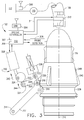
- FIG. 2 is a side view of refueling drogue assembly 102 (shown in FIG. 1 ) in accordance with an exemplary embodiment of the present invention.
- refueling drogue basket 104 is coupled to hose 108 through a basket collar 202 and a hose end connector 204.
- a ram air turbine 206 is used to generate electrical energy to power components of refueling drogue assembly 102.
- a gyroscopic effect of ram air turbine 206 during operation may also be used to positionally stabilize refueling drogue assembly 102.
- a cable 208 may be used to carry electrical energy and/or control signals between refueling drogue assembly 102 and aircraft 100.
- refueling drogue assembly 102 may be powered by a battery 210 carried onboard refueling drogue assembly 102.
- FIG. 3 is a side partially cutaway view of refueling drogue assembly 102 and refueling probe 116 in accordance with an exemplary embodiment of the present invention.
- refueling drogue assembly 102 includes a drogue controller 302 communicatively coupled to hose tension control system 112 using, in one embodiment, a wireless connection through a communications link 304 on refueling drogue assembly 102 and a link 306 at hose tension control system 112.
- Drogue controller 302 includes a processor 307 and a memory 309 for executing programmed instructions that perform the processes described herein.
- Refueling drogue assembly 102 also includes a refueling probe position sensor 308 configured to detect a presence of refueling probe 116 in refueling drogue assembly 102 and a position of refueling probe 116 relative to a predetermined inserted position of refueling probe 116 into refueling drogue assembly 102.
- a hose tension sensor 313 is communicatively coupled to hose tension control system 112 through a communication link 311.
- a latch assembly 310 includes a latch member 312 comprising a first pivot end 314, a locking roller 316, and a second pivot end 318.
- Latch assembly 310 also includes a toggle member 320 comprising an elongate body 322 having a first end 324 configured to engage a cam 326 pivotally coupled to latch member actuator 328 and a second end 330 comprising first 332 and second 334 orthogonally extending arms, said first arm 332 coupled to a latch assembly bias member 336, said second arm 334 coupled to said latch member 312.
- Locking roller 316 is configured to engage a complementary latch-receiving member 338 of refueling probe 116.
- latch-receiving member 338 comprises a circumferential groove formed in a probe collar 340 of refueling probe 116.
- hose 108 is played out from reel 110 by hose tension control system 112 automatically, upon input by an operator, or in response to preprogrammed instructions.
- receiving aircraft 114 approaches refueling drogue assembly 102 and inserts refueling probe 116 into opening 118.
- Latch assembly 310 is in an unlocked position such that actuator 328 is positioned in a retracted direction 342, which permits toggle member 320 to rotate in a clockwise direction 344, which in turn withdraws locking roller 316 away from longitudinal axis 346.
- Refueling probe 116 is able to be inserted using a relatively small amount of force.
- drogue controller 302 When refueling probe position sensor 308 detects the presence of refueling probe 116 at a predetermined position within refueling drogue assembly 102, drogue controller 302 commands latch assembly 310 to actuate thereby positioning locking roller 316 into engagement with latch-receiving member 338. This procedure, using refueling drogue assembly 102, permits insertion of refueling probe 116 with relatively less force and a positive determination that refueling probe 116 is in a proper position for latching the locking roller 316 onto latch-receiving member 338. Once refueling probe 116 is positively engaged with refueling drogue assembly 102, drogue controller 302 commands hose tension control system 112 to operate to control tension in hose 108.
- locking roller 316 is projected toward longitudinal axis 346 and presents an obstacle to entry of refueling probe 116 into refueling drogue assembly 102.
- obstacle is overcome by using a relatively greater force that forces toggle member 320 to work against bias member 336 to permit locking roller 316 to be pushed out of the path of refueling probe 116 by riding up inclined surface 348 of probe collar 340.
- tanker aircraft 100 or receiver aircraft 114 may send a disengage signal to drogue controller 302 to automatically disengage refueling probe 116 from refueling drogue assembly 102.
- drogue controller 302 sends a signal to latch member actuator 328 causes latch member actuator 328 to move to an unlock position that disengages locking roller 316 from latch-receiving member 338.
- Refueling probe 116 is then able to pull away from refueling drogue assembly 102 with a relatively small amount of disengagement force.
- Embodiments of the present invention positively determine, using a sensor, such as, but not limited to, a mechanical, an optical, or a proximity detecting switch, or by using a pulse waveform detected by an accelerometer, or a combination of the above, that the refueling probe is fully latched in the drogue coupling assembly, and by measuring hose load at the drogue assembly by means of a, for example, strain gauge transducer, and then transmitting these facts and measurements via wireless data link (RF, Electro-Optical, optical fiber, etc.) to a tanker hose tension control system for the hose tension control system to begin regulating hose tension prior to development of hazardous hose whip as well as improving the quality of regulation of hose tension during tanker and receiver relative motion via direct measurement of hose load at the drogue.
- a sensor such as, but not limited to, a mechanical, an optical, or a proximity detecting switch, or by using a pulse waveform detected by an accelerometer, or a combination of the above.
- processor refers to central processing units, microprocessors, microcontrollers, reduced instruction set circuits (RISC), application specific integrated circuits (ASIC), logic circuits, and any other circuit or processor capable of executing the functions described herein.
- RISC reduced instruction set circuits
- ASIC application specific integrated circuits
- the terms "software” and “firmware” are interchangeable, and include any computer program stored in memory for execution by processor 307, including RAM memory, ROM memory, EPROM memory, EEPROM memory, and non-volatile RAM (NVRAM) memory.
- RAM memory random access memory
- ROM memory read-only memory
- EPROM memory erasable programmable read-only memory
- EEPROM memory electrically erasable programmable read-only memory
- NVRAM non-volatile RAM
- the above-described embodiments of the disclosure may be implemented using computer programming or engineering techniques including computer software, firmware, hardware or any combination or subset thereof, wherein the technical effect is an improvement in the safety of probe and drogue aerial refueling operations and improvements in the operational envelope (expanded ranges of altitude and airspeed) over which refueling operations can be conducted.
- Any such resulting program, having computer-readable code means may be embodied or provided within one or more computer-readable media, thereby making a computer program product, i.e., an article of manufacture, according to the discussed embodiments of the disclosure.
- the computer-readable media may be, for example, but is not limited to, a fixed (hard) drive, diskette, optical disk, magnetic tape, semiconductor memory such as read-only memory (ROM), and/or any transmitting/receiving medium such as the Internet or other communication network or link.
- the article of manufacture containing the computer code may be made and/or used by executing the code directly from one medium, by copying the code from one medium to another medium, or by transmitting the code over a network.
- the above-described embodiments of a method and system of operating a drogue refueling system provides a cost-effective and reliable means ensuring a positive coupling of a refueling probe to a refueling drogue. More specifically, the method and system described herein facilitate coupling at relatively lower axial force. In addition, the above-described method and system facilitate supplying power to the drogue assembly. As a result, the method and system described herein facilitate coupling and uncoupling a refueling drogue assembly and refueling probe, directly measuring and transmitting hose load, and communicating system status and health in a cost-effective and reliable manner.
Landscapes
- Engineering & Computer Science (AREA)
- Aviation & Aerospace Engineering (AREA)
- Loading And Unloading Of Fuel Tanks Or Ships (AREA)
- Pipeline Systems (AREA)
- Quick-Acting Or Multi-Walled Pipe Joints (AREA)
- Arrangements For Transmission Of Measured Signals (AREA)
Claims (8)
- Système de couplage d'un entonnoir de ravitaillement (102), ledit système comprenant:un passage de fluide s'étendant d'une entrée de couplage à une sortie de couplage, ledit passage de fluide comprenant un siège de vanne entourant ledit passage de fluide à proximité de ladite sortie de couplage ;un ensemble de clapet de vanne comprenant un clapet de vanne configuré pour s'engager sur ledit siège afin d'empêcher un écoulement à travers ledit passage de fluide et un ensemble d'actionnement comprenant un élément de sollicitation ;un ensemble de verrou de couplage (310) couplé à ladite sortie de couplage,ledit ensemble de verrou de couplage comprenant un élément de verrouillage (312) configuré pour s'engager de manière conjuguée sur un élément récepteur de verrou complémentaire (338) d'une sonde de ravitaillement (116), ledit ensemble de verrou de couplage comprenant en outre un actionneur d'élément de verrouillage (328) couplé de manière opérationnelle audit élément de verrouillage pour permettre audit élément de verrouillage de se déplacer d'une première position verrouillée à une seconde position déverrouillée ;caractérisé en ce que ledit système comprend en outre :un capteur de position de sonde (308) configuré pour détecter une position de la sonde de ravitaillement ;un capteur de tension de tuyau (313) configuré pour mesurer une tension dans un tuyau (108) couplé à ladite entrée de couplage ; etun dispositif de commande d'entonnoir (302) positionné sur ledit système de couplage (102) de l'entonnoir de ravitaillement et couplé en communication avec ledit actionneur (328) de l'élément de verrouillage, ledit capteur de position de sonde (308) et ledit capteur de tension de tuyau (313).
- Système (102) selon la revendication 1, comprenant en outre un système d'alimentation électrique de l'entonnoir positionné sur ledit système de couplage de l'entonnoir de ravitaillement et configuré pour fournir de l'énergie audit système de couplage de l'entonnoir de ravitaillement.
- Système (102) selon la revendication 1, comprenant en outre un système d'alimentation électrique de l'entonnoir comprenant au moins l'une ou l'autre d'une turbine à air dynamique (206) et d'une batterie (210) et positionné sur ledit système de couplage de l'entonnoir de ravitaillement et un câble (208) couplé électriquement entre ledit système d'alimentation électrique de l'entonnoir et une alimentation électrique externe.
- Système (102) selon l'une quelconque des revendications précédentes, comprenant en outre un sous-système de commande de tension de tuyau (112) comprenant :un tuyau de ravitaillement (108) couplé en communication fluidique avec ledit passage d'écoulement ;une bobine (110) configurée pour tourner autour d'un axe afin de stocker et de déployer ledit tuyau de ravitaillement ; etun actionneur couplé pour entraîner ladite roue.
- Système (102) selon la revendication 4, dans lequel ledit sous-système de commande de tension de tuyau (112) est couplé en communication avec le dispositif de commande d'entonnoir (302) et configuré pour recevoir des signaux relatifs à la tension du tuyau venant du capteur de tension de tuyau (313).
- Système (102) selon l'une quelconque des revendications précédentes, dans lequel ledit ensemble de verrou de couplage (310) comprend un élément articulé (320) comprenant un corps allongé (322) ayant une première extrémité (324) configurée pour s'engager sur une came (326) couplée à pivotement avec ledit actionneur d'élément de verrou (328) et une seconde extrémité (330) comprenant des premier et second bras s'étendant orthogonalement (332, 334), ledit premier bras étant couplé à un élément de sollicitation (336) de l'ensemble de verrou, ledit second bras étant couplé audit élément de verrouillage (312).
- Système (102) selon l'une quelconque des revendications précédentes, dans lequel ledit ensemble de verrou de couplage (310) est configuré pour se verrouiller sur la sonde de ravitaillement (116) en utilisant une première quantité de force axiale lorsque ledit ensemble de verrou de couplage se trouve dans une dite position déverrouillée et pour se verrouiller sur la sonde de ravitaillement en utilisant une seconde quantité de force axiale lorsque ledit ensemble de verrou de couplage se trouve dans une dite position verrouillée, dans lequel ladite première quantité de force axiale est inférieure à ladite seconde quantité de force axiale.
- Système selon la revendication 7, dans la mesure où elle dépend de la revendication 6, dans lequel ledit ensemble de verrou de couplage (310) est configuré pour se verrouiller sur la sonde de ravitaillement (116) en utilisant une première quantité de force axiale qui est suffisante pour surmonter une force communiquée par ledit élément de sollicitation (336) de l'ensemble de verrou.
Applications Claiming Priority (1)
| Application Number | Priority Date | Filing Date | Title |
|---|---|---|---|
| US12/984,961 US8561947B2 (en) | 2011-01-05 | 2011-01-05 | Method and system for a refueling drogue assembly |
Publications (3)
| Publication Number | Publication Date |
|---|---|
| EP2474475A2 EP2474475A2 (fr) | 2012-07-11 |
| EP2474475A3 EP2474475A3 (fr) | 2013-03-27 |
| EP2474475B1 true EP2474475B1 (fr) | 2016-09-07 |
Family
ID=45444545
Family Applications (1)
| Application Number | Title | Priority Date | Filing Date |
|---|---|---|---|
| EP12150105.0A Active EP2474475B1 (fr) | 2011-01-05 | 2012-01-03 | Procédé et système pour ensemble de cône de ravitaillement |
Country Status (6)
| Country | Link |
|---|---|
| US (1) | US8561947B2 (fr) |
| EP (1) | EP2474475B1 (fr) |
| JP (1) | JP6055181B2 (fr) |
| CN (1) | CN102582839B (fr) |
| BR (1) | BR102012000150A2 (fr) |
| CA (1) | CA2762867C (fr) |
Families Citing this family (25)
| Publication number | Priority date | Publication date | Assignee | Title |
|---|---|---|---|---|
| US9469410B2 (en) * | 2011-07-22 | 2016-10-18 | Carleton Life Support Systems Inc. | Aerial refueling system, apparatus and methods |
| US9650138B2 (en) | 2012-03-30 | 2017-05-16 | W.Morrison Consulting Group, Inc. | Long range electric aircraft and method of operating same |
| US9340299B2 (en) | 2012-03-30 | 2016-05-17 | W. Morrison Consulting Group, Inc. | Long range electric aircraft and method of operating same |
| US9067689B2 (en) * | 2013-01-14 | 2015-06-30 | The Boeing Company | Aircraft refueling system and method of refueling an aircraft |
| US9085370B2 (en) | 2013-06-03 | 2015-07-21 | General Electric Company | Systems and methods for wireless data transfer during in-flight refueling of an aircraft |
| CN103738502B (zh) * | 2013-11-27 | 2016-02-24 | 中国航空工业集团公司西安飞机设计研究所 | 一种飞机空中受油装置地面检查转接设备 |
| CN103995538B (zh) * | 2014-05-12 | 2017-01-11 | 中国航空工业集团公司沈阳飞机设计研究所 | 一种基于图像识别的空中受油控制方法 |
| EP2952434B1 (fr) * | 2014-06-03 | 2019-03-20 | Airbus Defence and Space SA | Couplage de ravitaillement aérien pour la mesure des paramètres en vol |
| US9868526B2 (en) | 2014-10-15 | 2018-01-16 | W. Morrison Consulting Group, Inc. | Airborne drone delivery network and method of operating same |
| US10106274B2 (en) * | 2015-03-30 | 2018-10-23 | Sikorsky Aircraft Corporation | Tail sitter vehicle with aerial and ground refueling system |
| US9540115B2 (en) | 2015-04-28 | 2017-01-10 | Northrop Grumman Systems Corporation | Dual mode frangible refueling nozzle |
| US10053218B2 (en) | 2016-03-31 | 2018-08-21 | General Electric Company | System and method for positioning an unmanned aerial vehicle |
| US10618668B2 (en) * | 2016-09-06 | 2020-04-14 | Analytical Mechanics Associates, Inc. | Systems and apparatus for controlling movement of objects through a fluid |
| US10676189B1 (en) * | 2017-02-01 | 2020-06-09 | Lockheed Martin Corporation | Aircraft capture system and method |
| US10703501B2 (en) * | 2017-03-17 | 2020-07-07 | Analytical Mechanics Associates, Inc. | Drogue control systems and apparatus |
| GB2574078B (en) * | 2018-09-27 | 2020-05-20 | pitman James | Methods and systems for in-flight fuelling of aircraft |
| EP3686109B1 (fr) | 2019-01-24 | 2020-12-30 | AIRBUS HELICOPTERS DEUTSCHLAND GmbH | Appareil de transmission de fluide en route |
| GB2590696B (en) * | 2019-12-24 | 2022-06-08 | Cobham Mission Systems Wimborne Ltd | Air-to-air coupling |
| WO2021195274A1 (fr) * | 2020-03-25 | 2021-09-30 | Orbit Fab, Inc. | Interfaces de transfert de matériaux pour véhicules spatiaux, ainsi que systèmes et procédés associés |
| GB2593695A (en) | 2020-03-30 | 2021-10-06 | Cobham Mission Systems Wimborne Ltd | Air-to-air refuelling drogue assembly |
| EP3842345B1 (fr) * | 2020-10-29 | 2022-10-19 | Airbus Defence and Space, S.A.U. | Système actif de ravitaillement en vol et procédé pour générer des charges aérodynamiques radiales au niveau d'une extrémité de tuyau |
| WO2023287922A1 (fr) | 2021-07-14 | 2023-01-19 | Orbit Fab, Inc. | Interfaces de transfert de matériaux pour véhicules spatiaux, ainsi que systèmes et procédés associés |
| CN114655468A (zh) * | 2022-04-28 | 2022-06-24 | 西北工业大学 | 一种无人机自主空中加油的输油软管测量控制装置和方法 |
| CN115924159B (zh) * | 2023-03-10 | 2023-05-16 | 四川省天域航通科技有限公司 | 大型无人机智能指挥控制平台及其控制方法 |
| WO2025176755A1 (fr) * | 2024-02-23 | 2025-08-28 | Airbus Defence And Space, S.A.U. | Système de ravitaillement en vol et procédé d'alimentation de dispositifs du système associé |
Family Cites Families (32)
| Publication number | Priority date | Publication date | Assignee | Title |
|---|---|---|---|---|
| US2941761A (en) * | 1957-08-22 | 1960-06-21 | Textron Inc | Guidance system for aerial refueling |
| US3475001A (en) * | 1967-04-24 | 1969-10-28 | Schulz Tool & Mfg Co | Aerial refueling probe nozzle |
| US3586033A (en) * | 1969-07-07 | 1971-06-22 | Schulz Tool & Mfg Co | Combined aerial refueling coupling and pressure regulator |
| US3794270A (en) * | 1972-03-21 | 1974-02-26 | Electronic Communications | Method and apparatus for determining the relative attitude and position of two vehicles in space |
| US4381092A (en) * | 1981-05-01 | 1983-04-26 | Martin Marietta Corporation | Magnetic docking probe for soft docking of space vehicles |
| US4431333A (en) | 1982-04-14 | 1984-02-14 | The United States Of America As Represented By The Administrator Of The National Aeronautics And Space Administration | Apparatus for releasably connecting first and second objects in predetermined space relationship |
| US5131438A (en) * | 1990-08-20 | 1992-07-21 | E-Systems, Inc. | Method and apparatus for unmanned aircraft in flight refueling |
| US5326052A (en) * | 1991-10-02 | 1994-07-05 | Enig Associates, Inc. | Controllable hose-and-drogue in-flight refueling system |
| US5255877A (en) | 1992-10-21 | 1993-10-26 | West Coast Netting, Inc. | Variable speed drogue |
| US5427333A (en) | 1992-10-21 | 1995-06-27 | West Coast Netting, Inc. | Variable speed drogue |
| US5906336A (en) * | 1997-11-14 | 1999-05-25 | Eckstein; Donald | Method and apparatus for temporarily interconnecting an unmanned aerial vehicle |
| US6375123B1 (en) | 2000-08-15 | 2002-04-23 | The United States Of America As Represented By The Secretary Of The Navy | Air refueling drogue |
| US6604711B1 (en) * | 2000-11-20 | 2003-08-12 | Sargent Fletcher, Inc. | Autonomous system for the aerial refueling or decontamination of unmanned airborne vehicles |
| GB0106990D0 (en) * | 2001-03-21 | 2001-05-09 | Bae Systems Plc | A system for airborne launch of an aircraft from a larger carrier aircraft |
| US6926049B1 (en) | 2002-08-23 | 2005-08-09 | Uav Refueling Inc. | Hose-and-drogue in-flight refueling system |
| US6669145B1 (en) * | 2002-12-30 | 2003-12-30 | The Boeing Company | Apparatus, method and system for fluid-motion-powered modulation of a retroreflector for remote position sensing |
| US7036770B2 (en) * | 2003-07-25 | 2006-05-02 | The Boeing Company | Methods and apparatus for illumination of refueling hoses |
| US6988693B2 (en) * | 2003-07-25 | 2006-01-24 | The Boeing Company | Methods and apparatus for passive illumination of refueling hoses |
| US6994294B2 (en) * | 2003-08-29 | 2006-02-07 | Smiths Aerospace, Inc. | Stabilization of a drogue body |
| US7185854B2 (en) * | 2004-06-18 | 2007-03-06 | The Boeing Company | In-flight refueling system and method for extending and retracting an in-flight refueling device |
| US6966525B1 (en) * | 2004-06-28 | 2005-11-22 | The Boeing Company | In-flight refueling system, alignment system, and method for automatic alignment and engagement of an in-flight refueling boom |
| US6889941B1 (en) * | 2004-07-15 | 2005-05-10 | Rockwell Collins | Aircraft formation/refueling guidance system |
| US7137598B2 (en) * | 2004-08-26 | 2006-11-21 | The Boeing Company | In-flight refueling system, sensor system and method for damping oscillations in in-flight refueling system components |
| US7007894B1 (en) * | 2004-09-21 | 2006-03-07 | The Boeing Company | In-flight refueling system, damping device and method for preventing oscillations in in-flight refueling system components |
| US20060145023A1 (en) * | 2004-12-20 | 2006-07-06 | Honeywell International, Inc. | Geometrically encoded magnetic latch intercontact face |
| US7681839B2 (en) | 2005-02-25 | 2010-03-23 | Smiths Aerospace Llc | Optical tracking system for refueling |
| US7219857B2 (en) | 2005-06-20 | 2007-05-22 | The Boeing Company | Controllable refueling drogues and associated systems and methods |
| IL170670A0 (en) | 2005-09-05 | 2006-12-31 | Israel Aerospace Ind Ltd | Drogue |
| US8186623B2 (en) | 2005-12-22 | 2012-05-29 | Ge Aviation Systems, Llc | Controllable drogue |
| US8186393B2 (en) | 2008-07-24 | 2012-05-29 | Deere & Company | Fluid coupler including valve arrangement for connecting intake conduit of sprayer to transfer conduit of nurse tank during refill operation |
| US8162261B2 (en) | 2008-11-05 | 2012-04-24 | The Boeing Company | Self contained power system for controllable refueling drogues |
| GB2469635A (en) | 2009-04-20 | 2010-10-27 | Flight Refueling Ltd | Drogue adapter for a refuelling boom of an aerial refuelling apparatus |
-
2011
- 2011-01-05 US US12/984,961 patent/US8561947B2/en active Active
- 2011-12-28 JP JP2011288613A patent/JP6055181B2/ja active Active
- 2011-12-29 CA CA2762867A patent/CA2762867C/fr not_active Expired - Fee Related
-
2012
- 2012-01-03 EP EP12150105.0A patent/EP2474475B1/fr active Active
- 2012-01-04 BR BR102012000150-0A patent/BR102012000150A2/pt active Search and Examination
- 2012-01-05 CN CN201210022642.2A patent/CN102582839B/zh not_active Expired - Fee Related
Also Published As
| Publication number | Publication date |
|---|---|
| US8561947B2 (en) | 2013-10-22 |
| JP6055181B2 (ja) | 2016-12-27 |
| CA2762867C (fr) | 2019-02-12 |
| CA2762867A1 (fr) | 2012-07-05 |
| BR102012000150A2 (pt) | 2014-01-21 |
| JP2012140122A (ja) | 2012-07-26 |
| US20120168564A1 (en) | 2012-07-05 |
| EP2474475A3 (fr) | 2013-03-27 |
| EP2474475A2 (fr) | 2012-07-11 |
| CN102582839B (zh) | 2016-07-06 |
| CN102582839A (zh) | 2012-07-18 |
Similar Documents
| Publication | Publication Date | Title |
|---|---|---|
| EP2474475B1 (fr) | Procédé et système pour ensemble de cône de ravitaillement | |
| EP2734446B1 (fr) | Appareil pour un système de ravitaillement en vol | |
| EP2759478B1 (fr) | Pointe avec buse de détection de charge et fonctionnalité de communication sans fil pour perche de ravitaillement | |
| US8567723B2 (en) | Automated receiver aircraft identification (ARAI) for in-flight refueling | |
| EP2915751B1 (fr) | Procédé de ravitaillement en vol tuyau et panier et système avec une meilleure commande du mouvement tuyau et panier | |
| JP2012140122A5 (fr) | ||
| KR102322857B1 (ko) | 충전 커넥터 잠금 시스템에서의 고장 판단 방법 | |
| US12415614B2 (en) | Air to air active refueling system and method for generating aerodynamic radial loads at a hose-end | |
| US11624464B2 (en) | Device for supplying pressurized fluid, and assembly for storing pressurized fluid comprising such a device | |
| EP3112191B1 (fr) | Ensembles de capteur de pression de pneumatique comprenant un capteur de pression de pneumatique destiné à s'accoupler avec une soupape de détente de pression de surgonflage dans un système de roue d'aéronef | |
| CN112218805A (zh) | 为飞机加油的装置和方法 | |
| US20150284107A1 (en) | Hose&drogue in-flight refueling system with an active fuel pressure control | |
| EP3604139A1 (fr) | Système de ravitaillement | |
| EP2343240B1 (fr) | Système pour déconnecter un bras de transfert de carburant | |
| KR102451985B1 (ko) | 전기에너지에 의해 구동될 수 있는 차량의 셧다운 모드 진입 제어방법 | |
| CN119429142B (zh) | 一种总、静压受感器加温的系统及方法 | |
| US12583616B2 (en) | Boom member for refueling air vehicles | |
| CN119472758B (zh) | 一种载人潜水器动态对接稳定控制系统 | |
| CN121791874A (zh) | 一种非接触式无线勤务接头及航空器地面电动服务设备 |
Legal Events
| Date | Code | Title | Description |
|---|---|---|---|
| PUAI | Public reference made under article 153(3) epc to a published international application that has entered the european phase |
Free format text: ORIGINAL CODE: 0009012 |
|
| AK | Designated contracting states |
Kind code of ref document: A2 Designated state(s): AL AT BE BG CH CY CZ DE DK EE ES FI FR GB GR HR HU IE IS IT LI LT LU LV MC MK MT NL NO PL PT RO RS SE SI SK SM TR |
|
| AX | Request for extension of the european patent |
Extension state: BA ME |
|
| PUAL | Search report despatched |
Free format text: ORIGINAL CODE: 0009013 |
|
| AK | Designated contracting states |
Kind code of ref document: A3 Designated state(s): AL AT BE BG CH CY CZ DE DK EE ES FI FR GB GR HR HU IE IS IT LI LT LU LV MC MK MT NL NO PL PT RO RS SE SI SK SM TR |
|
| AX | Request for extension of the european patent |
Extension state: BA ME |
|
| RIC1 | Information provided on ipc code assigned before grant |
Ipc: B64D 39/06 20060101AFI20130221BHEP |
|
| 17P | Request for examination filed |
Effective date: 20130927 |
|
| RBV | Designated contracting states (corrected) |
Designated state(s): AL AT BE BG CH CY CZ DE DK EE ES FI FR GB GR HR HU IE IS IT LI LT LU LV MC MK MT NL NO PL PT RO RS SE SI SK SM TR |
|
| GRAP | Despatch of communication of intention to grant a patent |
Free format text: ORIGINAL CODE: EPIDOSNIGR1 |
|
| INTG | Intention to grant announced |
Effective date: 20160512 |
|
| GRAS | Grant fee paid |
Free format text: ORIGINAL CODE: EPIDOSNIGR3 |
|
| GRAA | (expected) grant |
Free format text: ORIGINAL CODE: 0009210 |
|
| AK | Designated contracting states |
Kind code of ref document: B1 Designated state(s): AL AT BE BG CH CY CZ DE DK EE ES FI FR GB GR HR HU IE IS IT LI LT LU LV MC MK MT NL NO PL PT RO RS SE SI SK SM TR |
|
| REG | Reference to a national code |
Ref country code: GB Ref legal event code: FG4D |
|
| REG | Reference to a national code |
Ref country code: CH Ref legal event code: EP |
|
| REG | Reference to a national code |
Ref country code: IE Ref legal event code: FG4D |
|
| REG | Reference to a national code |
Ref country code: AT Ref legal event code: REF Ref document number: 826593 Country of ref document: AT Kind code of ref document: T Effective date: 20161015 |
|
| REG | Reference to a national code |
Ref country code: DE Ref legal event code: R096 Ref document number: 602012022534 Country of ref document: DE |
|
| REG | Reference to a national code |
Ref country code: LT Ref legal event code: MG4D |
|
| REG | Reference to a national code |
Ref country code: NL Ref legal event code: MP Effective date: 20160907 |
|
| REG | Reference to a national code |
Ref country code: FR Ref legal event code: PLFP Year of fee payment: 6 |
|
| PG25 | Lapsed in a contracting state [announced via postgrant information from national office to epo] |
Ref country code: FI Free format text: LAPSE BECAUSE OF FAILURE TO SUBMIT A TRANSLATION OF THE DESCRIPTION OR TO PAY THE FEE WITHIN THE PRESCRIBED TIME-LIMIT Effective date: 20160907 Ref country code: RS Free format text: LAPSE BECAUSE OF FAILURE TO SUBMIT A TRANSLATION OF THE DESCRIPTION OR TO PAY THE FEE WITHIN THE PRESCRIBED TIME-LIMIT Effective date: 20160907 Ref country code: NO Free format text: LAPSE BECAUSE OF FAILURE TO SUBMIT A TRANSLATION OF THE DESCRIPTION OR TO PAY THE FEE WITHIN THE PRESCRIBED TIME-LIMIT Effective date: 20161207 Ref country code: LT Free format text: LAPSE BECAUSE OF FAILURE TO SUBMIT A TRANSLATION OF THE DESCRIPTION OR TO PAY THE FEE WITHIN THE PRESCRIBED TIME-LIMIT Effective date: 20160907 Ref country code: HR Free format text: LAPSE BECAUSE OF FAILURE TO SUBMIT A TRANSLATION OF THE DESCRIPTION OR TO PAY THE FEE WITHIN THE PRESCRIBED TIME-LIMIT Effective date: 20160907 |
|
| REG | Reference to a national code |
Ref country code: AT Ref legal event code: MK05 Ref document number: 826593 Country of ref document: AT Kind code of ref document: T Effective date: 20160907 |
|
| PG25 | Lapsed in a contracting state [announced via postgrant information from national office to epo] |
Ref country code: NL Free format text: LAPSE BECAUSE OF FAILURE TO SUBMIT A TRANSLATION OF THE DESCRIPTION OR TO PAY THE FEE WITHIN THE PRESCRIBED TIME-LIMIT Effective date: 20160907 Ref country code: SE Free format text: LAPSE BECAUSE OF FAILURE TO SUBMIT A TRANSLATION OF THE DESCRIPTION OR TO PAY THE FEE WITHIN THE PRESCRIBED TIME-LIMIT Effective date: 20160907 Ref country code: GR Free format text: LAPSE BECAUSE OF FAILURE TO SUBMIT A TRANSLATION OF THE DESCRIPTION OR TO PAY THE FEE WITHIN THE PRESCRIBED TIME-LIMIT Effective date: 20161208 Ref country code: ES Free format text: LAPSE BECAUSE OF FAILURE TO SUBMIT A TRANSLATION OF THE DESCRIPTION OR TO PAY THE FEE WITHIN THE PRESCRIBED TIME-LIMIT Effective date: 20160907 Ref country code: LV Free format text: LAPSE BECAUSE OF FAILURE TO SUBMIT A TRANSLATION OF THE DESCRIPTION OR TO PAY THE FEE WITHIN THE PRESCRIBED TIME-LIMIT Effective date: 20160907 |
|
| PG25 | Lapsed in a contracting state [announced via postgrant information from national office to epo] |
Ref country code: EE Free format text: LAPSE BECAUSE OF FAILURE TO SUBMIT A TRANSLATION OF THE DESCRIPTION OR TO PAY THE FEE WITHIN THE PRESCRIBED TIME-LIMIT Effective date: 20160907 Ref country code: RO Free format text: LAPSE BECAUSE OF FAILURE TO SUBMIT A TRANSLATION OF THE DESCRIPTION OR TO PAY THE FEE WITHIN THE PRESCRIBED TIME-LIMIT Effective date: 20160907 |
|
| PG25 | Lapsed in a contracting state [announced via postgrant information from national office to epo] |
Ref country code: CZ Free format text: LAPSE BECAUSE OF FAILURE TO SUBMIT A TRANSLATION OF THE DESCRIPTION OR TO PAY THE FEE WITHIN THE PRESCRIBED TIME-LIMIT Effective date: 20160907 Ref country code: SM Free format text: LAPSE BECAUSE OF FAILURE TO SUBMIT A TRANSLATION OF THE DESCRIPTION OR TO PAY THE FEE WITHIN THE PRESCRIBED TIME-LIMIT Effective date: 20160907 Ref country code: BG Free format text: LAPSE BECAUSE OF FAILURE TO SUBMIT A TRANSLATION OF THE DESCRIPTION OR TO PAY THE FEE WITHIN THE PRESCRIBED TIME-LIMIT Effective date: 20161207 Ref country code: PL Free format text: LAPSE BECAUSE OF FAILURE TO SUBMIT A TRANSLATION OF THE DESCRIPTION OR TO PAY THE FEE WITHIN THE PRESCRIBED TIME-LIMIT Effective date: 20160907 Ref country code: AT Free format text: LAPSE BECAUSE OF FAILURE TO SUBMIT A TRANSLATION OF THE DESCRIPTION OR TO PAY THE FEE WITHIN THE PRESCRIBED TIME-LIMIT Effective date: 20160907 Ref country code: SK Free format text: LAPSE BECAUSE OF FAILURE TO SUBMIT A TRANSLATION OF THE DESCRIPTION OR TO PAY THE FEE WITHIN THE PRESCRIBED TIME-LIMIT Effective date: 20160907 Ref country code: PT Free format text: LAPSE BECAUSE OF FAILURE TO SUBMIT A TRANSLATION OF THE DESCRIPTION OR TO PAY THE FEE WITHIN THE PRESCRIBED TIME-LIMIT Effective date: 20170109 Ref country code: IS Free format text: LAPSE BECAUSE OF FAILURE TO SUBMIT A TRANSLATION OF THE DESCRIPTION OR TO PAY THE FEE WITHIN THE PRESCRIBED TIME-LIMIT Effective date: 20170107 Ref country code: BE Free format text: LAPSE BECAUSE OF FAILURE TO SUBMIT A TRANSLATION OF THE DESCRIPTION OR TO PAY THE FEE WITHIN THE PRESCRIBED TIME-LIMIT Effective date: 20160907 |
|
| REG | Reference to a national code |
Ref country code: DE Ref legal event code: R097 Ref document number: 602012022534 Country of ref document: DE |
|
| PG25 | Lapsed in a contracting state [announced via postgrant information from national office to epo] |
Ref country code: IT Free format text: LAPSE BECAUSE OF FAILURE TO SUBMIT A TRANSLATION OF THE DESCRIPTION OR TO PAY THE FEE WITHIN THE PRESCRIBED TIME-LIMIT Effective date: 20160907 |
|
| PLBE | No opposition filed within time limit |
Free format text: ORIGINAL CODE: 0009261 |
|
| STAA | Information on the status of an ep patent application or granted ep patent |
Free format text: STATUS: NO OPPOSITION FILED WITHIN TIME LIMIT |
|
| PG25 | Lapsed in a contracting state [announced via postgrant information from national office to epo] |
Ref country code: DK Free format text: LAPSE BECAUSE OF FAILURE TO SUBMIT A TRANSLATION OF THE DESCRIPTION OR TO PAY THE FEE WITHIN THE PRESCRIBED TIME-LIMIT Effective date: 20160907 |
|
| 26N | No opposition filed |
Effective date: 20170608 |
|
| PG25 | Lapsed in a contracting state [announced via postgrant information from national office to epo] |
Ref country code: SI Free format text: LAPSE BECAUSE OF FAILURE TO SUBMIT A TRANSLATION OF THE DESCRIPTION OR TO PAY THE FEE WITHIN THE PRESCRIBED TIME-LIMIT Effective date: 20160907 |
|
| REG | Reference to a national code |
Ref country code: CH Ref legal event code: PL |
|
| PG25 | Lapsed in a contracting state [announced via postgrant information from national office to epo] |
Ref country code: MC Free format text: LAPSE BECAUSE OF FAILURE TO SUBMIT A TRANSLATION OF THE DESCRIPTION OR TO PAY THE FEE WITHIN THE PRESCRIBED TIME-LIMIT Effective date: 20160907 |
|
| PG25 | Lapsed in a contracting state [announced via postgrant information from national office to epo] |
Ref country code: LI Free format text: LAPSE BECAUSE OF NON-PAYMENT OF DUE FEES Effective date: 20170131 Ref country code: CH Free format text: LAPSE BECAUSE OF NON-PAYMENT OF DUE FEES Effective date: 20170131 |
|
| REG | Reference to a national code |
Ref country code: IE Ref legal event code: MM4A |
|
| PG25 | Lapsed in a contracting state [announced via postgrant information from national office to epo] |
Ref country code: LU Free format text: LAPSE BECAUSE OF NON-PAYMENT OF DUE FEES Effective date: 20170103 |
|
| REG | Reference to a national code |
Ref country code: FR Ref legal event code: PLFP Year of fee payment: 7 |
|
| PG25 | Lapsed in a contracting state [announced via postgrant information from national office to epo] |
Ref country code: IE Free format text: LAPSE BECAUSE OF NON-PAYMENT OF DUE FEES Effective date: 20170103 |
|
| PG25 | Lapsed in a contracting state [announced via postgrant information from national office to epo] |
Ref country code: MT Free format text: LAPSE BECAUSE OF NON-PAYMENT OF DUE FEES Effective date: 20170103 |
|
| PG25 | Lapsed in a contracting state [announced via postgrant information from national office to epo] |
Ref country code: AL Free format text: LAPSE BECAUSE OF FAILURE TO SUBMIT A TRANSLATION OF THE DESCRIPTION OR TO PAY THE FEE WITHIN THE PRESCRIBED TIME-LIMIT Effective date: 20160907 |
|
| PG25 | Lapsed in a contracting state [announced via postgrant information from national office to epo] |
Ref country code: HU Free format text: LAPSE BECAUSE OF FAILURE TO SUBMIT A TRANSLATION OF THE DESCRIPTION OR TO PAY THE FEE WITHIN THE PRESCRIBED TIME-LIMIT; INVALID AB INITIO Effective date: 20120103 |
|
| PG25 | Lapsed in a contracting state [announced via postgrant information from national office to epo] |
Ref country code: CY Free format text: LAPSE BECAUSE OF NON-PAYMENT OF DUE FEES Effective date: 20160907 |
|
| PG25 | Lapsed in a contracting state [announced via postgrant information from national office to epo] |
Ref country code: MK Free format text: LAPSE BECAUSE OF FAILURE TO SUBMIT A TRANSLATION OF THE DESCRIPTION OR TO PAY THE FEE WITHIN THE PRESCRIBED TIME-LIMIT Effective date: 20160907 |
|
| PG25 | Lapsed in a contracting state [announced via postgrant information from national office to epo] |
Ref country code: TR Free format text: LAPSE BECAUSE OF FAILURE TO SUBMIT A TRANSLATION OF THE DESCRIPTION OR TO PAY THE FEE WITHIN THE PRESCRIBED TIME-LIMIT Effective date: 20160907 |
|
| P01 | Opt-out of the competence of the unified patent court (upc) registered |
Effective date: 20230414 |
|
| PGFP | Annual fee paid to national office [announced via postgrant information from national office to epo] |
Ref country code: DE Payment date: 20231219 Year of fee payment: 13 |
|
| REG | Reference to a national code |
Ref country code: DE Ref legal event code: R119 Ref document number: 602012022534 Country of ref document: DE |
|
| PG25 | Lapsed in a contracting state [announced via postgrant information from national office to epo] |
Ref country code: DE Free format text: LAPSE BECAUSE OF NON-PAYMENT OF DUE FEES Effective date: 20250801 |
|
| PGFP | Annual fee paid to national office [announced via postgrant information from national office to epo] |
Ref country code: GB Payment date: 20251217 Year of fee payment: 15 |
|
| PGFP | Annual fee paid to national office [announced via postgrant information from national office to epo] |
Ref country code: FR Payment date: 20251217 Year of fee payment: 15 |