EP2474718A1 - Abgasnachbehandlungsvorrichtung - Google Patents
Abgasnachbehandlungsvorrichtung Download PDFInfo
- Publication number
- EP2474718A1 EP2474718A1 EP11180372A EP11180372A EP2474718A1 EP 2474718 A1 EP2474718 A1 EP 2474718A1 EP 11180372 A EP11180372 A EP 11180372A EP 11180372 A EP11180372 A EP 11180372A EP 2474718 A1 EP2474718 A1 EP 2474718A1
- Authority
- EP
- European Patent Office
- Prior art keywords
- cylindrical metallic
- metallic member
- layer
- exhaust gas
- processing device
- Prior art date
- Legal status (The legal status is an assumption and is not a legal conclusion. Google has not performed a legal analysis and makes no representation as to the accuracy of the status listed.)
- Granted
Links
Images








Classifications
-
- F—MECHANICAL ENGINEERING; LIGHTING; HEATING; WEAPONS; BLASTING
- F01—MACHINES OR ENGINES IN GENERAL; ENGINE PLANTS IN GENERAL; STEAM ENGINES
- F01N—GAS-FLOW SILENCERS OR EXHAUST APPARATUS FOR MACHINES OR ENGINES IN GENERAL; GAS-FLOW SILENCERS OR EXHAUST APPARATUS FOR INTERNAL-COMBUSTION ENGINES
- F01N3/00—Exhaust or silencing apparatus having means for purifying, rendering innocuous, or otherwise treating exhaust
- F01N3/08—Exhaust or silencing apparatus having means for purifying, rendering innocuous, or otherwise treating exhaust for rendering innocuous
- F01N3/10—Exhaust or silencing apparatus having means for purifying, rendering innocuous, or otherwise treating exhaust for rendering innocuous by thermal or catalytic conversion of noxious components of exhaust
- F01N3/24—Exhaust or silencing apparatus having means for purifying, rendering innocuous, or otherwise treating exhaust for rendering innocuous by thermal or catalytic conversion of noxious components of exhaust characterised by constructional aspects of converting apparatus
- F01N3/28—Construction of catalytic reactors
- F01N3/2839—Arrangements for mounting catalyst support in housing, e.g. with means for compensating thermal expansion or vibration
- F01N3/2853—Arrangements for mounting catalyst support in housing, e.g. with means for compensating thermal expansion or vibration using mats or gaskets between catalyst body and housing
-
- F—MECHANICAL ENGINEERING; LIGHTING; HEATING; WEAPONS; BLASTING
- F01—MACHINES OR ENGINES IN GENERAL; ENGINE PLANTS IN GENERAL; STEAM ENGINES
- F01N—GAS-FLOW SILENCERS OR EXHAUST APPARATUS FOR MACHINES OR ENGINES IN GENERAL; GAS-FLOW SILENCERS OR EXHAUST APPARATUS FOR INTERNAL-COMBUSTION ENGINES
- F01N3/00—Exhaust or silencing apparatus having means for purifying, rendering innocuous, or otherwise treating exhaust
- F01N3/08—Exhaust or silencing apparatus having means for purifying, rendering innocuous, or otherwise treating exhaust for rendering innocuous
- F01N3/10—Exhaust or silencing apparatus having means for purifying, rendering innocuous, or otherwise treating exhaust for rendering innocuous by thermal or catalytic conversion of noxious components of exhaust
- F01N3/24—Exhaust or silencing apparatus having means for purifying, rendering innocuous, or otherwise treating exhaust for rendering innocuous by thermal or catalytic conversion of noxious components of exhaust characterised by constructional aspects of converting apparatus
- F01N3/28—Construction of catalytic reactors
- F01N3/2839—Arrangements for mounting catalyst support in housing, e.g. with means for compensating thermal expansion or vibration
- F01N3/2853—Arrangements for mounting catalyst support in housing, e.g. with means for compensating thermal expansion or vibration using mats or gaskets between catalyst body and housing
- F01N3/2864—Arrangements for mounting catalyst support in housing, e.g. with means for compensating thermal expansion or vibration using mats or gaskets between catalyst body and housing the mats or gaskets comprising two or more insulation layers
-
- F—MECHANICAL ENGINEERING; LIGHTING; HEATING; WEAPONS; BLASTING
- F01—MACHINES OR ENGINES IN GENERAL; ENGINE PLANTS IN GENERAL; STEAM ENGINES
- F01N—GAS-FLOW SILENCERS OR EXHAUST APPARATUS FOR MACHINES OR ENGINES IN GENERAL; GAS-FLOW SILENCERS OR EXHAUST APPARATUS FOR INTERNAL-COMBUSTION ENGINES
- F01N3/00—Exhaust or silencing apparatus having means for purifying, rendering innocuous, or otherwise treating exhaust
- F01N3/08—Exhaust or silencing apparatus having means for purifying, rendering innocuous, or otherwise treating exhaust for rendering innocuous
- F01N3/10—Exhaust or silencing apparatus having means for purifying, rendering innocuous, or otherwise treating exhaust for rendering innocuous by thermal or catalytic conversion of noxious components of exhaust
- F01N3/18—Exhaust or silencing apparatus having means for purifying, rendering innocuous, or otherwise treating exhaust for rendering innocuous by thermal or catalytic conversion of noxious components of exhaust characterised by methods of operation; Control
- F01N3/20—Exhaust or silencing apparatus having means for purifying, rendering innocuous, or otherwise treating exhaust for rendering innocuous by thermal or catalytic conversion of noxious components of exhaust characterised by methods of operation; Control specially adapted for catalytic conversion
- F01N3/2006—Periodically heating or cooling catalytic reactors, e.g. at cold starting or overheating
- F01N3/2013—Periodically heating or cooling catalytic reactors, e.g. at cold starting or overheating using electric or magnetic heating means
- F01N3/2026—Periodically heating or cooling catalytic reactors, e.g. at cold starting or overheating using electric or magnetic heating means directly electrifying the catalyst substrate, i.e. heating the electrically conductive catalyst substrate by joule effect
-
- F—MECHANICAL ENGINEERING; LIGHTING; HEATING; WEAPONS; BLASTING
- F01—MACHINES OR ENGINES IN GENERAL; ENGINE PLANTS IN GENERAL; STEAM ENGINES
- F01N—GAS-FLOW SILENCERS OR EXHAUST APPARATUS FOR MACHINES OR ENGINES IN GENERAL; GAS-FLOW SILENCERS OR EXHAUST APPARATUS FOR INTERNAL-COMBUSTION ENGINES
- F01N3/00—Exhaust or silencing apparatus having means for purifying, rendering innocuous, or otherwise treating exhaust
- F01N3/08—Exhaust or silencing apparatus having means for purifying, rendering innocuous, or otherwise treating exhaust for rendering innocuous
- F01N3/10—Exhaust or silencing apparatus having means for purifying, rendering innocuous, or otherwise treating exhaust for rendering innocuous by thermal or catalytic conversion of noxious components of exhaust
- F01N3/24—Exhaust or silencing apparatus having means for purifying, rendering innocuous, or otherwise treating exhaust for rendering innocuous by thermal or catalytic conversion of noxious components of exhaust characterised by constructional aspects of converting apparatus
- F01N3/28—Construction of catalytic reactors
- F01N3/2839—Arrangements for mounting catalyst support in housing, e.g. with means for compensating thermal expansion or vibration
- F01N3/2853—Arrangements for mounting catalyst support in housing, e.g. with means for compensating thermal expansion or vibration using mats or gaskets between catalyst body and housing
- F01N3/2871—Arrangements for mounting catalyst support in housing, e.g. with means for compensating thermal expansion or vibration using mats or gaskets between catalyst body and housing the mats or gaskets having an additional, e.g. non-insulating or non-cushioning layer, a metal foil or an adhesive layer
-
- Y—GENERAL TAGGING OF NEW TECHNOLOGICAL DEVELOPMENTS; GENERAL TAGGING OF CROSS-SECTIONAL TECHNOLOGIES SPANNING OVER SEVERAL SECTIONS OF THE IPC; TECHNICAL SUBJECTS COVERED BY FORMER USPC CROSS-REFERENCE ART COLLECTIONS [XRACs] AND DIGESTS
- Y02—TECHNOLOGIES OR APPLICATIONS FOR MITIGATION OR ADAPTATION AGAINST CLIMATE CHANGE
- Y02T—CLIMATE CHANGE MITIGATION TECHNOLOGIES RELATED TO TRANSPORTATION
- Y02T10/00—Road transport of goods or passengers
- Y02T10/10—Internal combustion engine [ICE] based vehicles
- Y02T10/12—Improving ICE efficiencies
Definitions
- the present invention generally relates to an exhaust gas processing device for processing an exhaust gas.
- catalytic agent carriers capable of processing predetermined toxic substances contained in the exhaust gas are used in an exhaust gas treatment system.
- a honeycomb structure is known as a member for the catalytic agent carrier.
- the honeycomb structure includes plural cells or penetrating holes extending from one end surface of the honeycomb structure to the other end surface of the honeycomb structure in its longitudinal direction.
- the cells are formed in honeycomb units mutually separated by cell walls and carrying the catalytic agent. Therefore, if the exhaust gas passes through the honeycomb structure, the catalytic agent carried by the cell walls may reform the exhaust gas by oxidizing or reducing materials such as hydrocarbon compounds (HC), carbon monoxide (CO), and nitrogen oxide (NOx) contained in the exhaust gas to process the components in the exhaust gas.
- HC hydrocarbon compounds
- CO carbon monoxide
- NOx nitrogen oxide
- the cell walls (base material) of the honeycomb units forming the above honeycomb structure may be made of cordierite.
- a catalytic agent carrying layer made of ⁇ -alumina is formed on the cell wall.
- a noble metal catalytic agent such as platinum and rhodium is carried by the catalytic agent carrying layer.
- a honeycomb unit made of a material having a lower electrical resistivity such as silicon carbide than that of cordierite may be used in order to enhance the exhaust gas processing capability at a temperature lower than a temperature causing the catalytic agent to be active.
- An electrode for applying a voltage is provided in the honeycomb structure and electrical power is applied to the honeycomb structure to heat the honeycomb structure according to Patent Document 1.
- Patent Document 1 Japanese Laid-open Utility Model Publication No. 49-124412
- This conventional honeycomb structure described in Patent Document 1 is heated due to its resistance (resistance heating) after applying electricity to the honeycomb structure via the electrodes. If the exhaust gas processing device is formed by the honeycomb structure, a mat member is wound around the outer periphery of the honeycomb structure and the honeycomb structure with the mat member wound around the honeycomb structure is accommodated in a metallic cylindrical member.
- the mat member has insulation properties with its electric resistance under a dry atmosphere at room temperature. However, if the mat member is impregnated with moisture under high humidity, the electric resistance is decreased and the electric conductivity is increased. Further, if the mat member is impregnated with moisture to increase the electric conductivity, the honeycomb structure and the metallic cylindrical member are electrically short-circuited and a current leaks to the metallic cylindrical member at a time of applying electricity to the honeycomb structure. If the electric current leaks to the metallic cylindrical member, the honeycomb structure cannot be sufficiently heated.
- Embodiments of the present invention provide a honeycomb structure that solves or reduces one or more of the above problems by preventing an electric current from leaking to a member other than the honeycomb structure.
- An embodiment of the present invention provides a honeycomb structure that includes at least one honeycomb unit having parallel through holes separated by partition walls.
- An exhaust gas processing device including a pillar honeycomb structure including a honeycomb unit that has cells which are separated by a cell wall which carries a catalytic agent and extend from a first end surface to a second end surface along a longitudinal direction of the honeycomb structure; an inorganic mat member; and a cylindrical metallic member; wherein the honeycomb unit is electrically conductive, the exhaust gas processing device includes a first inorganic mat member wound around an outer periphery of the honeycomb structure, and a first cylindrical metallic member accommodating the honeycomb structure around which the first inorganic mat member is wound, the exhaust gas processing device further includes a second inorganic mat member wound around an outer periphery of the first cylindrical metallic member, a second cylindrical metallic member accommodating the first cylindrical metallic member around which the second inorganic mat member is wound, and an insulating layer which has a thickness of 20 ⁇ m to 400 ⁇ m and densely formed on at least one of a first part of an inner surface of the first cylindrical metallic member in contact with the first inorganic mat member, a second
- the insulating layer includes a glass layer.
- the insulating layer includes a mixed layer including an amorphous binder and crystalline metal oxide and has a thickness in a range of 50 to 400 ⁇ m.
- the insulating layer includes a glass layer and a mixed layer including an amorphous binder and crystalline metal oxide, wherein the mixed layer of the insulating layer on the first part is formed between the inner surface of the first cylindrical metallic member and the glass layer, the mixed layer of the insulating layer of the second part is formed between the outer surface of the first cylindrical metallic member and the glass layer, or the mixed layer of the insulating layer of the third part is formed between the inner surface of the second cylindrical metallic member and the glass layer, wherein a thickness of the glass layer is 20 ⁇ m or more, a thickness of a mixed layer is 50 ⁇ m or more, or the thickness of the glass layer is 20 ⁇ m or more and the thickness of the mixed layer is 50 ⁇ m or more.
- the mixed layer of the insulating layer on the first part and/or the mixed layer of the insulating layer of the second part have a coefficient of thermal expansion between coefficients of the thermal expansion of the first cylindrical metallic member and the glass layer
- the mixed layer of the insulating layer on the third part has a coefficient of thermal expansion between coefficients of the thermal expansion of the second cylindrical metallic member and the glass layer.
- the mixed layer has a coefficient of thermal expansion in a range between 0.6 ⁇ 10 -6 /°C to 17 ⁇ 10 -6 /°C.
- the crystalline metal oxide is at least one of ferric oxide, cobalt oxide, copper oxide, manganese oxide, chrome oxide and aluminum oxide.
- a thickness of the first inorganic mat member, a thickness of the second inorganic mat member, or the thicknesses of the first and second inorganic mat members are 1 mm to 20 mm where the first cylindrical metallic member is accommodated in the honeycomb structure around which the first inorganic mat member is wound, the second cylindrical metallic member is accommodated in the first cylindrical metallic member around which the second inorganic mat member is wound, or the first cylindrical metallic member is accommodated in the honeycomb structure around which the first inorganic mat member is wound and the second cylindrical metallic member is accommodated in the first cylindrical metallic member around which the second inorganic mat member is wound.
- the insulating layer is formed only on the second part.
- the honeycomb unit is made of silicon carbide.
- FIG. 1 schematically illustrates an example exhaust gas processing device of an embodiment of the present invention.
- FIG. 2 schematically illustrates a honeycomb structure forming an exhaust gas processing device of the embodiment of the present invention.
- the exhaust gas processing device 100 includes a honeycomb structure 200, a first inorganic mat member 500 wound around an outer peripheral surface of the honeycomb structure 200, and a first cylindrical metallic member 600 accommodating the honeycomb structure having the first inorganic mat member 500 wound around the honeycomb structure.
- the honeycomb structure 200 includes one honeycomb unit.
- the first inorganic mat member 500 is wound around the outer peripheral surface of the honeycomb structure 200.
- the honeycomb structure 200 is in contact with the first cylindrical metallic member 600 to prevent the honeycomb structure 200 from breaking with a contact between the honeycomb structure 200 and the first cylindrical metallic member 600.
- the first cylindrical metallic member 600 has a function of accommodating the honeycomb structure 200 around which the first inorganic mat member is wound.
- the exhaust gas processing device 100 further includes a second inorganic mat member 510 wound around an outer peripheral surface of the first cylindrical metallic member 600 and a second cylindrical metallic member 590 which accommodates the second inorganic member 510 wound around the first cylindrical metallic member 600.
- the exhaust gas processing device 100 has a double tube structure including the first cylindrical metallic member 600 and the second cylindrical metallic member 590. This double pipe structure of the exhaust gas processing device 100 is described below.
- the first cylindrical metallic member 600 or the second cylindrical metallic member 590 is made of stainless steel, a nickel base alloy or the like.
- the honeycomb structure 200 has two end surfaces 210 and 215 which are opened.
- the honeycomb structure 200 includes plural cells (through holes) extending one end to the other end in its longitudinal direction and opened at both the end surfaces 210 and 215 and cell walls 224 for separating cells 222.
- the cell wall 224 includes a catalytic agent carrying layer made of ⁇ -alumina.
- the catalytic agent carrying layer carries a noble metal catalytic agent of at least one of platinum and rhodium.
- the honeycomb unit forming the honeycomb structure 200 is formed by a material whose main component is silicon carbide (SiC). In order to decrease the electric resistance of the honeycomb structure 200, a small amount of a resistance adjusting component such as aluminum nitride (AlN) may be added to the honeycomb structure 200.
- the honeycomb unit consisting the honeycomb structure 200 is conductive.
- a set of electrodes 260 and 261 are located on the outer peripheral surface 230 of the honeycomb structure 200.
- the electrode 260 surrounds one end portion of the outer peripheral surface 230 of the honeycomb structure 200
- the electrode 261 surrounds the other end portion of the outer peripheral surface 230 of the honeycomb structure 200.
- the one and other end portions of the outer peripheral surface 230 are in ranges of 50 mm or less from the end surfaces of the honeycomb structure 200.
- this is an example and the shape and location of the electrodes 260 and 261 are not specifically limited.
- the electrodes 260 and 261 are made of an electrically conductive material such as a metal. A method of forming the electrodes 260 and 261 is not specifically limited. The electrodes 260 and 261 may be formed on the outer peripheral surface 230 of the honeycomb structure 200 by thermal spraying metal, sputtering metal, vapor-deposition of metal or the like.
- the exhaust gas processing device 100 includes a pair of electric terminals 7501 and 7502.
- the electric terminal 7501 is connected to the electrode 260 provided in the honeycomb structure 200 by penetrating the first and second inorganic mat members 500 and 510.
- the electric terminal 7502 is connected to the electrode 261 provided in the honeycomb structure 200 by penetrating the first and second inorganic mat members 500 and 510.
- the electric terminals 7501 and 7502 are electrically connected to the honeycomb structure 200 via the electrodes 260 and 261, respectively.
- the electric terminal 7501 is insulated from the first and second cylindrical metallic members 600 and 590 by an insulator 760A.
- the electric terminal 7502 is insulated from the first and second cylindrical metallic members 600 and 590 by an insulator 760B.
- the exhaust gas processing device 100 illustrated in FIG. 1 when exhaust gas flows from an inlet 812 to an outlet 814 in a direction of an arrow 891, the exhaust gas flows into the honeycomb structure 200 from the end surface 210 of the honeycomb structure 200. Electric potentials are previously applied to the electrodes 260 and 261 via the electric terminals 7501 and 7502. The electric potential difference of the electrodes 260 and 261 are different. Therefore, the temperature of the honeycomb structure 200 is increased by resistance heating. Therefore, the exhaust gas flowing into the honeycomb structure 200 is treated while the catalytic agent existing in the cell walls of the honeycomb structure 200 is activated by heat generated by the resistance heating in the honeycomb structure 200.
- the activated catalytic agent properly treats the exhaust gas. Thereafter, the treated exhaust gas is exhausted from the end surface 215 of the honeycomb structure 200 in a direction illustrated by an arrow 892.
- the exhaust gas can be treated by making the exhaust gas flow inside the honeycomb structure 200 with the exhaust gas processing device 100.
- a conductive honeycomb structure is insulated from a cylindrical metallic member by an inorganic mat interposed between the honeycomb structure and the cylindrical metallic member. If the inorganic mat member is thick, an effect of insulating the honeycomb structure from the cylindrical metallic member becomes high.
- the inorganic mat member of the conventional exhaust gas processing device having the single pipe structure is too thick such as about 30 mm, a retaining force of retaining the inorganic mat member in the honeycomb structure decreases. Therefore, the honeycomb structure shifts from the predetermined position or drops from the inorganic mat member.
- the honeycomb structure and the metallic cylindrical member short-circuits to increase a probability of causing an electric current to leak to the metallic cylindrical member when the electric current is applied to the honeycomb structure.
- the mat member has insulation properties with its electric resistance low under a dry atmosphere at a room temperature (for example, 25°). However, if the mat member is impregnated with moisture under high humidity, the electric resistance may be decreased and the electric conductivity may be increased. If the electric current leaks to the metallic cylindrical member, the honeycomb structure cannot be sufficiently heated.
- the exhaust gas processing device 100 has the double pipe structure illustrated in FIG. 1 .
- the first inorganic mat member 500 and the second inorganic mat member 510 exist between the honeycomb structure 200 and the second metallic cylindrical member 590. Therefore, if the thickness of the first inorganic mat member 500 is sufficient for generating the retaining force to the honeycomb structure 200, for example about 4 mm, the likelihood of the short-circuit between the honeycomb structure 200 and the second metallic cylindrical member 500 can be reduced.
- At least one of the following three parts (i), (ii) and (iii) has an insulating layer 610A, 610B and 610C (not shown in FIG. 1 ), respectively:(i) first part of an inner surface of the first cylindrical metallic member 600 in contact with the first inorganic mat member 500; (ii) second part of the outer surface of the first cylindrical metallic member 600 in contact with the second inorganic mat member 510; and(iii) third part of an inner surface of the second cylindrical metallic member 590 in contact with the second inorganic mat member 510.
- the exhaust gas processing device 100 of the embodiment of the present invention when an electric current is applied to the honeycomb unit included in the honeycomb structure 200, the temperature of the honeycomb structure 200 increases. By the inflow of the exhaust gas containing moisture, the first and second inorganic mat members 500 and 510 absorb the moisture. However, in the exhaust gas processing device 100 of the embodiment of the present invention, sufficient insulation between the honeycomb structure 200 and the second cylindrical metallic member 600 is provided by the above insulating layers 610A-610C even if the insulation properties of the first and second inorganic mat members 500 and 510 are degraded by the moisture contained in the first and second inorganic mat members 500 and 510.
- the resistance between the honeycomb structure 200 and the second cylindrical metallic member 600 measured when electricity is applied to the honeycomb structure 200 may be maintained to be, for example, 1.0 ⁇ 10 5 ⁇ or more.
- the resistance between the honeycomb structure and the second cylindrical metallic member is preferably 1. 0 ⁇ 10 -5 ⁇ or more, more preferably 9.0 ⁇ 10 5 ⁇ or more, further more preferably 3.0 ⁇ 10 8 ⁇ or more.
- a current leakage inside the exhaust gas processing device 100 of the embodiment of the present invention is significantly restricted, and the honeycomb structure 200 can undertake appropriate resistance heating.
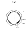
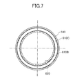
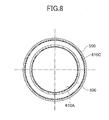
- FIG. 3 to FIG. 9 schematically illustrate example modes of locating the insulating layers 610A-610C in the exhaust gas processing device 100 of the embodiment of the present invention.
- FIG. 3 to FIG. 9 are cross-sectional views schematically illustrating the exhaust gas processing device 100 of the embodiment taken along a direction perpendicular to the longitudinal direction of the exhaust gas processing device 100.
- the insulating layer 610A is formed only at the first part of the inner surface of the first cylindrical metallic member 600 in contact with the first inorganic mat member 500.
- the insulating layer 610B is formed only at the second part of the outer surface of the first cylindrical metallic member 600 in contact with the second inorganic mat member 510. With this structure, the insulating layer 610B can be relatively easily located.
- the insulating layers 610A and 610B are formed at the first part of the inner surface of the first cylindrical metallic member 600 in contact with the first inorganic mat member 500 and the second part of the outer surface of the first cylindrical metallic member 600 in contact with the second inorganic mat member 510.
- the insulating layer 610C is formed only at the third part of the inner surface of the second cylindrical metallic member 590 in contact with the second inorganic mat member 510.
- the insulating layers 610B and 610C are formed at the second part of the outer surface of the first cylindrical metallic member 600 in contact with the second inorganic mat member 510 and the third part of the inner surface of the second cylindrical metallic member 590 in contact with the second inorganic mat member 510.
- the insulating layers 610A and 610C are formed at the first part of the inner surface of the first cylindrical metallic member 600 in contact with the first inorganic mat member 500 and the third part of the inner surface of the second cylindrical metallic member 590 in contact with the second inorganic mat member 510.
- the insulating layers 610A, 610B and 610C are formed at the first part, the second part and the third part, respectively.
- the insulating layer may be formed at least at one of the first, second and third parts.
- insulating layers 610A-610C which may also be designated by a numerical reference 610, is given in reference to the figures. Although the insulating layer 610B formed at the second part is explained next, the explanation is applicable to the insulating layers 610A and 610C formed at the first and third parts in a similar manner.
- the first cylindrical metallic member 600 has an outer surface 602, and the insulating layer 610B is densely formed on the outer surface 602 without generating a through pore in thickness directions of the insulating layer 610B.
- the terminology of "dense" designates a state in which no through pore exists in the thickness direction of the insulating layer 610B.
- the densely formed insulating layer 610B includes an insulating layer having no pores at all, an insulating layer having only closed pores, and an insulating layer having blind pores opened and clogged only on one side in a thickness direction of the insulating layer.
- the through pore, the closed pore, and the blind pore are described in Characterization of Pore Structure of Filter Media (Fluid/Particle Separation Journal vol. 14, No.3, p.227 to 241 ).
- the method of confirming the densely formed insulating layer includes coating of Cu particles on an entire surface of the insulating layer 610B.
- a pair of the electrodes is installed on the surface of the insulating layer 610B and on the inner surface of the cylindrical metallic member 600.
- a voltage of 500 V is applied between the pair of the electrodes to measure a resistance between the surface of the insulating layer 610B and the inner surface of the cylindrical metallic member 600.
- the resistance is measured by a digital ultrahigh resistance / microammeter, type: R8340, manufactured by ADVANTEST CORPORATION.
- FIG. 19 is a scanning electron micrograph of an densely formed insulating layer of the embodiment of the present invention captured by a scanning electron microscope (SEM). Referring to FIG.
- an image of the densely formed insulating layer 610B having the thickness of 20 ⁇ m or more (400 ⁇ m) is magnified by 500 times using a scanning electron microscope (SEM) manufactured by Hitachi High-Technologies Corporation.
- the resistance of this densely formed insulating layer 610B is more than 4.0 ⁇ 10 4 ⁇ .
- a resistance value between the surface of the insulating layer of the thickness of 20 ⁇ m or more in which the through pores exist and the outer surface of the cylindrical metallic member 600 was less than 4.0 ⁇ 10 4 ⁇ .
- the thickness of the insulating layer 610B is in a range of 20 to 400 ⁇ m.
- the thickness of the insulating layer 610B is less than 20 ⁇ m, it becomes difficult to secure the insulation property between the second cylindrical metallic member 590 and the honeycomb structure 200. Meanwhile, if the thickness of the insulating layer 610B exceeds 400 ⁇ m, a crack is easily generated in the insulating layer 610B at times of manufacturing the insulating layer 610B or using the exhaust gas processing device 100. Then, it becomes difficult to secure the insulation property.
- the insulating layer 610B preferably has a glass layer.
- the glass layer may be any layer containing a component of glass such as quartz glass and alkali glass.
- the reason why the glass layer becomes the densely formed insulating layer is that air inside the molten glass is extracted when the glass ingredient is melted in a process of forming the glass layer on the outer surface of the first cylindrical metallic member 600.
- the glass ingredient contained in the glass layer may be barium glass, boron glass, strontium glass, alumina silicate glass, soda-zinc glass, soda-barium glass or the like, and more preferably, silicate glass containing barium.
- the glass ingredient contained in the glass layer may be one or a combination of the above-mentioned glasses.
- the melting point of the glass layer is preferably 400 to 1000°C. If the melting point of the glass layer is less than 400°C, the glass layer easily softened during the exhaust gas processing device is used. Then, an effect of the insulation is lost. On the other hand, if the melting point of the glass layer exceeds 1000°C, a heat treatment at a high temperature becomes necessary at a time of forming the glass layer in the first cylindrical metallic member 600. At this time, the first cylindrical metallic member 600 is degraded.
- the thickness of the glass layer is in a range of 20 to 400 ⁇ m. If the thickness of the glass layer is less than 20 ⁇ m, it becomes difficult to secure the insulation property between the first cylindrical metallic member 600 and the honeycomb structure 200. Meanwhile, if the thickness of the glass layer exceeds 400 ⁇ m, a crack is easily generated in the glass layer at times of manufacturing the glass layer or using the exhaust gas processing device 100. Then, it becomes difficult to secure the insulation property.
- the insulating layer 610B is preferably a mixed layer formed by an amorphous inorganic material (glass ingredient) and a crystalline metal oxide.
- the amorphous inorganic material may be barium glass, boron glass, strontium glass, alumina silicate glass, soda-zinc glass, soda-barium glass or the like.
- the crystalline metal oxide may be at least one of ferric oxide, cobalt oxide, copper oxide, manganese oxide, chrome oxide and aluminum oxide.
- the reason why the mixed layer becomes the densely formed insulating layer is that air inside the amorphous inorganic material (glass ingredient) is extracted when the amorphous inorganic material (glass ingredient) is melted in a process of forming the glass layer on the outer surface 602 of the first cylindrical metallic member 600.
- the thickness of the mixed layer is in a range of 50 to 400 ⁇ m. If the thickness of the mixed layer is less than 50 ⁇ m, it becomes difficult to secure the insulation property between the first cylindrical metallic member 600 and the honeycomb structure 200. Meanwhile, if the thickness of the mixed layer exceeds 400 ⁇ m, a crack is easily generated in the mixed layer at times of manufacturing the mixed layer or using the exhaust gas processing device 100. Then, it becomes difficult to secure the insulation property.
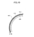
- FIG. 10 is a cross-sectional view of a part of other first cylindrical metallic member 600 included in the exhaust gas processing device 100 of the embodiment of the present invention. Referring to FIG. 10 , other mode of the outer surface 602 of the first cylindrical metallic member 600 is illustrated.
- an insulating layer 610B installed outside the outer surface 602 of the first cylindrical metallic member 600 has a double layer structure.
- the insulating layer 610B includes a first layer 612 and a second layer 614 in an order from the circular center of the first cylindrical metallic member 600 to the outer periphery of the first cylindrical metallic member 600.
- the second layer 614 may be the above-mentioned glass layer.
- the first layer 612 increases adhesion between the outer surface 602 of the first cylindrical metallic member 600 and the second layer 614.
- the first layer 612 may be the above-mentioned mixed layer.
- the first layer 612 preferably has a coefficient of thermal expansion between a coefficient of thermal expansion ⁇ A of the first cylindrical metallic member 600 and a coefficient of thermal expansion ⁇ B of the second cylindrical metallic member 614.
- the coefficient of thermal expansion ⁇ A of the first cylindrical metallic member 600 is about 17 ⁇ 10 -6 /°C.
- the coefficient of thermal expansion ⁇ B of the second cylindrical metallic member 614 is about 0.6 ⁇ 10 -6 /°C.
- the range of the coefficient of thermal expansion ⁇ A of the first cylindrical metallic member 600 is determined to be from 0.6x10 -6 /°C to 17 ⁇ 10 -6 /°C, it is possible to form the insulating layer 610B having good adhesion between the first layer 612 and the first cylindrical metallic member 600 of the exhaust gas processing device 100. This is because stress caused by a difference of thermal expansion between the first cylindrical metallic member 600 and the insulating layer 610B is relaxed.
- the first layer 612 has a thickness of 50 ⁇ m or more
- the second layer 614 has a thickness of 20 ⁇ m or more
- the first layer 612 has a thickness of 50 ⁇ m or more
- the second layer 614 has a thickness of 20 ⁇ m or more. If the thickness of the first layer 612 is less than 50 ⁇ m and the thickness of the second layer 614 is less than 20 ⁇ m or less, it becomes difficult to secure the insulation property between the first cylindrical metallic member 600 and the honeycomb structure 200.
- the thickness of the insulating layer 610B is preferably 400 ⁇ m or less.
- the insulating layer 610B having the double layer structure exceeds 40 ⁇ m, a crack may be generated in the insulating layer 610B having the double layer structure at times of manufacturing the insulating layer 610B or using the exhaust gas processing device 100. Therefore, it becomes difficult to secure the insulation property.
- the insulating layer 610B has the double layer structure.
- the number of the layers forming the insulating layer 610B is not limited to two (double).
- the insulating layer 610B may be a triple layer structure, a quad layer structure or the like.
- the honeycomb structure 200 has a cylindrical shape.
- the shape of the honeycomb structure 200 is not specifically limited.
- the shape of the honeycomb structure 200 may be a cylindroid, a square-pillar, a polygonal pillar or the like.
- the honeycomb structure 200 has a so-called integral structure in which a single honeycomb unit is included.
- the honeycomb structure may have a so-called separable structure in which plural honeycomb units are included.
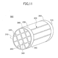
- FIG. 11 is a perspective view schematically illustrating other example honeycomb structure included in the exhaust gas processing device of the embodiment of the present invention.
- FIG. 12 schematically illustrates an example honeycomb unit forming the honeycomb structure 300 illustrated in FIG. 11 .
- the honeycomb structure 300 has the separable structure.
- the honeycomb structure 300 includes two opened end surfaces 310 and 315 and an outer peripheral surface 330.
- the honeycomb structure 300 is formed by connecting plural honeycomb units 340 by interposing adhesive layers 350.
- the honeycomb structure 300 illustrated in FIG. 11 includes four rectangular pillars vertically and horizontally arranged. After vertically and horizontally arranging and joining the four by four (sixteen) rectangular pillars by interposing the adhesive layer 350, the periphery of the outer peripheral surface 330 is processes in a circular shape in a cross-sectional view perpendicular to the longitudinal direction.
- the honeycomb units 340 extend from an end surface 342 to another end surface 343 along a longitudinal direction of the honeycomb units 340.
- the honeycomb units 340 may be made of a material whose main component is, for example, silicon carbide (SiC).
- SiC silicon carbide
- AlN aluminum nitride
- the cell walls 324 of the honeycomb unit 340 include a catalytic agent carrying layer made of ⁇ -alumina.
- the catalytic agent carrying layer carries a noble metal catalytic agent of at least one of platinum and rhodium.
- a pair of electrodes 360 and 361 is located at any portions of the outer peripheral surface 330.
- the electrodes 360 and 361 are located in the vicinity of the end surfaces of the outer peripheral surface 330 in FIG. 11 .
- the honeycomb structure 300 undertakes resistance heating when electricity is applied to both of the electrodes 360 and 361.
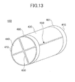
- FIG. 13 illustrates a honeycomb structure 400 having other separable structure.
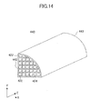
- FIG. 14 schematically illustrates an example honeycomb unit forming the honeycomb structure 400 illustrated in FIG. 13 .
- the honeycomb structure 400 includes two opened end surfaces 410 and 415 and an outer peripheral surface 430.
- the honeycomb structure 400 is formed by connecting plural honeycomb units 440 by interposing adhesive layers 450.
- the honeycomb structure 400 is formed by four honeycomb units 440.
- the four honeycomb units 440 shaped in a fan-like pillar are arranged so that the outer peripheral flat surfaces of the four honeycomb units face each other and joined each other by interposing the adhesive layer 450.
- the above fan-like pillar shape has a cross-sectional view perpendicular to the longitudinal direction of the honeycomb unit defined by only two straight lines having the same lengths and one circular arc connected to the two straight lines.
- the shape and number of the honeycomb units are not limited to the above and any shape and any number can be employed.
- the honeycomb units 440 include plural cells 422 opened at both end surfaces 442 and 443 and cell walls 424 separating the cells 422.
- the honeycomb units 440 may be made of a material whose main component is, for example, silicon carbide (SiC).
- SiC silicon carbide
- AlN aluminum nitride
- the cell walls 424 of the honeycomb unit 440 include a catalytic agent carrying layer made of ⁇ -alumina.
- the catalytic agent carrying layer carries a noble metal catalytic agent of at least one of platinum and rhodium.
- a pair of electrodes 460 and 461 is located at any portions of the outer peripheral surface 430.
- the pair of the electrodes 460 and 461 are located in the vicinity of the end surfaces of the outer peripheral surface 430 in FIG. 13 .
- the honeycomb structure 400 undertakes resistance heating when electricity is applied to the both of the electrodes 460 and 461.
- the honeycomb units 340 and 440 may be made of a material of which main component is, for example, silicon carbide (SiC).
- SiC silicon carbide
- AlN aluminum nitride
- the cross-sectional shape of the honeycomb units 340 and 440 perpendicular to the longitudinal direction of the honeycomb units 340 and 440 are not specifically limited and may be any shape.
- the cross-sectional shapes of the honeycomb units 340 and 440 may be a square, a rectangle, a substantial hexagon or the like.
- the cross-sectional shapes of the cells 322 of the honeycomb unit 340 and the cells 422 of the honeycomb unit 440 perpendicular to the longitudinal direction of the cells 322 and 422 are not specifically limited and may further be a triangle, a polygon or the like.
- the cell density of the honeycomb units 340 and 440 is preferably in a range of 15.5 to 186 pieces / cm 2 (100 to 1200 cpsi), more preferably in a range of 46.5 to 170 pieces / cm 2 (150 to 800 cpsi) and further more preferably in a range of 62 to 155 pieces / cm 2 (150 to 400 cpsi).
- the porosities of the honeycomb units 340 and 440 are 35 to 70%.
- the thicknesses of the cell walls 324 of the honeycomb unit 340 and the thicknesses of the cell walls 424 of the honeycomb unit 440 are not specifically limited. However, a preferable lower limit is 0.1 mm in consideration of the strength, and a preferable upper limit is 0.4 mm in consideration of a conversion capability.
- the catalytic agents carried by the cell walls 324 of the honeycomb unit 340 and the cell walls 424 of the honeycomb unit 440 are not specifically limited and may be platinum, rhodium, palladium or the like.
- the catalytic agents may be carried by the cell walls 324 and 424 interposing alumina layers between the catalytic agents and the cell walls 324 and 424.
- the adhesive layers 350 and 450 of the honeycomb structures 300 and 400 use a paste for the adhesive layer as a raw material in forming the adhesive layers 350 and 450.
- the paste for the adhesive layer may be inorganic particles and an inorganic binder and may include at least one of an inorganic fiber and an organic binder, when necessary.
- the inorganic particles for the paste for the adhesive layer are preferably silicon carbide (SiC).
- the inorganic binder may be inorganic sol, clay binder or the like.
- the inorganic sol may be alumina sol, silica sol, titania sol, water glass or the like.
- the clay binder may be white clay, kaolin (porcelain clay), montmorillonite, sepiolite, attapulgite or the like. These clay binders may be used alone or used in combination.
- the inorganic binder is preferebly alumina sol, silica sol, titania sol, water glass, sepiolite, attapulgite or the like.
- the material of the inorganic fiber is preferably alumina, silica, silicon carbide, silica alumina, glass, potassium titanate, aluminum borate or the like.
- the materials of the inorganic fiber may be used alone or used in combination.
- the material of the inorganic fiber is more preferably silica alumina.
- the organic binder is not specifically limited and may be one or more of polyvinyl alcohol, methyl cellulose, ethyl cellulose, carboxymethyl cellulose and the like.
- the organic binder is preferably carboxymethyl cellulose.
- the thickness of the adhesive layer is preferably in a range of 0.3 to 2 mm. If the thickness of the adhesive layer is less than 0.3 mm, sufficient adhesion strength between the adhesive layer and the honeycomb unit is not obtainable. On the other hand, if the thickness of the adhesive layer exceeds 2 mm, the pressure loss of the honeycomb structures 300 and 400 increases. The number of the joined honeycomb units is appropriately selected in conformity with the size of the honeycomb structures 300 and 400.
- the first and second inorganic mat members 500 and 510 may be a mat material having any composition as long as the inorganic fiber are contained.
- the inorganic mat members 500 and 510 may contain inorganic fibers of an average diameter of 3 to 8 ⁇ m made of alumina and silica.
- the inorganic mat member 500 may contain an organic binder.
- the thicknesses of the first and second inorganic mat members 500 and 510 are preferably in a range of 1 to 20 mm where the first and second inorganic mat members 500 and 510 are accommodated in the first and second cylindrical metallic members 600 and 590.
- the thickness of the first inorganic mat member 500 is less than 1 mm, a buffer effect between the honeycomb structures 200, 300 and 400 and the first cylindrical metallic member 600 becomes insufficient when the honeycomb structures 200, 300 and 400 and the first cylindrical metallic member 600 are actually installed in a vehicle or the like. Thus, it is easy that the honeycomb structures 200, 300 and 400 are broken.
- the thickness of the second inorganic mat member 510 is less than 1 mm, a buffer effect between the first cylindrical metallic member 600 and the second cylindrical metallic member 590 becomes insufficient when the first cylindrical metallic member 600 and the second cylindrical metallic member 590 are actually installed in a vehicle or the like. Thus, it is easy that the first cylindrical metallic member 600 and the second cylindrical metallic member 590 are broken.
- the thickness of the first inorganic mat member 500 is more than 20 mm, a retaining force of the honeycomb structures 200, 300 and 400 decreases when the honeycomb structures 200, 300 and 400 are actually installed in a vehicle. Thus, it is easy that a positional relationship between the honeycomb structures 200, 300 and 400 and the first cylindrical metallic member 600 changes or the honeycomb structures 200, 300 and 400 drop off the first cylindrical metallic member 600. Meanwhile, if the thickness of the second inorganic mat member 510 is more than 20 mm, a retaining force of the first cylindrical metallic member 600 decreases.
- the densities of the first and second inorganic mat members 500 and 510 are preferably in a range of 0.05 to 0.5 g / cm 3 where the first and second inorganic mat members 500 and 510 are accommodated in the first and second cylindrical metallic members 600 and 590. If the density of the first inorganic mat member 500 is less than 0.05 g / cm 3 , a buffer effect between the honeycomb structures 200, 300 and 400 and the first cylindrical metallic member 600 becomes insufficient when the honeycomb structures 200, 300 and 400 and the first cylindrical metallic member 600 are actually installed in a vehicle or the like. Thus, it is easy that the honeycomb structures 200, 300 and 400 are broken.
- the density of the second inorganic mat member 510 is less than 0.05 g / cm 3 , a buffer effect between the first cylindrical metallic member 600 and the second cylindrical metallic member 590 becomes insufficient when the first cylindrical metallic member 600 and the second cylindrical metallic member 590 are actually installed in a vehicle or the like. Thus, it is easy that the first cylindrical metallic member 600 and the second cylindrical metallic member 590 are broken. If the density of the first inorganic mat member 500 is more than 0.5 g / cm 3 , a pressure received by the first inorganic member 500 from the first cylindrical metallic member 600 and the honeycomb structures 200, 300 and 400 becomes great. Thus, it is easy that the first inorganic mat member 500 is crashed or broken.
- the density of the second inorganic mat member 510 is more than 0.5 g/cm 3 , pressures received by the second inorganic member 510 from the first and second cylindrical metallic members 600 and 590 become great. Thus, it is easy that the second inorganic mat member 510 is crashed or broken.
- the exhaust gas processing device 100 of the embodiment of the present invention is manufactured, the first inorganic mat member 500 is wound around the outer peripheral surfaces of the honeycomb structures 200, 300 and 400, and then the honeycomb structures 200, 300 and 400 having the first inorganic mat member 500 are accommodated in the cylindrical metallic member 600.
- the second inorganic mat member 510 is wound around the outer peripheral surface of the first cylindrical metallic member 600, and then the first cylindrical metallic member 600 having the second inorganic mat member 510 is accommodated in the second cylindrical metallic member 590.
- an example manufacturing method of the honeycomb structure and an example forming method of the insulating layer on the cylindrical metallic member are described.
- the honeycomb structure of the present invention is manufactured by the following method.
- a manufacturing method of the honeycomb structures 300 and 400 in the "separable structure" illustrated in FIG. 11 and FIG. 13 is described.
- the manufacturing method of the honeycomb unit is applicable to the manufacture of the honeycomb structure 200 of the integral structure except for adhesion of the plural honeycomb units with the adhesive layers.
- the main component of a raw paste is silicon carbide (SiC).
- SiC silicon carbide
- the raw paste undergoes extrusion molding to manufacture a honeycomb molded body.
- AlN aluminum nitride
- AlN aluminum nitride
- AlN aluminum nitride
- the organic binder is not specifically limited and may be one or a combination of methyl cellulose, carboxymethyl cellulose, hydroxyethyl cellulose, polyethylene glycol, phenol resin, epoxy resin and the like.
- the amount of the organic binder is 1 to 10 parts by weight relative to the inorganic particle, the inorganic binder and the inorganic fiber of 100 parts by weight in total.
- the dispersing medium is not specifically limited and may be water, an organic solvent such as benzene, alcohol such as methanol, and the like.
- the molding auxiliary agent is not specifically limited and may be ethylene glycol, dextrin, fatty acid, fatty acid soap, polyalcohol and the like.
- the raw paste is not specifically limited and preferably mixed and kneaded.
- the raw paste may be kneaded by a mixer or an attritor or sufficiently kneaded by a kneader or the like.
- the method of shaping the raw paste is not specifically limited and is preferably extrusion molding to shape like honeycomb having cells. It is preferable to dry the obtained honeycomb molded body.
- a drying appartus is not specifically limited and may be a microwave drying appartus, a hot air drying appartus, a dielectric drying appartus, a decompression drying appartus, a vacuum drying appartus, a freeze drying appartus and the like. It is preferable to degrease the obtained honeycomb molded body.
- a condition for degreasing the shaped honeycomb is not specifically limited and is appropriately selectable depending on the kind and the amount of the organic substance.
- the condition is preferably about two hours at a degree of 400°C.
- the firing condition is not specifically limited and is preferably fired for a time of 3 hours at a temperature of 2200°C under a inert gas atmosphere such as argon.
- a paste for an adhesive layer is coated on side surfaces of the above fired honeycomb unit so as to have a uniform thickness, other honeycomb units are sequentially laminated interposing the paste for the adhesive layer between the other honeycomb units and the side surfaces of the honeycomb unit.
- the paste for the adhesive layer will be the adhesive layer. This process is repeated to manufacture the honeycomb unit having a predetermined size.
- the honeycomb structure is heated to dry, degrease and solidify the paste for the adhesive layer to form the adhesive layer and simultaneously the honeycomb units are fixed one another.
- the heating temperature of the honeycomb structure is preferably 500 to 800°C, more preferably 600 to 700°C. If the temperature of heating the honeycomb structure is less than 500°C, condensation polymerization of the inorganic binder contained in the paste for the adhesive layer is not processed to lower the adhesion strength of the adhesive layer.
- the honeycomb unit may shift from a predetermined position or drop off the vehicle.
- the temperature of heating the honeycomb unit exceeds 800°C, because the condensation polymerization of the inorganic binder contained in the paste for the adhesive layer is completed, an effect of further enhancing the strength of the honeycomb structure is not obtainable and the productivity becomes bad.
- the time duration for heating the honeycomb structure is preferably about 2 hours.
- a cell wall of the honeycomb unit includes a catalytic agent carrying layer made of ⁇ -alumina.
- the catalytic agent carrying layer carries a noble metal catalytic agent of at least one of platinum and rhodium.
- the electrodes are located on the outer peripheral surface of the honeycomb structure.
- the electrodes may be formed by thermal spraying metal or sputtering metal as described above.
- honeycomb structures 300 and 400 of the separable structure as illustrated in FIG. 11 and FIG. 13 can be manufactured.
- the forming method of the insulating layer on the cylindrical metallic member is described next.
- the forming method of the insulating layer 610B on the outer peripheral surface of the first cylindrical metallic member 600 as illustrated in FIG. 4 is exemplified. This forming method is applicable to a case where an insulating layer is formed on another portion of the exhaust gas processing device.
- the first cylindrical metallic member 600 is prepared.
- the first cylindrical metallic member 600 may be stainless steel (e.g., SUS304 and SUS430) or nickel base alloy.
- the insulating layer 610B is formed on the outer surface 602 of the first cylindrical metallic member 600. As described, the insulating layer 610B may include a glass layer and the insulating layer 610B may include a mixed layer.
- a forming method of the insulating layer 610B is not specifically limited and may be a spray coating method, a brush painting method or the like for providing a glass component.
- the forming method is the same even if the insulating layer has two or more layers.
- Coating and baking of the insulating layer may be repeated by several times to secure the density.
- the formed insulating layer is fired to make the insulating layer be fixed to the outer surface of the first cylindrical metallic member. If the above mentioned glass layer or mixed layer is used as the insulating layer, the calcination temperature after forming the insulating layer is preferably in a range of 400 to 1000°C.
- the material of the insulating layer 610B and the material of the first cylindrical metallic member 600 cannot cause chemical bond at an interface between the insulating layer 610B and the first cylindrical metallic member 600. Therefore, a composite oxide of the materials of the insulating layer 610B and the first cylindrical metallic member 600 cannot be produced to thereby lower the adhesion between the insulating layer 610B and the first cylindrical metallic member 600. In this case, there is a probability that the insulating layer 610B peels off the first cylindrical metallic member 600.
- the exhaust gas processing device 100 in FIG. 1 is exemplified as the example exhaust gas processing device of the embodiment.
- the embodiment is applicable to exhaust gas processing devices having other structures. Next, other structure of the exhaust gas processing device of the embodiment is described.
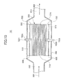
- FIG. 15 , FIG. 16 and FIG. 17 illustrate other structures of the exhaust gas processing device of the embodiment.
- the exhaust gas processing devices 101, 102 and 103 have a structure similar to that of the exhaust gas processing device 100 illustrated in FIG. 1 .
- the same reference symbols as those in FIG. 1 are attached to FIG. 15 , FIG. 16 and FIG. 17 .
- the positions of electric terminals 7521 and 7522 are different from the positions of the electric terminals 7501 and 7502 illustrated in FIG. 1 .
- the two electric terminals 7521 and 7522 are positioned at a center portion of the honeycomb structure 200 and not at both ends of the honeycomb structure 200.
- the electric terminals 7521 and 7522 extend in opposite directions perpendicular to the longitudinal direction of the honeycomb structure 200.
- the two electrodes of the honeycomb structure 200 are arranged in the vicinity of a center portion of the outer peripheral surface of the honeycomb structure 200 not like the end portions illustrated in FIG. 2 and FIG. 11 .
- two electric terminals 7521 and 7522 are not in contact with the first and second mat member 500 and 510.
- insulation among the two electric terminals 7521 and 7522, the first and second cylindrical metallic members 600 and 590, and the first and second mat members 500 and 510 are secured.
- the positions of the first and second mat members 500 and 510 are different from the positions of the first and second mat members 500 and 510 illustrated in FIG. 17 .
- the positions where the first and second inorganic mat members are located are not limited.
- Various structures are applicable to the exhaust gas processing device of the embodiment.
- a cylindrical metallic member having the insulating layer is manufactured. Further, an exhaust gas processing device including the cylindrical metallic member is manufactured.
- the cylindrical metallic member was made of a steel pipe of SUS304 having an outer diameter of 105 mm, a wall thickness of 2 mm and a total length of 90 mm. Before the use, the steel pipe of SUS304 undergoes ultrasonic cleaning in alcohol.
- the outer surface of the steel pipe of SUS304 undergoes sandblasting.
- sandblasting alumina abrasive grain of an abrasive number #80 was used and a treatment time was 10 minutes.
- the maximum height Rz of the outer surface of the steel pipe of SUS304 is 2.5 ⁇ m after sandblasting the steel pipe.
- the insulating layer was formed on the outer surface of the steel pipe of SUS304.
- water of 100 parts by weight is added to silicate glass powder containing barium of 100 parts by weight.
- the water and silicate glass powder underwent wet blending using a ball mill to thereby prepare slurry.
- This slurry was sprayed to coat the outer surface of the steel pipe of SUS304 and dried for 2 hours at a room temperature of 25°C.
- the steel pipe of SUS304 was heated at 900°C for 20 minutes to thereby form a glass layer on the outer surface of the steel pipe of SUS304.
- the thickness of the glass layer was 30 ⁇ m.
- the steel pipe of SUS304 is referred to as "a cylindrical metallic member of Example 1".
- the exhaust gas processing device was manufactured as follows.
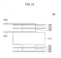
- FIG. 18 schematically illustrates an exhaust gas processing device of according to Examples and Comparative Examples of the present invention.
- the exhaust gas processing device 900 includes a honeycomb structure 910, a first inorganic mat member 920, a cylindrical metallic member 930, a second inorganic mat member 950, a second cylindrical metallic member 960 and a pair of probe electrodes 940A and 940B for measurement.
- the honeycomb structure 910 was a cylindrical honeycomb structure having an inner diameter of 93 mm and a total length of 100 mm as illustrated in FIG. 11 .
- the honeycomb units forming the honeycomb structure 910 were made of silicon carbide.
- the probe electrode for measurement 940A made of aluminum was attached to a side surface of the honeycomb structure 910.
- the probe electrode for measurement 940A has dimensions of a total length of 100 mm, a width of 10 mm and a thickness of 0.3 mm.
- the probe electrode for measurement 940A was fixed to the side surface of the honeycomb structure 910 using a commercially available insulating tape.
- the inorganic mat member 920 was wound around the side surface of the honeycomb structure 910.
- the first inorganic mat member 920 was made of alumina fiber.
- the width of the first inorganic mat member 920 in the width direction of FIG. 18 was 30 mm.
- the honeycomb structure around which the first inorganic member was wound was press-fit into the cylindrical metallic member 930 of Example 1.
- the thickness of the first inorganic mat member 920 accommodated in the cylindrical metallic member 920 was 4 mm.
- the second inorganic mat member 950 was wound around the side surface of the cylindrical metallic member 930 of Example 1.
- the second inorganic mat member 950 was made of alumina fiber.
- the width of the second inorganic mat member 950 in the width direction of FIG. 18 was 30 mm.
- the second cylindrical metallic member 960 was made of a steel pipe of SUS304 having an outer diameter of 135 mm, a wall thickness of 2 mm and a total length of 90 mm.
- the thickness of the second inorganic mat member 960 accommodated in the second cylindrical metallic member 950 was 13 mm.
- Another probe electrode for measurement 940B made of aluminum is located on the outer surface of the second cylindrical metallic member 960.
- the probe electrode for measurement 940B has dimensions of a total length of 100 mm, a width of 10 mm and a thickness of 0.3 mm.
- the probe electrode for measurement 940B is fixed to the outer surface of the second cylindrical metallic member 960 by a commercially available insulating tape.
- the exhaust gas processing device 900 obtained as above is referred to as "an exhaust gas processing device of Example 1".
- Example 2 In a similar manner to Example 1, a cylindrical metallic member of Example 2 and an exhaust gas processing device of Example 2 were manufactured. However, in Example 2, the thickness of a glass layer formed on the outer surface of the cylindrical metallic member of Example 2 is 20 ⁇ m. The other conditions are similar to those in Example 1.
- Example 3 In a similar manner to Example 1, a cylindrical metallic member of Example 3 and an exhaust gas processing device of Example 3 were manufactured. However, in Example 3, the thickness of a glass layer formed on the outer surface of the cylindrical metallic member of Example 3 was 80 ⁇ m. The other conditions are similar to those in Example 1.
- Example 4 In a similar manner to Example 1, a cylindrical metallic member of Example 4 and an exhaust gas processing device of Example 4 were manufactured. However, in Example 4, the thickness of a glass layer formed on the outer surface of the cylindrical metallic member of Example 4 was 400 ⁇ m. The other conditions are similar to those in Example 1.
- Example 1 In a similar manner to Example 1, a cylindrical metallic member of Comparative Example 1 and an exhaust gas processing device of Comparative Example 1 were manufactured. However, in Comparative Example 1, the thickness of a glass layer formed on the outer surface of the cylindrical metallic member of Comparative Example 1 was 8 ⁇ m. The other conditions are similar to those in Example 1.
- Example 2 In a similar manner to Example 1, a cylindrical metallic member of Comparative Example 2 and an exhaust gas processing device of Comparative Example 2 were manufactured. However, in Comparative Example 2, the thickness of a glass layer formed on the outer surface of the cylindrical metallic member of Comparative Example 2 was 600 ⁇ m. The other conditions are similar to those in Example 1.
- Example 5 In a similar manner to Example 1, a cylindrical metallic member of Example 5 and an exhaust gas processing device of Example 5 were manufactured. However, in Example 5, an insulating layer is formed on the outer surface of an inner steel pipe of SUS304 (hereinafter, referred to as an inner pipe) as follows.
- Manganese oxide powder (MnO 2 ), ferric oxide powder (FeO), copper oxide (CuO), and silicate glass powder containing barium underwent dry blending in a weight ratio of MnO 2 :FeO:CuO:silicate glass powder of 30:5:5:60 to obtain mixed powder. Water of 100 parts by weight is added to the mixed powder of 100 parts by weight. Then the water and mixed powder underwent wet blending to thereby prepare slurry.
- This slurry was sprayed to coat the outer surface of the inner steel pipe of SUS304 and dried for 2 hours at a room temperature of 25°C. Thereafter, the inner steel pipe was heated at 900°C for 20 minutes to form a mixed layer of the crystalline metal oxide and the amorphous binder.
- the thickness of the mixed layer is 50 ⁇ m.
- the inner steel pipe is referred to as a cylindrical metallic member of Example 5.
- Example 5 An exhaust gas processing device of Example 5 was manufactured in a similar manner to Example 1 using the cylindrical metallic member of Example 5.
- Example 6 In a similar manner to Example 5, a cylindrical metallic member of Example 6 and an exhaust gas processing device of Example 6 were manufactured. However, in Example 6, the thickness of a glass layer formed on the outer surface of the cylindrical metallic member of Example 6 was 100 ⁇ m. The other conditions are similar to those in Example 5.
- Example 7 In a similar manner to Example 5, a cylindrical metallic member of Example 7 and an exhaust gas processing device of Example 7 were manufactured. However, in Example 7, the thickness of a glass layer formed on the outer surface of the cylindrical metallic member of Example 7 was 400 ⁇ m. The other conditions are similar to those in Example 5.
- Example 8 In a similar manner to Example 1, a cylindrical metallic member of Example 8 and an exhaust gas processing device of Example 8 were manufactured. However, in Example 8, an insulating layer is formed on an outer surface of an inner pipe.
- Aluminum oxide powder (Al 2 O 3 ) and silicate glass powder containing barium underwent dry blending in a weight ratio of Al 2 O 3 : silicate glass powder of 10: 90 to obtain mixed powder. Water of 100 parts by weight is added to the mixed powder of 100 parts by weight. Then, the water and mixed powder underwent wet blending to thereby prepare slurry.
- This slurry was sprayed to coat the outer surface of the inner pipe and dried for 2 hours at a room temperature of 25°C. Thereafter, the inner pipe was heated at 900°C for 20 minutes to form a mixed layer of the crystalline metal oxide and the amorphous binder. The thickness of the mixed layer was 100 ⁇ m.
- the inner steel pipe is referred to as a cylindrical metallic member of Example 8.
- An exhaust gas processing device of Example 8 is manufactured in a similar manner to Example 1 using the cylindrical metallic member of Example 8.
- Example 9 In a similar manner to Example 1, a cylindrical metallic member of Example 9 and an exhaust gas processing device of Example 9 were manufactured. However, in Example 9, an insulating layer is formed on an outer surface of an inner pipe.
- Manganese oxide powder (MnO 2 ) and silicate glass powder containing barium underwent dry blending in a weight ratio of MnO 2 :silicate glass powder of 15:85 to obtain mixed powder. Water of 100 parts by weight is added to the mixed powder of 100 parts by weight. Then, the water and mixed powder underwent wet blending to thereby prepare slurry.
- This slurry was sprayed to coat the outer surface of the inner pipe and dried for 2 hours at a room temperature of 25°C. Thereafter, the inner pipe was heated at 940°C for 20 minutes to form a mixed layer of the crystalline metal oxide and the amorphous binder. The thickness of the mixed layer was 100 ⁇ m.
- the inner pipe is referred to as a cylindrical metallic member of Example 9.
- Example 9 An exhaust gas processing device of Example 9 was manufactured in a similar manner to Example 1 using the cylindrical metallic member of Example 9.
- Example 5 In a similar manner to Example 5, a cylindrical metallic member of Comparative Example 3 and an exhaust gas processing device of Comparative Example 3 were manufactured. However, in Comparative Example 3, the thickness of the mixed layer formed on the outer surface of the cylindrical metallic member of Comparative Example 3 was 600 ⁇ m. The other conditions are similar to those in Example 5.
- Example 5 In a similar manner to Example 5, a cylindrical metallic member of Comparative Example 4 and an exhaust gas processing device of Comparative Example 4 were manufactured. However, in Comparative Example 4, the thickness of the mixed layer formed on the outer surface of the cylindrical metallic member of Comparative Example 4 was 20 ⁇ m. The other conditions are similar to those in Example 5.
- Example 10 In a similar manner to Example 1, a cylindrical metallic member of Example 10 and an exhaust gas processing device of Example 10 were manufactured. However, in Example 10, an insulating layer is formed on an outer surface of an inner pipe.
- Manganese oxide powder (MnO 2 ), ferric oxide powder (FeO), copper oxide (CuO), and silicate glass powder containing barium underwent dry blending in a weight ratio of MnO 2 :FeO:CuO:silicate glass powder of 30:5:5:60 to obtain mixed powder. Water of 100 parts by weight is added to the mixed powder of 100 parts by weight. Then, the water and mixed powder underwent wet blending using a ball mill to thereby prepare first slurry.
- This first slurry was sprayed to coat the outer surface of the inner pipe and dried for 2 hours at a room temperature of 25°C. Thereafter, the inner pipe was heated at 900°C for 20 minutes to form a mixed layer of the crystalline metal oxide and the amorphous binder on the outer surface of the inner pipe.
- the thickness of the mixed layer was 5 ⁇ m.
- This second slurry was sprayed to coat the mixed layer formed on the outer surface of the inner pipe and dried for 2 hours at a room temperature of 25°C.
- the inner pipe was heated at a temperature of 900°C for 20 minutes to thereby form a glass layer on the mixed layer of the inner pipe.
- the thickness of the glass layer was 20 ⁇ m.
- the inner pipe is referred to as a cylindrical metallic member of Example 10.
- Example 10 An exhaust gas processing device of Example 10 was manufactured in a similar manner to Example 1 using the cylindrical metallic member of Example 10.
- Example 11 In a similar manner to Example 10, a cylindrical metallic member of Example 11 and an exhaust gas processing device of Example 11 were manufactured. However, in Example 11, the thickness of the mixed layer formed on the outer surface of the cylindrical metallic member of Example 11 was 200 ⁇ m. The other conditions are similar to those in Example 10.
- Example 12 In a similar manner to Example 10, a cylindrical metallic member of Example 12 and an exhaust gas processing device of Example 12 were manufactured. However, in Example 12, the thickness of the mixed layer formed on the outer surface of the cylindrical metallic member of Example 12 was 50 ⁇ m, and the thickness of the glass layer was 25 ⁇ m. The other conditions are similar to those in Example 10.
- Example 13 In a similar manner to Example 10, a cylindrical metallic member of Example 13 and an exhaust gas processing device of Example 13 were manufactured.
- the first slurry is prepared as follows.
- Aluminum oxide powder (Al 2 O 3 ) and silicate glass powder containing barium underwent dry blending in a weight ratio of Al 2 O 3 :silicate glass powder of 10: 90 to obtain mixed powder.
- Water of 100 parts by weight is added to the mixed powder of 100 parts by weight .
- the water and mixed powder underwent wet blending using a ball mill to thereby prepare first slurry.
- Example 10 The other conditions are similar to those in Example 10 except for the use of this first slurry.
- Example 14 the thickness of the mixed layer formed on the outer surface of the cylindrical metallic member of Example 14 was 50 ⁇ m, and the thickness of the glass layer was 25 ⁇ m.
- Example 14 In a similar manner to Example 10, a cylindrical metallic member of Example 14 and an exhaust gas processing device of Example 14 were manufactured. With Example 14, first slurry was prepared as follows.
- Manganese oxide powder (MnO 2 ) and silicate glass powder containing barium underwent dry blending in a weight ratio of MnO 2 :silicate glass powder of 15: 85 to obtain mixed powder. Water of 100 parts by weight is added to the mixed powder of 100 parts by weight. Then, the water and mixed powder underwent wet blending using a ball mill to thereby prepare the first slurry.
- Example 10 The other conditions are similar to those in Example 10 except for the use of this first slurry.
- the thickness of the mixed layer formed on the outer surface of the cylindrical metallic member of Example 14 was 50 ⁇ m, and the thickness of the glass layer was 25 ⁇ m.
- Example 10 In a similar manner to Example 10, a cylindrical metallic member of Comparative Example 5 and an exhaust gas processing device of Comparative Example 5 were manufactured.
- the thickness of the mixed layer formed on the outer surface of the cylindrical metallic member of Comparative Example 5 was 300 ⁇ m, and the thickness of the glass layer was 300 ⁇ m.
- the other conditions are similar to those in Example 10.
- Example 10 In a similar manner to Example 10, a cylindrical metallic member of Comparative Example 6 and an exhaust gas processing device of Comparative Example 6 were manufactured.
- the thickness of the mixed layer formed on the outer surface of the cylindrical metallic member of Example 6 was 5 ⁇ m, and the thickness of the glass layer was 20 ⁇ m.
- the other conditions are similar to those in Example 10.
- Example 10 In a similar manner to Example 10, a cylindrical metallic member of Comparative Example 7 and an exhaust gas processing device of Comparative Example 7 were manufactured.
- the thickness of the mixed layer formed on the outer surface of the cylindrical metallic member of Comparative Example 7 was 10 ⁇ m, and the thickness of the glass layer was 10 ⁇ m.
- the other conditions are similar to those in Example 10.
- a cylindrical metallic member having the insulating layer is manufactured. Further, an exhaust gas processing device including the cylindrical metallic member is manufactured.
- the cylindrical metallic member is made of a steel pipe of SUS304 having an outer diameter of 105 mm, a wall thickness of 2 mm and a total length of 90 mm. Before using the steel pipe of SUS304, the steel pipe of SUS304 underwent ultrasonic cleaning in alcohol.
- the inner surface of the steel pipe of SUS304 underwent sandblasting.
- sandblasting alumina abrasive grain of an abrasive number #80 was used and a treatment time was 10 minutes.
- the maximum height Rz of the inner surface of the steel pipe of SUS304 is 2.5 ⁇ m after sandblasting the steel pipe.
- the insulating layer was formed on the inner surface of the steel pipe of SUS304.
- water of 100 parts by weight is added to silicate glass powder containing barium of 100 parts by weight.
- the water and silicate glass powder underwent wet blending using a ball mill to thereby prepare slurry.
- the slurry was sprayed to coat the inner surface of the steel pipe of SUS304 and dried for 2 hours at a room temperature of 25°C.
- the steel pipe of SUS304 was heated at 900°C for 20 minutes to thereby form a glass layer on the inner surface of the steel pipe of SUS304.
- the thickness of the glass layer was 80 ⁇ m.
- the steel pipe of SUS304 is referred to as "a cylindrical metallic member of Example 15".
- Example 15 An exhaust gas processing device of Example 15 was manufactured in a similar manner to Example 1 except for the use of the cylindrical metallic member of Example 15 as the inner pipe.
- a cylindrical metallic member having an insulating layer is manufactured. Further, an exhaust gas processing device including the cylindrical metallic member is manufactured.
- the cylindrical metallic member is made of a steel pipe of SUS304 having an outer diameter of 105 mm, a wall thickness of 2 mm and a total length of 90 mm. Before using the steel pipe of SUS304, the steel pipe of SUS304 underwent ultrasonic cleaning in alcohol.
- the inner surface of the steel pipe of SUS304 underwent sandblasting.
- sandblasting alumina abrasive grain of an abrasive number #80 was used and a treatment time was 10 minutes.
- the maximum height Rz of the inner surface of the steel pipe of SUS304 is 2.5 ⁇ m after sandblasting the steel pipe.
- the insulating layer was formed on the inner surface of the steel pipe of SUS304.
- Manganese oxide powder (MnO 2 ), ferric oxide powder (FeO), copper oxide (CuO), and silicate glass powder containing barium underwent dry blending in a weight ratio of MnO 2 :FeO:CuO:silicate glass powder of 30:5:5:60 to obtain mixed powder. Water of 100 parts by weight is added to the mixed powder of 100 parts by weight . Then, the water and mixed powder underwent wet blending to thereby prepare slurry.
- This slurry was sprayed to coat the inner surface of the steel pipe of SUS304 and dried for 2 hours at a room temperature of 25°C.
- the steel pipe of SUS304 was heated at 900°C for 20 minutes to thereby form a mixed layer of crystalline metal oxide and amorphous binder on the inner surface of the steel pipe of SUS304.
- the thickness of the mixed layer was 100 ⁇ m.
- the steel pipe of SUS304 is referred to as "a cylindrical metallic member of Example 16".
- Example 16 An exhaust gas processing device of Example 16 was manufactured in a similar manner to Example 1 except for the use of the cylindrical metallic member of Example 16 as the inner pipe.
- a cylindrical metallic member having an insulating layer is manufactured. Further, an exhaust gas processing device including the cylindrical metallic member is manufactured.
- the cylindrical metallic member is made of a steel pipe of SUS304 having an outer diameter of 105 mm, a wall thickness of 2 mm and a total length of 90 mm. Before using the steel pipe of SUS304, the steel pipe of SUS304 underwent ultrasonic cleaning in alcohol.
- the inner surface of the steel pipe of SUS304 underwent sandblasting.
- sandblasting alumina abrasive grain of an abrasive number #80 was used and a treatment time was 10 minutes.
- the maximum height Rz of the inner surface of the steel pipe of SUS304 is 2.5 ⁇ m after sandblasting the steel pipe.
- the insulating layer was formed on the inner surface of the steel pipe of SUS304.
- Manganese oxide powder (MnO 2 ), ferric oxide powder (FeO), copper oxide (CuO), and silicate glass powder containing barium underwent dry blending in a weight ratio of MnO 2 :FeO:CuO:silicate glass powder of 30:5:5:60 to obtain mixed powder. Water of 100 parts by weight is added to the mixed powder of 100 parts by weight. Then, the water and mixed powder underwent wet blending using a ball mill to thereby prepare first slurry.
- This first slurry was sprayed to coat the inner surface of the steel pipe of SUS304 and dried for 2 hours at a room temperature of 25°C.
- the steel pipe of SUS304 was heated at 900°C for 20 minutes to thereby form a mixed layer of crystalline metal oxide and amorphous binder on the inner surface of the steel pipe of SUS304.
- the thickness of the mixed layer was 5 ⁇ m.
- This second slurry was sprayed to coat the mixed layer formed on the inner surface of the steel pipe of SUS304 and dried for 2 hours at a room temperature of 25°C. Thereafter, the steel pipe of SUS304 was heated at 900°C for 20 minutes to thereby form the mixed layer on the inner surface of the steel pipe of SUS304.
- the thickness of the glass layer was 20 ⁇ m.
- the steel pipe of SUS304 is referred to as "a cylindrical metallic member of Example 17".
- Example 17 An exhaust gas processing device of Example 17 was manufactured in a similar manner to Example 1 except for the use of the cylindrical metallic member of Example 17 as the inner pipe.
- a cylindrical metallic member having an insulating layer is manufactured. Further, an exhaust gas processing device including the cylindrical metallic member was manufactured.
- the cylindrical metallic member is made of a steel pipe of SUS304 having an outer diameter of 135 mm, a wall thickness of 2 mm and a total length of 90 mm. Before using the steel pipe of SUS304, the steel pipe of SUS304 underwent ultrasonic cleaning in alcohol.
- the inner surface of the steel pipe of SUS304 underwent sandblasting.
- sandblasting alumina abrasive grain of an abrasive number #80 was used and a treatment time was 10 minutes.
- the maximum height Rz of the inner surface of the steel pipe of SUS304 is 2.5 ⁇ m after sandblasting the steel pipe.
- Example 18 The steel pipe of SUS304 is referred to as "a cylindrical metallic member of Example 18".
- the exhaust gas processing device having the structure illustrated in FIG. 18 was manufactured as follows.
- the honeycomb structure 910 was a cylindrical honeycomb structure having an inner diameter of 93 mm and a total length of 100 mm as illustrated in FIG. 11 .
- the honeycomb units forming the honeycomb structure 910 were made of silicon carbide.
- a probe electrode for measurement 940A made of aluminum was attached to a side surface of the honeycomb structure 910.
- the probe electrode for measurement 940A has dimensions of a total length of 100 mm, a width of 10 mm and a thickness of 0.3 mm.
- the probe electrode for measurement 940A was fixed to the side surface of the honeycomb structure 910 using a commercially available insulating tape.
- the first inorganic mat member 920 was wound around the side surface of the honeycomb structure 910.
- the first inorganic mat member 920 is made of alumina fiber.
- the width of the first inorganic mat member 920 in the width direction of FIG. 18 is 30 mm.
- the honeycomb structure around which the first inorganic member 920 was wound was press-fit into the first cylindrical metallic member 930.
- the thickness of the first inorganic mat member 920 accommodated in the first cylindrical metallic member 930 was 4 mm.
- the first cylindrical metallic member 930 was made of a steel pipe of SUS304 having an outer diameter of 105 mm, a wall thickness of 2 mm and a total length of 90 mm.
- the second inorganic mat member 950 was wound around the side surface of the first cylindrical metallic member 930.
- the second inorganic mat member 950 was made of alumina fiber.
- the width of the second inorganic mat member 950 in the width direction of FIG. 18 was 30 mm.
- Another probe electrode for measurement 940B made of aluminum was located on the outer surface of the second cylindrical metallic member 960.
- the probe electrode for measurement 940B has dimensions of a total length of 100 mm, a width of 10 mm and a thickness of 0.3 mm.
- the probe electrode for measurement 940B was fixed to the outer surface of the cylindrical metallic member 960 of Example 18 by a commercially available insulating tape.
- the exhaust gas processing device 900 obtained as above is referred to as "an exhaust gas processing device of Example 18".
- a cylindrical metallic member having an insulating layer was manufactured. Further, an exhaust gas processing device including the cylindrical metallic member was manufactured.
- the cylindrical metallic member is made of a steel pipe of SUS304 having an outer diameter of 135 mm, a wall thickness of 2 mm and a total length of 90 mm. Before using the steel pipe of SUS304, the steel pipe of SUS304 underwent ultrasonic cleaning in alcohol.
- the inner surface of the steel pipe of SUS304 underwent sandblasting.
- sandblasting alumina abrasive grain of an abrasive number #80 was used and a treatment time was 10 minutes.
- the maximum height Rz of the inner surface of the steel pipe of SUS304 is 2.5 ⁇ m after sandblasting the steel pipe.
- the insulating layer was formed on the inner surface of the steel pipe of SUS304.
- Manganese oxide powder (MnO 2 ), ferric oxide powder (FeO), copper oxide (CuO), and silicate glass powder containing barium underwent dry blending in a weight ratio of MnO 2 :FeO:CuO:silicate glass powder of 30:5:5:60 to obtain mixed powder. Water of 100 parts by weight is added to the mixed powder of 100 parts by weight. Then, the water and mixed powder underwent wet blending to thereby prepare slurry.
- This slurry was sprayed to coat the inner surface of the steel pipe of SUS304 and dried for 2 hours at a room temperature of 25°C.
- the steel pipe of SUS304 was heated at 900°C for 20 minutes to thereby form a mixed layer of crystalline metal oxide and amorphous binder on the inner surface of the steel pipe of SUS304.
- the thickness of the mixed layer was 100 ⁇ m.
- the steel pipe of SUS304 is referred to as "a cylindrical metallic member of Example 19".
- An exhaust gas processing device of Example 29 was manufactured in a similar manner to Example 1 except for a use of the cylindrical metallic member of Example 19 as an outer steel pipe of SUS304 (hereinafter, referred to as an outer pipe).
- a cylindrical metallic member having an insulating layer was manufactured. Further, an exhaust gas processing device including the cylindrical metallic member was manufactured.
- the cylindrical metallic member is made of a steel pipe of SUS304 having an outer diameter of 135 mm, a wall thickness of 2 mm and a total length of 90 mm. Before using the steel pipe of SUS304, the steel pipe of SUS304 underwent ultrasonic cleaning in alcohol.
- the inner surface of the steel pipe of SUS304 underwent sandblasting.
- sandblasting alumina abrasive grain of an abrasive number #80 was used and a treatment time was 10 minutes.
- the maximum height Rz of the inner surface of the steel pipe of SUS304 is 2.5 ⁇ m after sandblasting the steel pipe.
- the insulating layer was formed on the inner surface of the steel pipe of SUS304.
- Manganese oxide powder (MnO 2 ), ferric oxide powder (FeO), copper oxide (CuO), and silicate glass powder containing barium underwent dry blending in a weight ratio of MnO 2 :FeO:CuO:silicate glass powder of 30:5:5:60 to obtain mixed powder. Water of 100 parts by weight is added to the mixed powder of 100 parts by weight. Then, the water and mixed powder underwent wet blending using a ball mill to thereby prepare first slurry.
- This first slurry was sprayed to coat the inner surface of the steel pipe of SUS304 and dried for 2 hours at a room temperature of 25°C. Thereafter, the steel pipe of SUS304 was heated at 900°C for 20 minutes to thereby form a mixed layer of crystalline metal oxide and amorphous binder on the inner surface of the steel pipe of SUS304.
- the thickness of the mixed layer was 5 ⁇ m.
- This second slurry was sprayed to coat the mixed layer formed on the inner surface of the steel pipe of SUS304 and dried for 2 hours at a room temperature of 25°C. Thereafter, the steel pipe of SUS304 was heated at 900°C for 20 minutes to thereby form a glass layer on the mixed layer of the steel pipe of SUS304.
- the thickness of the glass layer was 20 ⁇ m.
- the steel pipe of SUS304 is referred to as "a cylindrical metallic member of Example 20".
- Example 20 An exhaust gas processing device of Example 20 was manufactured in a similar manner to Example 18 except for the use of the cylindrical metallic member of Example 20.
- Tables 1, 2 and 3 illustrate the compositions, layer thicknesses and locations of the insulating layers of the cylindrical metallic members of Examples 1-20 and Comparative Examples 1-7.
- Table 1 INSULATING LAYER EVALUATION RESULT STRUCTURE COMPOSITION (wt%) THICKNESS OF FIRST LAYER ( ⁇ m) THICKNESS OF SECOND LAYER ( ⁇ m) LOCATION ADHESION MEASURED - RESISTANCE ( ⁇ )
- EXAMPLE 1 GLASSS LAYER (SINGLE LAYER) SILICATE GLASS CONTAINING BARIUM 30 - OUTER SURFACE OF FIRST CYLINDRICAL METALLIC MEMBER GOOD 5.0 ⁇ 10 6
- EXAMPLE 2 GLASS LAYER (SINGLE LAYER) SILICATE GLASS CONTAINING BARIUM 20 - OUTER SURFACE OF FIRST CYLINDRICAL METALLIC MEMBER GOOD 3.0 ⁇ 10 8 EXAMPLE 3 GLASS
- MIXED LAYER FIRST LAYER MnO 2 AMORPHOUS (FIRST LAYER) BINDER(15 : 85) +GLASS LAYER SECOND LAYER SILICATE GLASS (SECOND LAYER) CONTAINING BARIUM 50 25 OUTER SURFACE OF FIRST CYLINDRI CAL METALLIC MEMBER GOOD 5.0 ⁇ 10 8 COMPARATIVE EXAMPLE 5 MIXED LAYER FIRST LAYER MnO 2 : FeO : CuO : (FIRST LAYER) AMORPHOUS BINDER 2.
- Evaluation test of adhesion of the insulating layers was carried out using the cylindrical metallic members of Examples 1-20 and Comparative Examples 1-7.
- the evaluation test of adhesion was a heat shock test.
- the cylindrical metallic members of Examples 1-20 and Comparative Examples 1-7 were heated to be 850°C.
- the cylindrical metallic members which were heated were thrown into water having a temperature of 25°C. Thereafter, the cylindrical metallic members are retrieved to visually observe peel-off of the insulating layers.
- the evaluation results of adhesion are indicated in the column of "ADHESION" of Tables 1 to 3. With the evaluation results of adhesion, the cylindrical metallic members of Examples 1-20 have good adhesion and do not cause peel-off. On the other hand, in the cylindrical metallic members of Comparative Examples 2, 3 and 5, the peel-off is caused after the evaluation test.
- the exhaust gas processing devices of Examples 1-20 and Comparative Examples 1-7 are used to measure values of resistance (volume resistance) of the exhaust gas processing devices.
- the resistance is measured by a resistance measurement instrument (a digital ultrahigh resistance / microammeter, type: R8340, manufactured by ADVANTEST CORPORATION). Specifically, the measurement is carried out as follows.
- distilled water having an electric resistivity of 0.1 to 1.0 M ⁇ cm at a temperature of 25°C was poured into the first and second inorganic mat members 920 and 950 of the exhaust gas processing device 900.
- the electric resistivity was measured by an electric resistivity measuring instrument of model 7727-A100 manufactured by TECHNO-MORIOKA.
- the inorganic mat members 920 and 950 were sufficiently impregnated with water and soaked through.
- the electric resistivity measuring instrument is connected between a pair of probe electrodes for measurement 940A and 940B of the exhaust gas processing device.
- a voltage of 500 V is applied between the probe electrodes 940A and 940B and a resistance value between the probe electrodes 940A and 940B is measured.
- the resistance value in the insulating layer is not measured and the resistance value between the inorganic mat member 920 and 950 impregnated with water and the second cylindrical metallic member 960 is measured.
- the resistance values of the inorganic mat members 920 and 950 impregnated with the distilled water and the second cylindrical metallic member 960 are extremely low (e.g., 1/10 18 to 1/10 6 times) in comparison with the resistance value of the insulating layer. Therefore, the resistance values of the inorganic mat members 920 and 950 impregnated with the distilled water and the second cylindrical metallic member 960 do not substantially affect the resistance value of the insulating layer.
- the resistance value between the inorganic mat member 920 and 950 impregnated with water and the second cylindrical metallic member 960 is measured, the resistance value of the insulating layer is substantially obtainable.
- the measurement results of the resistance values of Examples 1-20 and Comparative Examples 1-7 are listed in the column of "MEASURED RESISTANCE" of Tables 1-3.
- the measured resistances of Comparative Example 1, Comparative Example 4, Comparative Example 6 and Comparative Example 7 are 4.0 ⁇ 10 4 ⁇ or less.
- the measured resistances of Examples 1 to 20 are more than 9.0 ⁇ 10 5 ⁇ or more.
- the resistance values of the exhaust gas processing devices of Examples 1 to 20 are larger than the resistance values of the exhaust gas processing devices of Comparative Examples 1, 4, 6 and 7 by at least 22 times or more. Thus, the good insulation properties are obtained.
- the good insulation properties between the honeycomb structure and the second cylindrical metallic member are secured, and the exhaust gas processing device having excellent adhesion of the insulating layer is obtainable.
- the exhaust gas processing device which can prevent an electric current from leaking into components other than the honeycomb structure.
Landscapes
- Chemical & Material Sciences (AREA)
- Engineering & Computer Science (AREA)
- Chemical Kinetics & Catalysis (AREA)
- Health & Medical Sciences (AREA)
- Toxicology (AREA)
- Combustion & Propulsion (AREA)
- Mechanical Engineering (AREA)
- General Engineering & Computer Science (AREA)
- Exhaust Gas Treatment By Means Of Catalyst (AREA)
- Exhaust Gas After Treatment (AREA)
Applications Claiming Priority (1)
| Application Number | Priority Date | Filing Date | Title |
|---|---|---|---|
| PCT/JP2011/050095 WO2012093481A1 (ja) | 2011-01-06 | 2011-01-06 | 排ガス処理装置 |
Publications (2)
| Publication Number | Publication Date |
|---|---|
| EP2474718A1 true EP2474718A1 (de) | 2012-07-11 |
| EP2474718B1 EP2474718B1 (de) | 2014-06-11 |
Family
ID=44759460
Family Applications (1)
| Application Number | Title | Priority Date | Filing Date |
|---|---|---|---|
| EP11180372.2A Active EP2474718B1 (de) | 2011-01-06 | 2011-09-07 | Abgasnachbehandlungsvorrichtung |
Country Status (3)
| Country | Link |
|---|---|
| US (2) | US8658103B2 (de) |
| EP (1) | EP2474718B1 (de) |
| WO (1) | WO2012093481A1 (de) |
Cited By (1)
| Publication number | Priority date | Publication date | Assignee | Title |
|---|---|---|---|---|
| EP2674209A4 (de) * | 2011-02-08 | 2014-07-16 | Toyota Motor Co Ltd | Elektrischer heizkatalysator |
Families Citing this family (37)
| Publication number | Priority date | Publication date | Assignee | Title |
|---|---|---|---|---|
| CN103038470B (zh) * | 2010-08-24 | 2016-07-06 | 丰田自动车株式会社 | 电加热式催化剂 |
| JP5387777B2 (ja) | 2010-08-31 | 2014-01-15 | トヨタ自動車株式会社 | 電気加熱式触媒 |
| CN103443415B (zh) * | 2011-03-10 | 2015-11-25 | 丰田自动车株式会社 | 内燃机的排气净化装置 |
| US9359554B2 (en) | 2012-08-17 | 2016-06-07 | Suncoke Technology And Development Llc | Automatic draft control system for coke plants |
| US9243186B2 (en) | 2012-08-17 | 2016-01-26 | Suncoke Technology And Development Llc. | Coke plant including exhaust gas sharing |
| CN104902984B (zh) | 2012-12-28 | 2019-05-31 | 太阳焦炭科技和发展有限责任公司 | 用于去除排放物中的汞的系统和方法 |
| CN104884578B (zh) | 2012-12-28 | 2016-06-22 | 太阳焦炭科技和发展有限责任公司 | 通风竖管盖以及相关联的系统和方法 |
| US10047295B2 (en) | 2012-12-28 | 2018-08-14 | Suncoke Technology And Development Llc | Non-perpendicular connections between coke oven uptakes and a hot common tunnel, and associated systems and methods |
| WO2014105063A1 (en) | 2012-12-28 | 2014-07-03 | Suncoke Technology And Development Llc. | Systems and methods for maintaining a hot car in a coke plant |
| US10883051B2 (en) | 2012-12-28 | 2021-01-05 | Suncoke Technology And Development Llc | Methods and systems for improved coke quenching |
| US9476547B2 (en) | 2012-12-28 | 2016-10-25 | Suncoke Technology And Development Llc | Exhaust flow modifier, duct intersection incorporating the same, and methods therefor |
| US9273250B2 (en) | 2013-03-15 | 2016-03-01 | Suncoke Technology And Development Llc. | Methods and systems for improved quench tower design |
| CN105916965B (zh) | 2013-12-31 | 2021-02-23 | 太阳焦炭科技和发展有限责任公司 | 用于焦炉脱碳的方法及相关系统和装置 |
| CA3054519C (en) | 2014-08-28 | 2021-05-25 | Suncoke Technology And Development Llc | Method and system for optimizing coke plant operation and output |
| UA125278C2 (uk) | 2014-09-15 | 2022-02-16 | Санкоук Текнолоджі Енд Дівелепмент Ллк | Коксові печі, що мають конструкцію з монолітних компонентів |
| CN107406773B (zh) | 2014-12-31 | 2021-07-23 | 太阳焦炭科技和发展有限责任公司 | 多模态炼焦材料床 |
| WO2016109854A1 (en) | 2015-01-02 | 2016-07-07 | Suncoke Technology And Development Llc | Integrated coke plant automation and optimization using advanced control and optimization techniques |
| PL3397719T3 (pl) | 2015-12-28 | 2021-02-22 | Suncoke Technology And Development Llc | Sposób i system do dynamicznego załadunku pieca koksowniczego |
| MX387575B (es) | 2016-06-03 | 2025-03-18 | Suncoke Tech & Development Llc | Métodos y sistemas para generar automaticamente una acción correctiva en una instalación industrial. |
| MX2019014017A (es) | 2017-05-23 | 2020-08-17 | Suncoke Tech & Development Llc | Sistema y metodo para reparar un horno de coque. |
| CN110319700B (zh) * | 2018-03-28 | 2023-09-15 | 日本碍子株式会社 | 加热炉 |
| WO2020140079A1 (en) | 2018-12-28 | 2020-07-02 | Suncoke Technology And Development Llc | Decarbonizatign of coke ovens, and associated systems and methods |
| BR112021012598B1 (pt) | 2018-12-28 | 2024-01-23 | Suncoke Technology And Development Llc | Método para detectar um vazamento em um sistema para coqueificar carvão, método para detectar um vazamento de ar em um sistema para coqueificar carvão, método para detectar um vazamento de ar em um sistema para coqueificar carvão sob uma pressão negativa e método para detectar um vazamento de ar entre um sistema de alta pressão e um sistema de baixa pressão |
| WO2020140074A1 (en) | 2018-12-28 | 2020-07-02 | Suncoke Technology And Development Llc | Improved oven uptakes |
| BR112021012718B1 (pt) | 2018-12-28 | 2022-05-10 | Suncoke Technology And Development Llc | Sistema para detecção de particulado para uso em uma instalação industrial e método para detecção de particulado em uma instalação de gás industrial |
| CA3125340C (en) | 2018-12-28 | 2022-04-26 | Suncoke Technology And Development Llc | Spring-loaded heat recovery oven system and method |
| WO2020140092A1 (en) | 2018-12-28 | 2020-07-02 | Suncoke Technology And Development Llc | Heat recovery oven foundation |
| CA3125589A1 (en) | 2018-12-31 | 2020-07-09 | Suncoke Technology And Development Llc | Methods and systems for providing corrosion resistant surfaces in contaminant treatment systems |
| BR122023020289A2 (pt) | 2018-12-31 | 2024-01-23 | SunCoke Technology and Development LLC | Planta de coque e método de modificar um gerador de valor de recuperação de calor (hrsg) |
| JP6850919B2 (ja) * | 2019-07-18 | 2021-03-31 | 株式会社三五 | 電気加熱式触媒装置 |
| WO2021134071A1 (en) | 2019-12-26 | 2021-07-01 | Suncoke Technology And Development Llc | Oven health optimization systems and methods |
| WO2021225988A1 (en) | 2020-05-03 | 2021-11-11 | Suncoke Technology And Development Llc | High-quality coke products |
| MX2023013069A (es) | 2021-05-04 | 2023-12-14 | Suncoke Tech & Development Llc | Productos de coque de fundición y sistemas y métodos asociados. |
| US11946108B2 (en) | 2021-11-04 | 2024-04-02 | Suncoke Technology And Development Llc | Foundry coke products and associated processing methods via cupolas |
| US11851724B2 (en) | 2021-11-04 | 2023-12-26 | Suncoke Technology And Development Llc. | Foundry coke products, and associated systems, devices, and methods |
| EP4612261A1 (de) | 2022-11-04 | 2025-09-10 | Suncoke Technology and Development LLC | Kohlemischungen, giesskoksprodukte und zugehörige systeme, vorrichtungen und verfahren |
| WO2025111437A1 (en) | 2023-11-21 | 2025-05-30 | Suncoke Technology And Development Llc | Flat push hot car for foundry coke and associated systems and methods |
Citations (5)
| Publication number | Priority date | Publication date | Assignee | Title |
|---|---|---|---|---|
| JPS49124412U (de) | 1973-02-26 | 1974-10-24 | ||
| FR2847618A1 (fr) * | 2002-11-26 | 2004-05-28 | Toyota Jidoshokki Kk | Appareil de purification de gaz d'echappement et procede de purification de gaz d'echappement pour un moteur |
| US20050186127A1 (en) * | 2002-10-18 | 2005-08-25 | Emitec Gesellschaft Fur Emissionstechnologie Mbh | Catalyst carrier body with passivation layer and method for producing the same |
| GB2425073A (en) * | 2005-04-12 | 2006-10-18 | Delphi Tech Inc | Catalytic converter and method |
| DE102005019182A1 (de) * | 2005-04-25 | 2006-10-26 | Arvinmeritor Emissions Technologies Gmbh | Abgasreinigungsvorrichtung und Verfahren zu deren Herstellung |
Family Cites Families (13)
| Publication number | Priority date | Publication date | Assignee | Title |
|---|---|---|---|---|
| DE2263559C3 (de) | 1972-12-27 | 1980-04-24 | Kernforschungsanlage Juelich Gmbh, 5170 Juelich | Gasturbinenanlage |
| US5070694A (en) * | 1990-10-31 | 1991-12-10 | W. R. Grace & Co. -Conn. | Structure for electrically heatable catalytic core |
| JP2726402B2 (ja) | 1995-11-01 | 1998-03-11 | 農林水産省九州農業試験場長 | ウンカ類防除剤 |
| JP3984308B2 (ja) * | 1996-02-21 | 2007-10-03 | イビデン株式会社 | 内燃機関の消音器 |
| EP0884459A3 (de) * | 1997-06-13 | 2002-12-11 | Corning Incorporated | Überzogene Katalysatorträger und Halterungen |
| DE19800926A1 (de) * | 1998-01-13 | 1999-07-29 | Emitec Emissionstechnologie | Wabenkörperanordnung mit einer mindestens eine Metallfolie enthaltenden Zwischenschicht |
| US20040177609A1 (en) * | 2001-12-07 | 2004-09-16 | Moore Dan T. | Insulated exhaust manifold having ceramic inner layer that is highly resistant to thermal cycling |
| DE102005031677B4 (de) * | 2005-07-05 | 2007-11-29 | J. Eberspächer GmbH & Co. KG | Abgasbehandlungseinrichtung und zugehöriges Herstellungsverfahren |
| BRPI0815800A2 (pt) * | 2007-08-31 | 2015-06-16 | Unifrax I Llc | Sistema para montagem de substrato |
| US20100239469A1 (en) * | 2009-03-20 | 2010-09-23 | Keith Olivier | Monolithic exhaust treatment unit for treating an exhaust gas |
| JP5261256B2 (ja) * | 2009-03-30 | 2013-08-14 | 日本碍子株式会社 | 通電発熱用ハニカム体及びその製造方法 |
| JP5205324B2 (ja) | 2009-03-30 | 2013-06-05 | 株式会社クボタ | プルアウト形立軸ポンプ及びその羽根車とケーシングの隙間調整方法 |
| JP2010270653A (ja) * | 2009-05-20 | 2010-12-02 | Toyota Motor Corp | 内燃機関の排気浄化システム |
-
2011
- 2011-01-06 WO PCT/JP2011/050095 patent/WO2012093481A1/ja not_active Ceased
- 2011-09-07 EP EP11180372.2A patent/EP2474718B1/de active Active
- 2011-10-21 US US13/278,198 patent/US8658103B2/en active Active
-
2014
- 2014-01-09 US US14/151,221 patent/US8871152B2/en active Active
Patent Citations (5)
| Publication number | Priority date | Publication date | Assignee | Title |
|---|---|---|---|---|
| JPS49124412U (de) | 1973-02-26 | 1974-10-24 | ||
| US20050186127A1 (en) * | 2002-10-18 | 2005-08-25 | Emitec Gesellschaft Fur Emissionstechnologie Mbh | Catalyst carrier body with passivation layer and method for producing the same |
| FR2847618A1 (fr) * | 2002-11-26 | 2004-05-28 | Toyota Jidoshokki Kk | Appareil de purification de gaz d'echappement et procede de purification de gaz d'echappement pour un moteur |
| GB2425073A (en) * | 2005-04-12 | 2006-10-18 | Delphi Tech Inc | Catalytic converter and method |
| DE102005019182A1 (de) * | 2005-04-25 | 2006-10-26 | Arvinmeritor Emissions Technologies Gmbh | Abgasreinigungsvorrichtung und Verfahren zu deren Herstellung |
Non-Patent Citations (1)
| Title |
|---|
| CHARACTERIZATION OF PORE STRUCTURE OF FILTER MEDIA, vol. 14, no. 3, pages 227 - 241 |
Cited By (2)
| Publication number | Priority date | Publication date | Assignee | Title |
|---|---|---|---|---|
| EP2674209A4 (de) * | 2011-02-08 | 2014-07-16 | Toyota Motor Co Ltd | Elektrischer heizkatalysator |
| US9046024B2 (en) | 2011-02-08 | 2015-06-02 | Toyota Jidosha Kabushiki Kaisha | Electric heating catalyst |
Also Published As
| Publication number | Publication date |
|---|---|
| US8871152B2 (en) | 2014-10-28 |
| EP2474718B1 (de) | 2014-06-11 |
| WO2012093481A1 (ja) | 2012-07-12 |
| US20140127086A1 (en) | 2014-05-08 |
| US8658103B2 (en) | 2014-02-25 |
| US20120177541A1 (en) | 2012-07-12 |
Similar Documents
| Publication | Publication Date | Title |
|---|---|---|
| EP2474718B1 (de) | Abgasnachbehandlungsvorrichtung | |
| EP2474719B1 (de) | Abgasnachbehandlungsvorrichtung | |
| JP5864213B2 (ja) | 排ガス処理装置 | |
| JP6165896B2 (ja) | 排ガス処理装置 | |
| US11203967B2 (en) | Electric heating type support and exhaust gas purifying device | |
| EP3708242A1 (de) | Elektroheizungsträger, abgasreinigungsvorrichtung und verfahren zur herstellung eines elektroheizungsträgers | |
| WO2006103786A1 (ja) | ハニカム構造体およびシール材 | |
| US11187125B2 (en) | Electric heating type support, exhaust gas purifying device, method for producing electric heating type support, joined body, and method for producing joined body | |
| EP3015666A1 (de) | Elektrisch beheizter katalytischer umwandler | |
| US11994053B2 (en) | Electrically heating converter and electrically heating support | |
| US20220412243A1 (en) | Electrically heating converter and production method for electrically heating converter | |
| JP7335836B2 (ja) | 電気加熱型担体、排気ガス浄化装置及び電気加熱型担体の製造方法 | |
| US20110250096A1 (en) | Honeycomb structure | |
| US11911753B2 (en) | Method for producing honeycomb structure, method for producing electrically heating support and filling material intruding device | |
| JP7225470B2 (ja) | 電気加熱式担体及び排気ガス浄化装置 | |
| CN115126576A (zh) | 蜂窝结构体、以及采用了该蜂窝结构体的电加热式载体及尾气处理装置 | |
| JP2024142082A (ja) | 車両用空調システム、及び空調デバイスの再生方法 | |
| JP7594544B2 (ja) | 電気加熱式担体及び排気ガス浄化装置 | |
| US20230278022A1 (en) | Honeycomb structure, electrically heating catalyst support and exhaust gas purifying device |
Legal Events
| Date | Code | Title | Description |
|---|---|---|---|
| PUAI | Public reference made under article 153(3) epc to a published international application that has entered the european phase |
Free format text: ORIGINAL CODE: 0009012 |
|
| 17P | Request for examination filed |
Effective date: 20110907 |
|
| AK | Designated contracting states |
Kind code of ref document: A1 Designated state(s): AL AT BE BG CH CY CZ DE DK EE ES FI FR GB GR HR HU IE IS IT LI LT LU LV MC MK MT NL NO PL PT RO RS SE SI SK SM TR |
|
| AX | Request for extension of the european patent |
Extension state: BA ME |
|
| RIC1 | Information provided on ipc code assigned before grant |
Ipc: F01N 3/20 20060101AFI20130605BHEP Ipc: F01N 3/28 20060101ALI20130605BHEP |
|
| GRAP | Despatch of communication of intention to grant a patent |
Free format text: ORIGINAL CODE: EPIDOSNIGR1 |
|
| INTG | Intention to grant announced |
Effective date: 20131018 |
|
| GRAP | Despatch of communication of intention to grant a patent |
Free format text: ORIGINAL CODE: EPIDOSNIGR1 |
|
| INTG | Intention to grant announced |
Effective date: 20140129 |
|
| GRAS | Grant fee paid |
Free format text: ORIGINAL CODE: EPIDOSNIGR3 |
|
| GRAA | (expected) grant |
Free format text: ORIGINAL CODE: 0009210 |
|
| AK | Designated contracting states |
Kind code of ref document: B1 Designated state(s): AL AT BE BG CH CY CZ DE DK EE ES FI FR GB GR HR HU IE IS IT LI LT LU LV MC MK MT NL NO PL PT RO RS SE SI SK SM TR |
|
| REG | Reference to a national code |
Ref country code: GB Ref legal event code: FG4D |
|
| REG | Reference to a national code |
Ref country code: CH Ref legal event code: EP |
|
| REG | Reference to a national code |
Ref country code: IE Ref legal event code: FG4D |
|
| REG | Reference to a national code |
Ref country code: AT Ref legal event code: REF Ref document number: 672376 Country of ref document: AT Kind code of ref document: T Effective date: 20140715 |
|
| REG | Reference to a national code |
Ref country code: DE Ref legal event code: R096 Ref document number: 602011007553 Country of ref document: DE Effective date: 20140724 |
|
| PG25 | Lapsed in a contracting state [announced via postgrant information from national office to epo] |
Ref country code: LT Free format text: LAPSE BECAUSE OF FAILURE TO SUBMIT A TRANSLATION OF THE DESCRIPTION OR TO PAY THE FEE WITHIN THE PRESCRIBED TIME-LIMIT Effective date: 20140611 Ref country code: GR Free format text: LAPSE BECAUSE OF FAILURE TO SUBMIT A TRANSLATION OF THE DESCRIPTION OR TO PAY THE FEE WITHIN THE PRESCRIBED TIME-LIMIT Effective date: 20140912 Ref country code: NO Free format text: LAPSE BECAUSE OF FAILURE TO SUBMIT A TRANSLATION OF THE DESCRIPTION OR TO PAY THE FEE WITHIN THE PRESCRIBED TIME-LIMIT Effective date: 20140911 Ref country code: FI Free format text: LAPSE BECAUSE OF FAILURE TO SUBMIT A TRANSLATION OF THE DESCRIPTION OR TO PAY THE FEE WITHIN THE PRESCRIBED TIME-LIMIT Effective date: 20140611 |
|
| REG | Reference to a national code |
Ref country code: NL Ref legal event code: VDEP Effective date: 20140611 |
|
| REG | Reference to a national code |
Ref country code: AT Ref legal event code: MK05 Ref document number: 672376 Country of ref document: AT Kind code of ref document: T Effective date: 20140611 |
|
| REG | Reference to a national code |
Ref country code: LT Ref legal event code: MG4D |
|
| PG25 | Lapsed in a contracting state [announced via postgrant information from national office to epo] |
Ref country code: LV Free format text: LAPSE BECAUSE OF FAILURE TO SUBMIT A TRANSLATION OF THE DESCRIPTION OR TO PAY THE FEE WITHIN THE PRESCRIBED TIME-LIMIT Effective date: 20140611 Ref country code: HR Free format text: LAPSE BECAUSE OF FAILURE TO SUBMIT A TRANSLATION OF THE DESCRIPTION OR TO PAY THE FEE WITHIN THE PRESCRIBED TIME-LIMIT Effective date: 20140611 Ref country code: RS Free format text: LAPSE BECAUSE OF FAILURE TO SUBMIT A TRANSLATION OF THE DESCRIPTION OR TO PAY THE FEE WITHIN THE PRESCRIBED TIME-LIMIT Effective date: 20140611 Ref country code: SE Free format text: LAPSE BECAUSE OF FAILURE TO SUBMIT A TRANSLATION OF THE DESCRIPTION OR TO PAY THE FEE WITHIN THE PRESCRIBED TIME-LIMIT Effective date: 20140611 |
|
| PG25 | Lapsed in a contracting state [announced via postgrant information from national office to epo] |
Ref country code: CZ Free format text: LAPSE BECAUSE OF FAILURE TO SUBMIT A TRANSLATION OF THE DESCRIPTION OR TO PAY THE FEE WITHIN THE PRESCRIBED TIME-LIMIT Effective date: 20140611 Ref country code: RO Free format text: LAPSE BECAUSE OF FAILURE TO SUBMIT A TRANSLATION OF THE DESCRIPTION OR TO PAY THE FEE WITHIN THE PRESCRIBED TIME-LIMIT Effective date: 20140611 Ref country code: PT Free format text: LAPSE BECAUSE OF FAILURE TO SUBMIT A TRANSLATION OF THE DESCRIPTION OR TO PAY THE FEE WITHIN THE PRESCRIBED TIME-LIMIT Effective date: 20141013 Ref country code: ES Free format text: LAPSE BECAUSE OF FAILURE TO SUBMIT A TRANSLATION OF THE DESCRIPTION OR TO PAY THE FEE WITHIN THE PRESCRIBED TIME-LIMIT Effective date: 20140611 Ref country code: SK Free format text: LAPSE BECAUSE OF FAILURE TO SUBMIT A TRANSLATION OF THE DESCRIPTION OR TO PAY THE FEE WITHIN THE PRESCRIBED TIME-LIMIT Effective date: 20140611 Ref country code: EE Free format text: LAPSE BECAUSE OF FAILURE TO SUBMIT A TRANSLATION OF THE DESCRIPTION OR TO PAY THE FEE WITHIN THE PRESCRIBED TIME-LIMIT Effective date: 20140611 |
|
| PG25 | Lapsed in a contracting state [announced via postgrant information from national office to epo] |
Ref country code: AT Free format text: LAPSE BECAUSE OF FAILURE TO SUBMIT A TRANSLATION OF THE DESCRIPTION OR TO PAY THE FEE WITHIN THE PRESCRIBED TIME-LIMIT Effective date: 20140611 Ref country code: PL Free format text: LAPSE BECAUSE OF FAILURE TO SUBMIT A TRANSLATION OF THE DESCRIPTION OR TO PAY THE FEE WITHIN THE PRESCRIBED TIME-LIMIT Effective date: 20140611 Ref country code: IS Free format text: LAPSE BECAUSE OF FAILURE TO SUBMIT A TRANSLATION OF THE DESCRIPTION OR TO PAY THE FEE WITHIN THE PRESCRIBED TIME-LIMIT Effective date: 20141011 Ref country code: NL Free format text: LAPSE BECAUSE OF FAILURE TO SUBMIT A TRANSLATION OF THE DESCRIPTION OR TO PAY THE FEE WITHIN THE PRESCRIBED TIME-LIMIT Effective date: 20140611 |
|
| REG | Reference to a national code |
Ref country code: DE Ref legal event code: R097 Ref document number: 602011007553 Country of ref document: DE |
|
| PLBE | No opposition filed within time limit |
Free format text: ORIGINAL CODE: 0009261 |
|
| STAA | Information on the status of an ep patent application or granted ep patent |
Free format text: STATUS: NO OPPOSITION FILED WITHIN TIME LIMIT |
|
| PG25 | Lapsed in a contracting state [announced via postgrant information from national office to epo] |
Ref country code: DK Free format text: LAPSE BECAUSE OF FAILURE TO SUBMIT A TRANSLATION OF THE DESCRIPTION OR TO PAY THE FEE WITHIN THE PRESCRIBED TIME-LIMIT Effective date: 20140611 Ref country code: LU Free format text: LAPSE BECAUSE OF FAILURE TO SUBMIT A TRANSLATION OF THE DESCRIPTION OR TO PAY THE FEE WITHIN THE PRESCRIBED TIME-LIMIT Effective date: 20140907 Ref country code: MC Free format text: LAPSE BECAUSE OF FAILURE TO SUBMIT A TRANSLATION OF THE DESCRIPTION OR TO PAY THE FEE WITHIN THE PRESCRIBED TIME-LIMIT Effective date: 20140611 Ref country code: IT Free format text: LAPSE BECAUSE OF FAILURE TO SUBMIT A TRANSLATION OF THE DESCRIPTION OR TO PAY THE FEE WITHIN THE PRESCRIBED TIME-LIMIT Effective date: 20140611 |
|
| REG | Reference to a national code |
Ref country code: CH Ref legal event code: PL |
|
| 26N | No opposition filed |
Effective date: 20150312 |
|
| REG | Reference to a national code |
Ref country code: IE Ref legal event code: MM4A |
|
| REG | Reference to a national code |
Ref country code: DE Ref legal event code: R097 Ref document number: 602011007553 Country of ref document: DE Effective date: 20150312 |
|
| REG | Reference to a national code |
Ref country code: FR Ref legal event code: ST Effective date: 20150529 |
|
| PG25 | Lapsed in a contracting state [announced via postgrant information from national office to epo] |
Ref country code: CH Free format text: LAPSE BECAUSE OF NON-PAYMENT OF DUE FEES Effective date: 20140930 Ref country code: LI Free format text: LAPSE BECAUSE OF NON-PAYMENT OF DUE FEES Effective date: 20140930 Ref country code: SI Free format text: LAPSE BECAUSE OF FAILURE TO SUBMIT A TRANSLATION OF THE DESCRIPTION OR TO PAY THE FEE WITHIN THE PRESCRIBED TIME-LIMIT Effective date: 20140611 |
|
| PG25 | Lapsed in a contracting state [announced via postgrant information from national office to epo] |
Ref country code: FR Free format text: LAPSE BECAUSE OF NON-PAYMENT OF DUE FEES Effective date: 20140930 Ref country code: IE Free format text: LAPSE BECAUSE OF NON-PAYMENT OF DUE FEES Effective date: 20140907 |
|
| PG25 | Lapsed in a contracting state [announced via postgrant information from national office to epo] |
Ref country code: SM Free format text: LAPSE BECAUSE OF FAILURE TO SUBMIT A TRANSLATION OF THE DESCRIPTION OR TO PAY THE FEE WITHIN THE PRESCRIBED TIME-LIMIT Effective date: 20140611 |
|
| GBPC | Gb: european patent ceased through non-payment of renewal fee |
Effective date: 20150907 |
|
| PG25 | Lapsed in a contracting state [announced via postgrant information from national office to epo] |
Ref country code: BG Free format text: LAPSE BECAUSE OF FAILURE TO SUBMIT A TRANSLATION OF THE DESCRIPTION OR TO PAY THE FEE WITHIN THE PRESCRIBED TIME-LIMIT Effective date: 20140611 Ref country code: CY Free format text: LAPSE BECAUSE OF FAILURE TO SUBMIT A TRANSLATION OF THE DESCRIPTION OR TO PAY THE FEE WITHIN THE PRESCRIBED TIME-LIMIT Effective date: 20140611 Ref country code: MT Free format text: LAPSE BECAUSE OF FAILURE TO SUBMIT A TRANSLATION OF THE DESCRIPTION OR TO PAY THE FEE WITHIN THE PRESCRIBED TIME-LIMIT Effective date: 20140611 |
|
| PG25 | Lapsed in a contracting state [announced via postgrant information from national office to epo] |
Ref country code: HU Free format text: LAPSE BECAUSE OF FAILURE TO SUBMIT A TRANSLATION OF THE DESCRIPTION OR TO PAY THE FEE WITHIN THE PRESCRIBED TIME-LIMIT; INVALID AB INITIO Effective date: 20110907 Ref country code: GB Free format text: LAPSE BECAUSE OF NON-PAYMENT OF DUE FEES Effective date: 20150907 Ref country code: TR Free format text: LAPSE BECAUSE OF FAILURE TO SUBMIT A TRANSLATION OF THE DESCRIPTION OR TO PAY THE FEE WITHIN THE PRESCRIBED TIME-LIMIT Effective date: 20140611 Ref country code: BE Free format text: LAPSE BECAUSE OF FAILURE TO SUBMIT A TRANSLATION OF THE DESCRIPTION OR TO PAY THE FEE WITHIN THE PRESCRIBED TIME-LIMIT Effective date: 20140611 |
|
| PG25 | Lapsed in a contracting state [announced via postgrant information from national office to epo] |
Ref country code: MK Free format text: LAPSE BECAUSE OF FAILURE TO SUBMIT A TRANSLATION OF THE DESCRIPTION OR TO PAY THE FEE WITHIN THE PRESCRIBED TIME-LIMIT Effective date: 20140611 |
|
| PG25 | Lapsed in a contracting state [announced via postgrant information from national office to epo] |
Ref country code: AL Free format text: LAPSE BECAUSE OF FAILURE TO SUBMIT A TRANSLATION OF THE DESCRIPTION OR TO PAY THE FEE WITHIN THE PRESCRIBED TIME-LIMIT Effective date: 20140611 |
|
| PGFP | Annual fee paid to national office [announced via postgrant information from national office to epo] |
Ref country code: DE Payment date: 20250730 Year of fee payment: 15 |