EP2474741A2 - Spiralverdichter mit einer Gegendruckeinstellvorrichtung - Google Patents
Spiralverdichter mit einer Gegendruckeinstellvorrichtung Download PDFInfo
- Publication number
- EP2474741A2 EP2474741A2 EP20110194412 EP11194412A EP2474741A2 EP 2474741 A2 EP2474741 A2 EP 2474741A2 EP 20110194412 EP20110194412 EP 20110194412 EP 11194412 A EP11194412 A EP 11194412A EP 2474741 A2 EP2474741 A2 EP 2474741A2
- Authority
- EP
- European Patent Office
- Prior art keywords
- back pressure
- chamber
- scroll
- piston
- scroll compressor
- Prior art date
- Legal status (The legal status is an assumption and is not a legal conclusion. Google has not performed a legal analysis and makes no representation as to the accuracy of the status listed.)
- Granted
Links
Images


Classifications
-
- F—MECHANICAL ENGINEERING; LIGHTING; HEATING; WEAPONS; BLASTING
- F04—POSITIVE - DISPLACEMENT MACHINES FOR LIQUIDS; PUMPS FOR LIQUIDS OR ELASTIC FLUIDS
- F04C—ROTARY-PISTON, OR OSCILLATING-PISTON, POSITIVE-DISPLACEMENT MACHINES FOR LIQUIDS; ROTARY-PISTON, OR OSCILLATING-PISTON, POSITIVE-DISPLACEMENT PUMPS
- F04C18/00—Rotary-piston pumps specially adapted for elastic fluids
- F04C18/02—Rotary-piston pumps specially adapted for elastic fluids of arcuate-engagement type, i.e. with circular translatory movement of co-operating members, each member having the same number of teeth or tooth-equivalents
- F04C18/0207—Rotary-piston pumps specially adapted for elastic fluids of arcuate-engagement type, i.e. with circular translatory movement of co-operating members, each member having the same number of teeth or tooth-equivalents both members having co-operating elements in spiral form
- F04C18/0215—Rotary-piston pumps specially adapted for elastic fluids of arcuate-engagement type, i.e. with circular translatory movement of co-operating members, each member having the same number of teeth or tooth-equivalents both members having co-operating elements in spiral form where only one member is moving
-
- F—MECHANICAL ENGINEERING; LIGHTING; HEATING; WEAPONS; BLASTING
- F04—POSITIVE - DISPLACEMENT MACHINES FOR LIQUIDS; PUMPS FOR LIQUIDS OR ELASTIC FLUIDS
- F04C—ROTARY-PISTON, OR OSCILLATING-PISTON, POSITIVE-DISPLACEMENT MACHINES FOR LIQUIDS; ROTARY-PISTON, OR OSCILLATING-PISTON, POSITIVE-DISPLACEMENT PUMPS
- F04C18/00—Rotary-piston pumps specially adapted for elastic fluids
- F04C18/02—Rotary-piston pumps specially adapted for elastic fluids of arcuate-engagement type, i.e. with circular translatory movement of co-operating members, each member having the same number of teeth or tooth-equivalents
-
- F—MECHANICAL ENGINEERING; LIGHTING; HEATING; WEAPONS; BLASTING
- F04—POSITIVE - DISPLACEMENT MACHINES FOR LIQUIDS; PUMPS FOR LIQUIDS OR ELASTIC FLUIDS
- F04C—ROTARY-PISTON, OR OSCILLATING-PISTON, POSITIVE-DISPLACEMENT MACHINES FOR LIQUIDS; ROTARY-PISTON, OR OSCILLATING-PISTON, POSITIVE-DISPLACEMENT PUMPS
- F04C18/00—Rotary-piston pumps specially adapted for elastic fluids
- F04C18/02—Rotary-piston pumps specially adapted for elastic fluids of arcuate-engagement type, i.e. with circular translatory movement of co-operating members, each member having the same number of teeth or tooth-equivalents
- F04C18/0207—Rotary-piston pumps specially adapted for elastic fluids of arcuate-engagement type, i.e. with circular translatory movement of co-operating members, each member having the same number of teeth or tooth-equivalents both members having co-operating elements in spiral form
- F04C18/0246—Details concerning the involute wraps or their base, e.g. geometry
- F04C18/0253—Details concerning the base
- F04C18/0261—Details of the ports, e.g. location, number, geometry
-
- F—MECHANICAL ENGINEERING; LIGHTING; HEATING; WEAPONS; BLASTING
- F04—POSITIVE - DISPLACEMENT MACHINES FOR LIQUIDS; PUMPS FOR LIQUIDS OR ELASTIC FLUIDS
- F04C—ROTARY-PISTON, OR OSCILLATING-PISTON, POSITIVE-DISPLACEMENT MACHINES FOR LIQUIDS; ROTARY-PISTON, OR OSCILLATING-PISTON, POSITIVE-DISPLACEMENT PUMPS
- F04C2/00—Rotary-piston machines or pumps
- F04C2/02—Rotary-piston machines or pumps of arcuate-engagement type, i.e. with circular translatory movement of co-operating members, each member having the same number of teeth or tooth-equivalents
-
- F—MECHANICAL ENGINEERING; LIGHTING; HEATING; WEAPONS; BLASTING
- F04—POSITIVE - DISPLACEMENT MACHINES FOR LIQUIDS; PUMPS FOR LIQUIDS OR ELASTIC FLUIDS
- F04C—ROTARY-PISTON, OR OSCILLATING-PISTON, POSITIVE-DISPLACEMENT MACHINES FOR LIQUIDS; ROTARY-PISTON, OR OSCILLATING-PISTON, POSITIVE-DISPLACEMENT PUMPS
- F04C2/00—Rotary-piston machines or pumps
- F04C2/08—Rotary-piston machines or pumps of intermeshing-engagement type, i.e. with engagement of co-operating members similar to that of toothed gearing
-
- F—MECHANICAL ENGINEERING; LIGHTING; HEATING; WEAPONS; BLASTING
- F04—POSITIVE - DISPLACEMENT MACHINES FOR LIQUIDS; PUMPS FOR LIQUIDS OR ELASTIC FLUIDS
- F04C—ROTARY-PISTON, OR OSCILLATING-PISTON, POSITIVE-DISPLACEMENT MACHINES FOR LIQUIDS; ROTARY-PISTON, OR OSCILLATING-PISTON, POSITIVE-DISPLACEMENT PUMPS
- F04C2/00—Rotary-piston machines or pumps
- F04C2/30—Rotary-piston machines or pumps having the characteristics covered by two or more groups F04C2/02, F04C2/08, F04C2/22, F04C2/24 or having the characteristics covered by one of these groups together with some other type of movement between co-operating members
- F04C2/34—Rotary-piston machines or pumps having the characteristics covered by two or more groups F04C2/02, F04C2/08, F04C2/22, F04C2/24 or having the characteristics covered by one of these groups together with some other type of movement between co-operating members having the movement defined in groups F04C2/08 or F04C2/22 and relative reciprocation between the co-operating members
- F04C2/344—Rotary-piston machines or pumps having the characteristics covered by two or more groups F04C2/02, F04C2/08, F04C2/22, F04C2/24 or having the characteristics covered by one of these groups together with some other type of movement between co-operating members having the movement defined in groups F04C2/08 or F04C2/22 and relative reciprocation between the co-operating members with vanes reciprocating with respect to the inner member
-
- F—MECHANICAL ENGINEERING; LIGHTING; HEATING; WEAPONS; BLASTING
- F04—POSITIVE - DISPLACEMENT MACHINES FOR LIQUIDS; PUMPS FOR LIQUIDS OR ELASTIC FLUIDS
- F04C—ROTARY-PISTON, OR OSCILLATING-PISTON, POSITIVE-DISPLACEMENT MACHINES FOR LIQUIDS; ROTARY-PISTON, OR OSCILLATING-PISTON, POSITIVE-DISPLACEMENT PUMPS
- F04C23/00—Combinations of two or more pumps, each being of rotary-piston or oscillating-piston type, specially adapted for elastic fluids; Pumping installations specially adapted for elastic fluids; Multi-stage pumps specially adapted for elastic fluids
- F04C23/008—Hermetic pumps
-
- F—MECHANICAL ENGINEERING; LIGHTING; HEATING; WEAPONS; BLASTING
- F04—POSITIVE - DISPLACEMENT MACHINES FOR LIQUIDS; PUMPS FOR LIQUIDS OR ELASTIC FLUIDS
- F04C—ROTARY-PISTON, OR OSCILLATING-PISTON, POSITIVE-DISPLACEMENT MACHINES FOR LIQUIDS; ROTARY-PISTON, OR OSCILLATING-PISTON, POSITIVE-DISPLACEMENT PUMPS
- F04C27/00—Sealing arrangements in rotary-piston pumps specially adapted for elastic fluids
- F04C27/005—Axial sealings for working fluid
-
- F—MECHANICAL ENGINEERING; LIGHTING; HEATING; WEAPONS; BLASTING
- F04—POSITIVE - DISPLACEMENT MACHINES FOR LIQUIDS; PUMPS FOR LIQUIDS OR ELASTIC FLUIDS
- F04C—ROTARY-PISTON, OR OSCILLATING-PISTON, POSITIVE-DISPLACEMENT MACHINES FOR LIQUIDS; ROTARY-PISTON, OR OSCILLATING-PISTON, POSITIVE-DISPLACEMENT PUMPS
- F04C28/00—Control of, monitoring of, or safety arrangements for, pumps or pumping installations specially adapted for elastic fluids
- F04C28/10—Control of, monitoring of, or safety arrangements for, pumps or pumping installations specially adapted for elastic fluids characterised by changing the positions of the inlet or outlet openings with respect to the working chamber
-
- F—MECHANICAL ENGINEERING; LIGHTING; HEATING; WEAPONS; BLASTING
- F04—POSITIVE - DISPLACEMENT MACHINES FOR LIQUIDS; PUMPS FOR LIQUIDS OR ELASTIC FLUIDS
- F04C—ROTARY-PISTON, OR OSCILLATING-PISTON, POSITIVE-DISPLACEMENT MACHINES FOR LIQUIDS; ROTARY-PISTON, OR OSCILLATING-PISTON, POSITIVE-DISPLACEMENT PUMPS
- F04C29/00—Component parts, details or accessories of pumps or pumping installations, not provided for in groups F04C18/00 - F04C28/00
-
- F—MECHANICAL ENGINEERING; LIGHTING; HEATING; WEAPONS; BLASTING
- F04—POSITIVE - DISPLACEMENT MACHINES FOR LIQUIDS; PUMPS FOR LIQUIDS OR ELASTIC FLUIDS
- F04C—ROTARY-PISTON, OR OSCILLATING-PISTON, POSITIVE-DISPLACEMENT MACHINES FOR LIQUIDS; ROTARY-PISTON, OR OSCILLATING-PISTON, POSITIVE-DISPLACEMENT PUMPS
- F04C29/00—Component parts, details or accessories of pumps or pumping installations, not provided for in groups F04C18/00 - F04C28/00
- F04C29/02—Lubrication; Lubricant separation
-
- F—MECHANICAL ENGINEERING; LIGHTING; HEATING; WEAPONS; BLASTING
- F04—POSITIVE - DISPLACEMENT MACHINES FOR LIQUIDS; PUMPS FOR LIQUIDS OR ELASTIC FLUIDS
- F04C—ROTARY-PISTON, OR OSCILLATING-PISTON, POSITIVE-DISPLACEMENT MACHINES FOR LIQUIDS; ROTARY-PISTON, OR OSCILLATING-PISTON, POSITIVE-DISPLACEMENT PUMPS
- F04C29/00—Component parts, details or accessories of pumps or pumping installations, not provided for in groups F04C18/00 - F04C28/00
- F04C29/02—Lubrication; Lubricant separation
- F04C29/025—Lubrication; Lubricant separation using a lubricant pump
-
- F—MECHANICAL ENGINEERING; LIGHTING; HEATING; WEAPONS; BLASTING
- F04—POSITIVE - DISPLACEMENT MACHINES FOR LIQUIDS; PUMPS FOR LIQUIDS OR ELASTIC FLUIDS
- F04C—ROTARY-PISTON, OR OSCILLATING-PISTON, POSITIVE-DISPLACEMENT MACHINES FOR LIQUIDS; ROTARY-PISTON, OR OSCILLATING-PISTON, POSITIVE-DISPLACEMENT PUMPS
- F04C29/00—Component parts, details or accessories of pumps or pumping installations, not provided for in groups F04C18/00 - F04C28/00
- F04C29/06—Silencing
- F04C29/068—Silencing the silencing means being arranged inside the pump housing
-
- F—MECHANICAL ENGINEERING; LIGHTING; HEATING; WEAPONS; BLASTING
- F04—POSITIVE - DISPLACEMENT MACHINES FOR LIQUIDS; PUMPS FOR LIQUIDS OR ELASTIC FLUIDS
- F04C—ROTARY-PISTON, OR OSCILLATING-PISTON, POSITIVE-DISPLACEMENT MACHINES FOR LIQUIDS; ROTARY-PISTON, OR OSCILLATING-PISTON, POSITIVE-DISPLACEMENT PUMPS
- F04C2210/00—Fluid
- F04C2210/22—Fluid gaseous, i.e. compressible
-
- F—MECHANICAL ENGINEERING; LIGHTING; HEATING; WEAPONS; BLASTING
- F04—POSITIVE - DISPLACEMENT MACHINES FOR LIQUIDS; PUMPS FOR LIQUIDS OR ELASTIC FLUIDS
- F04C—ROTARY-PISTON, OR OSCILLATING-PISTON, POSITIVE-DISPLACEMENT MACHINES FOR LIQUIDS; ROTARY-PISTON, OR OSCILLATING-PISTON, POSITIVE-DISPLACEMENT PUMPS
- F04C2270/00—Control; Monitoring or safety arrangements
- F04C2270/18—Pressure
-
- Y—GENERAL TAGGING OF NEW TECHNOLOGICAL DEVELOPMENTS; GENERAL TAGGING OF CROSS-SECTIONAL TECHNOLOGIES SPANNING OVER SEVERAL SECTIONS OF THE IPC; TECHNICAL SUBJECTS COVERED BY FORMER USPC CROSS-REFERENCE ART COLLECTIONS [XRACs] AND DIGESTS
- Y10—TECHNICAL SUBJECTS COVERED BY FORMER USPC
- Y10S—TECHNICAL SUBJECTS COVERED BY FORMER USPC CROSS-REFERENCE ART COLLECTIONS [XRACs] AND DIGESTS
- Y10S415/00—Rotary kinetic fluid motors or pumps
-
- Y—GENERAL TAGGING OF NEW TECHNOLOGICAL DEVELOPMENTS; GENERAL TAGGING OF CROSS-SECTIONAL TECHNOLOGIES SPANNING OVER SEVERAL SECTIONS OF THE IPC; TECHNICAL SUBJECTS COVERED BY FORMER USPC CROSS-REFERENCE ART COLLECTIONS [XRACs] AND DIGESTS
- Y10—TECHNICAL SUBJECTS COVERED BY FORMER USPC
- Y10S—TECHNICAL SUBJECTS COVERED BY FORMER USPC CROSS-REFERENCE ART COLLECTIONS [XRACs] AND DIGESTS
- Y10S417/00—Pumps
Definitions
- Embodiments of the present invention relate to a scroll compressor having a back pressure adjustment device.
- a scroll compressor is an apparatus to compress a refrigerant using relative motion between a stationary scroll having a spiral type wrap and a swivel scroll.
- the scroll compressor has a back pressure chamber formed at the rear of the swivel scroll to support the swivel scroll and to maintain a seal between the stationary scroll and the swivel scroll.
- the back pressure chamber may communicate with a point of a compression chamber formed by the stationary scroll and the swivel scroll so that an appropriate magnitude of back pressure is applied to the back pressure chamber. That is, middle pressure between suction pressure and discharge pressure is applied to the back pressure chamber as back pressure.
- a scroll compressor includes a suction chamber into which a refrigerant is introduced from outside the compressor, a compression chamber, formed by a stationary scroll and a swivel scroll, to compress the introduced refrigerant, a discharge chamber into which the compressed refrigerant is discharged, a first middle pressure region communicating with the compression chamber at a first location, a second middle pressure region communicating with the compression chamber at a second location different from the first location, a back pressure chamber formed at the rear of the swivel scroll to apply pressure to the swivel scroll, and a back pressure adjustment device to control the back pressure chamber to communicate with either the first middle pressure region or the second middle pressure region based on a compression ratio.
- the back pressure adjustment device may include a cylinder having a first path, through which the first middle pressure region communicates with the back pressure chamber, and a second path, through which the second middle pressure region communicates with the back pressure chamber, and a piston disposed in the cylinder so that the piston reciprocates to selectively open and close the first path and the second path.
- the upper part of the cylinder may communicate with the discharge chamber so that discharge pressure is applied to the upper end of the piston.
- the lower part of the cylinder may communicate with the suction chamber so that suction pressure is applied to the lower end of the piston.
- the upper inner circumference of the cylinder may have a diameter less than that of the lower inner circumference of the cylinder.
- the cylinder may be provided at the lower end thereof with a seat having a diameter less than that of the lower end of the piston.
- the piston may include a first opening and closing part to open and close the first path and a second opening and closing part to open and close the second path.
- the upper end of the piston may have a diameter less than that of the lower end of the piston.
- the first middle pressure region and the second middle pressure region may be defined in the stationary scroll.
- the first middle pressure region may be closer to the discharge chamber than the second middle pressure region.
- a scroll compressor in accordance with another aspect of the present invention, includes a back pressure chamber formed at the rear of a swivel scroll to support the swivel scroll, the swivel scroll swiveling while engaging with a stationary scroll to compress a refrigerant, and a back pressure adjustment device to automatically apply a first middle pressure or a second middle pressure lower than the first middle pressure to the back pressure chamber based on a compression ratio.
- the back pressure adjustment device may include a cylinder having a first path to apply the first middle pressure to the back pressure chamber and a second path to apply the second middle pressure to the back pressure chamber.
- the back pressure adjustment device may further include a piston disposed in the cylinder so that the piston reciprocates to selectively open and close the first path and the second path.
- a method of adjusting back pressure in a swivel scroll in a scroll compressor comprises introducing a refrigerant into a suction chamber, compressing the introduced refrigerant in a compression chamber formed by a stationary scroll and a swivel scroll, discharging the compressed refrigerant into a discharge chamber, forming a back pressure chamber to apply back pressure to the swivel scroll, and adjusting the back pressure in the back pressure chamber by communicating the back pressure chamber with different pressures from different locations in the compression chamber.
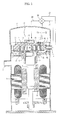
- FIG. 1 is a sectional view illustrating a scroll compressor according to an embodiment of the present invention.
- a scroll compressor 1 includes a housing 2, a drive unit, and a compression unit.
- the housing 2 is provided at one side thereof with an outlet port 3, through which a compressed refrigerant is discharged to the outside.
- the housing 2 is also provided at one side thereof with an inlet port 4, through which a refrigerant is introduced.
- the drive unit includes a stator 5 forcibly fitted in the lower side of the housing 2 and a rotor 6 rotatably disposed at the middle of the stator 5.
- An eccentric part 8, which eccentrically rotates, is provided at the upper end of a drive shaft 7.
- the compression unit includes a frame 9 fitted on the drive shaft 7 and fixed to the upper end of the inner circumference of the housing 2, a swivel scroll 30 driven by the drive shaft 7, the swivel scroll 30 having a spiral type swivel scroll wrap 31 formed at the top thereof, and a stationary scroll 20 having a stationary scroll wrap 21 formed at the bottom thereof, the stationary scroll wrap 21 engaging with the swivel scroll wrap 31.
- the stationary scroll 20 is fixed to the upper side of the frame 9, and the swivel scroll 30 swivels at the lower side of the stationary scroll 20 so that the stationary scroll wrap 21 engages with the swivel scroll wrap 31.
- the compressed high-pressure refrigerant is discharged to a discharge chamber 42 through a discharge port 23 of the stationary scroll 20.
- a first middle pressure region 44 communicating with a point of the compression chamber 40 and a second middle pressure region 45 communicating with another point of the compression chamber 40 are defined in the stationary scroll 20.
- the first middle pressure region 44 communicates with the inner part of the compression chamber 40 so that higher pressure is formed in the first middle pressure region 44 than in the second middle pressure region 45. That is, the first middle pressure region 44 is closer to the discharge chamber 42 than the second middle pressure region 45.
- the scroll compressor further includes a back pressure adjustment device 50.
- the back pressure adjustment device 50 communicates with the first middle pressure region 44 through a first middle pressure passage 51. Also, the back pressure adjustment device 50 communicates with the second middle pressure region 45 through a second middle pressure passage 52.
- the back pressure adjustment device 50 communicates with the back pressure chamber 43 through a back pressure passage 53.
- the back pressure adjustment device 50 communicates with the suction chamber 41 through a suction pressure passage 55.
- the back pressure adjustment device 50 communicates with the discharge chamber 42 through a discharge pressure passage 54.
- FIG. 2 is a sectional view of the back pressure adjustment device of the scroll compressor of FIG. 1 illustrating an open state of a first path
- FIG. 3 is a sectional view of the back pressure adjustment device of the scroll compressor of FIG. 1 illustrating an open state of a second path
- FIG. 4 is a sectional view illustrating a piston of the scroll compressor of FIG. 1
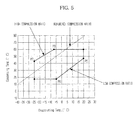
- FIG. 5 is an explanatory view of a reference compression ratio for mode conversion.
- the back pressure adjustment device 50 includes a cylinder 56 and a piston 60 disposed in the cylinder 56.
- the piston 60 is disposed in the cylinder 56 so that the piston 60 vertically reciprocates.
- the upper part of the cylinder 56 communicates with the discharge chamber 42 through the discharge pressure passage 54 so that discharge pressure Pd is applied to the upper end 64 of the piston 60.
- the lower part of the cylinder 56 communicates with the suction chamber 41 through the suction pressure passage 55 so that suction pressure Ps is applied to the lower end 65 of the piston 60.
- the piston 60 may move upward or downward based on a compression ratio of discharge pressure Pd to suction pressure Ps.
- the diameter D1 of the upper end 64 of the piston 60 and the diameter D2 of the lower end 65 of the piston 60 may be appropriately designed to decide a reference compression ratio at which the piston 60 moves upward and downward.
- the reference compression ratio may be set to a predetermined ratio between a high compression ratio and a low compression ratio as shown in FIG. 5 .
- the horizontal axis indicates evaporating temperature and the vertical axis indicates condensing temperature.
- the lower compression ratio is approximately distributed between point P5 and point P6, and the high compression ratio is approximately distributed between point P2 and point P3.
- the diameter D1 of the upper end 64 of the piston 60 is designed to be less than the diameter D2 of the lower end 65 of the piston 60.
- the cylinder 56 has a first path Pa1, through which the first middle pressure passage 51 communicates with the back pressure passage 53 and thus the first middle pressure region 44 communicates with the back pressure chamber 43.
- the cylinder 56 has a second path Pa2, through which the second middle pressure passage 52 communicates with the back pressure passage 53 and thus the second middle pressure region 45 communicates with the back pressure chamber 43.
- first middle pressure Pm1 is applied to the back pressure chamber 43.
- second middle pressure Pm2 is applied to the back pressure chamber 43.
- the first path Pa1 and the second path Pa2 are selectively opened and closed by the piston 60.
- the piston 60 includes a first opening and closing part 61 to open and close the first path Pa1 and a second opening and closing part 62 to open and close the second path Pa2.
- the first opening and closing part 61 and the second opening and closing part 62 are connected to each other via a connection part 63.
- the first opening and closing part 61 and the second opening and closing part 62 are in tight contact with the inner circumference of the cylinder 56.
- the connection part 63 may have a diameter less than that of the inner circumference of the cylinder 56 to form the first path Pa1 or the second path Pa2.
- the cylinder 56 is formed so that the upper inner circumference 57 of the cylinder 56 has a diameter less than that of the lower inner circumference 58 of the cylinder 56 so as to correspond to the shape of the piston 60.
- a seat 59 having a diameter less than that of the lower end 65 of the piston to prevent separation of the piston 60 may be formed at the lower end of the cylinder 56.
- the back pressure adjustment device 50 with the above-stated construction may automatically apply the first middle pressure Pm1 or the second middle pressure Pm2, which is less than the first middle pressure Pm1, to the back pressure chamber 43 according to a compression ratio.
- the drive shaft 7 fixed to the rotor 6 is rotated by electromotive force generated by the stator 5 with the result that the swivel scroll 30 fitted in the eccentric part 9 provided at the upper end of the drive shaft 7 swivels in a state in which the swivel scroll 30 is engaged with the stationary scroll 20.
- the compressed high-pressure refrigerant is discharged to the outside through the outlet port 3 via the discharge chamber 42.
- Second middle pressure Pm2 which is relatively low, is applied to the back pressure chamber 43 through the open second path Pa2.
- the magnitude of back pressure is adjusted at the high compression ratio and the low compression ratio. Consequently, the magnitude of back pressure is appropriately maintained although the compression ratio is changed, and therefore, the operating range of the scroll compressor is widened.
Landscapes
- Engineering & Computer Science (AREA)
- Mechanical Engineering (AREA)
- General Engineering & Computer Science (AREA)
- Rotary Pumps (AREA)
- Applications Or Details Of Rotary Compressors (AREA)
Applications Claiming Priority (1)
| Application Number | Priority Date | Filing Date | Title |
|---|---|---|---|
| KR1020110001617A KR101827829B1 (ko) | 2011-01-07 | 2011-01-07 | 스크롤 압축기 |
Publications (3)
| Publication Number | Publication Date |
|---|---|
| EP2474741A2 true EP2474741A2 (de) | 2012-07-11 |
| EP2474741A3 EP2474741A3 (de) | 2015-04-15 |
| EP2474741B1 EP2474741B1 (de) | 2016-07-06 |
Family
ID=45444430
Family Applications (1)
| Application Number | Title | Priority Date | Filing Date |
|---|---|---|---|
| EP11194412.0A Not-in-force EP2474741B1 (de) | 2011-01-07 | 2011-12-20 | Spiralverdichter mit einer Gegendruckeinstellvorrichtung |
Country Status (4)
| Country | Link |
|---|---|
| US (1) | US9133845B2 (de) |
| EP (1) | EP2474741B1 (de) |
| KR (1) | KR101827829B1 (de) |
| CN (1) | CN102588275B (de) |
Cited By (3)
| Publication number | Priority date | Publication date | Assignee | Title |
|---|---|---|---|---|
| EP3263901A4 (de) * | 2015-02-27 | 2018-01-24 | Daikin Industries, Ltd. | Spiralverdichter |
| WO2019092024A1 (de) * | 2017-11-07 | 2019-05-16 | SANDEN International Europe Ltd. | Spiralverdichter mit optimiertem anpressdruck |
| CN116221107A (zh) * | 2022-11-18 | 2023-06-06 | 珠海格力电器股份有限公司 | 一种涡旋压缩机及包括该涡旋压缩机的空调器 |
Families Citing this family (11)
| Publication number | Priority date | Publication date | Assignee | Title |
|---|---|---|---|---|
| US9982666B2 (en) | 2015-05-29 | 2018-05-29 | Agilient Technologies, Inc. | Vacuum pump system including scroll pump and secondary pumping mechanism |
| KR102166766B1 (ko) * | 2015-08-11 | 2020-10-16 | 삼성전자주식회사 | 압축기 |
| DE102016105302B4 (de) * | 2016-03-22 | 2018-06-14 | Hanon Systems | Steuerstromregelventil, insbesondere für Spiralverdichter in Fahrzeugklimaanlagen oder Wärmepumpen |
| WO2018036380A1 (zh) * | 2016-08-26 | 2018-03-01 | 艾默生环境优化技术(苏州)有限公司 | 涡旋压缩机 |
| JP6903454B2 (ja) * | 2017-03-10 | 2021-07-14 | サンデンホールディングス株式会社 | スクロール型圧縮機 |
| KR102408562B1 (ko) * | 2017-09-01 | 2022-06-14 | 삼성전자주식회사 | 스크롤 압축기 |
| CN108869283A (zh) * | 2018-08-17 | 2018-11-23 | 苏州旋凌科技有限公司 | 一种容量调节涡旋压缩机 |
| CN112682307B (zh) * | 2020-12-29 | 2022-05-10 | 罗伯特·博世有限公司 | 涡旋式压缩机 |
| JP7481640B2 (ja) * | 2022-08-01 | 2024-05-13 | ダイキン工業株式会社 | スクロール圧縮機及び冷凍装置 |
| KR102755917B1 (ko) * | 2022-11-03 | 2025-01-21 | 주식회사 에이티써모 | 배압 조절 밸브 및 이를 가진 전동식 스크롤 압축기 |
| US12313065B2 (en) * | 2023-08-31 | 2025-05-27 | At Thermo Co., Ltd. | Back pressure regulating valve and an electric type of a scroll compressor with the same |
Family Cites Families (12)
| Publication number | Priority date | Publication date | Assignee | Title |
|---|---|---|---|---|
| JPS6075796A (ja) * | 1983-10-03 | 1985-04-30 | Hitachi Ltd | スクロ−ル圧縮機 |
| US5451146A (en) * | 1992-04-01 | 1995-09-19 | Nippondenso Co., Ltd. | Scroll-type variable-capacity compressor with bypass valve |
| US5678985A (en) * | 1995-12-19 | 1997-10-21 | Copeland Corporation | Scroll machine with capacity modulation |
| JPH10325396A (ja) | 1997-05-27 | 1998-12-08 | Mitsubishi Heavy Ind Ltd | スクロール圧縮機及びその背圧制御弁 |
| JP3861594B2 (ja) * | 2000-12-15 | 2006-12-20 | ユニシア ジェーケーシー ステアリングシステム株式会社 | オイルポンプ |
| KR100417419B1 (ko) | 2001-01-29 | 2004-02-05 | 엘지전자 주식회사 | 스크롤 압축기의 역회전 방지장치 |
| KR20030070136A (ko) * | 2001-01-29 | 2003-08-27 | 마쯔시다덴기산교 가부시키가이샤 | 스크롤 압축기 |
| JP4519489B2 (ja) * | 2004-03-15 | 2010-08-04 | 日立アプライアンス株式会社 | スクロール圧縮機 |
| CN100455807C (zh) | 2004-04-28 | 2009-01-28 | 乐金电子(天津)电器有限公司 | 螺旋压缩机 |
| JP5261992B2 (ja) | 2007-06-11 | 2013-08-14 | ダイキン工業株式会社 | スクロール圧縮機 |
| JP2010150967A (ja) * | 2008-12-24 | 2010-07-08 | Toyota Industries Corp | スクロール型圧縮機 |
| JP4614009B1 (ja) | 2009-09-02 | 2011-01-19 | ダイキン工業株式会社 | スクロール圧縮機 |
-
2011
- 2011-01-07 KR KR1020110001617A patent/KR101827829B1/ko not_active Expired - Fee Related
- 2011-12-20 EP EP11194412.0A patent/EP2474741B1/de not_active Not-in-force
- 2011-12-27 US US13/337,745 patent/US9133845B2/en not_active Expired - Fee Related
-
2012
- 2012-01-04 CN CN201210004565.8A patent/CN102588275B/zh not_active Expired - Fee Related
Non-Patent Citations (1)
| Title |
|---|
| None |
Cited By (4)
| Publication number | Priority date | Publication date | Assignee | Title |
|---|---|---|---|---|
| EP3263901A4 (de) * | 2015-02-27 | 2018-01-24 | Daikin Industries, Ltd. | Spiralverdichter |
| US10502211B2 (en) | 2015-02-27 | 2019-12-10 | Daikin Industries, Ltd. | Scroll-type compressor having injection passage part to establish communication between an external injection pipe and compression chamber, and relief mechanism to establish communication between compression chamber and back pressure chamber |
| WO2019092024A1 (de) * | 2017-11-07 | 2019-05-16 | SANDEN International Europe Ltd. | Spiralverdichter mit optimiertem anpressdruck |
| CN116221107A (zh) * | 2022-11-18 | 2023-06-06 | 珠海格力电器股份有限公司 | 一种涡旋压缩机及包括该涡旋压缩机的空调器 |
Also Published As
| Publication number | Publication date |
|---|---|
| KR20120080275A (ko) | 2012-07-17 |
| CN102588275B (zh) | 2016-02-10 |
| US20120177522A1 (en) | 2012-07-12 |
| US9133845B2 (en) | 2015-09-15 |
| CN102588275A (zh) | 2012-07-18 |
| EP2474741B1 (de) | 2016-07-06 |
| EP2474741A3 (de) | 2015-04-15 |
| KR101827829B1 (ko) | 2018-02-12 |
Similar Documents
| Publication | Publication Date | Title |
|---|---|---|
| EP2474741A2 (de) | Spiralverdichter mit einer Gegendruckeinstellvorrichtung | |
| US7695257B2 (en) | Apparatus for preventing vacuum of scroll compressor | |
| KR101738456B1 (ko) | 스크롤 압축기 | |
| KR102408562B1 (ko) | 스크롤 압축기 | |
| KR101917697B1 (ko) | 스크롤 압축기의 밸브 장치 | |
| JP4706617B2 (ja) | 圧縮機の吸入絞り弁 | |
| KR101467024B1 (ko) | 스크롤 압축기 | |
| US20220025884A1 (en) | High pressure scroll compressor | |
| KR101909606B1 (ko) | 스크롤 압축기 | |
| JP6150983B2 (ja) | 背圧調節装置を有するスクロール圧縮機 | |
| KR101718033B1 (ko) | 압축기 | |
| JP2013139714A (ja) | スクロール圧縮機 | |
| US10533555B2 (en) | Scroll compressor | |
| KR100608863B1 (ko) | 회전식 압축기의 바이패스밸브 구조 | |
| JP7854145B2 (ja) | 背圧調節弁及びそれを有した電動式スクロール圧縮機 | |
| KR101866735B1 (ko) | 사판식 압축기 | |
| KR100594931B1 (ko) | 스크롤 압축기의 고진공 방지장치 | |
| KR101852447B1 (ko) | 사판식 압축기 | |
| KR101533253B1 (ko) | 스크롤 압축기 | |
| KR101877259B1 (ko) | 가변 용량형 사판식 압축기 | |
| CN115803524A (zh) | 斜板式压缩机 | |
| KR20080045558A (ko) | 밀폐형 압축기 | |
| JP2020056348A (ja) | スクロール圧縮機 | |
| KR20140015184A (ko) | 사판식 압축기 | |
| KR20170035255A (ko) | 가변 용량형 사판식 압축기 |
Legal Events
| Date | Code | Title | Description |
|---|---|---|---|
| PUAI | Public reference made under article 153(3) epc to a published international application that has entered the european phase |
Free format text: ORIGINAL CODE: 0009012 |
|
| AK | Designated contracting states |
Kind code of ref document: A2 Designated state(s): AL AT BE BG CH CY CZ DE DK EE ES FI FR GB GR HR HU IE IS IT LI LT LU LV MC MK MT NL NO PL PT RO RS SE SI SK SM TR |
|
| AX | Request for extension of the european patent |
Extension state: BA ME |
|
| RAP1 | Party data changed (applicant data changed or rights of an application transferred) |
Owner name: SAMSUNG ELECTRONICS CO., LTD. |
|
| PUAL | Search report despatched |
Free format text: ORIGINAL CODE: 0009013 |
|
| AK | Designated contracting states |
Kind code of ref document: A3 Designated state(s): AL AT BE BG CH CY CZ DE DK EE ES FI FR GB GR HR HU IE IS IT LI LT LU LV MC MK MT NL NO PL PT RO RS SE SI SK SM TR |
|
| AX | Request for extension of the european patent |
Extension state: BA ME |
|
| RIC1 | Information provided on ipc code assigned before grant |
Ipc: F04C 27/00 20060101ALI20150309BHEP Ipc: F04C 18/02 20060101AFI20150309BHEP Ipc: F04C 23/00 20060101ALI20150309BHEP |
|
| 17P | Request for examination filed |
Effective date: 20151015 |
|
| RBV | Designated contracting states (corrected) |
Designated state(s): AL AT BE BG CH CY CZ DE DK EE ES FI FR GB GR HR HU IE IS IT LI LT LU LV MC MK MT NL NO PL PT RO RS SE SI SK SM TR |
|
| GRAP | Despatch of communication of intention to grant a patent |
Free format text: ORIGINAL CODE: EPIDOSNIGR1 |
|
| INTG | Intention to grant announced |
Effective date: 20160126 |
|
| GRAS | Grant fee paid |
Free format text: ORIGINAL CODE: EPIDOSNIGR3 |
|
| GRAA | (expected) grant |
Free format text: ORIGINAL CODE: 0009210 |
|
| AK | Designated contracting states |
Kind code of ref document: B1 Designated state(s): AL AT BE BG CH CY CZ DE DK EE ES FI FR GB GR HR HU IE IS IT LI LT LU LV MC MK MT NL NO PL PT RO RS SE SI SK SM TR |
|
| REG | Reference to a national code |
Ref country code: GB Ref legal event code: FG4D |
|
| REG | Reference to a national code |
Ref country code: AT Ref legal event code: REF Ref document number: 810941 Country of ref document: AT Kind code of ref document: T Effective date: 20160715 Ref country code: CH Ref legal event code: EP |
|
| REG | Reference to a national code |
Ref country code: IE Ref legal event code: FG4D |
|
| REG | Reference to a national code |
Ref country code: DE Ref legal event code: R096 Ref document number: 602011027902 Country of ref document: DE |
|
| REG | Reference to a national code |
Ref country code: NL Ref legal event code: MP Effective date: 20160706 |
|
| REG | Reference to a national code |
Ref country code: LT Ref legal event code: MG4D |
|
| REG | Reference to a national code |
Ref country code: AT Ref legal event code: MK05 Ref document number: 810941 Country of ref document: AT Kind code of ref document: T Effective date: 20160706 |
|
| PG25 | Lapsed in a contracting state [announced via postgrant information from national office to epo] |
Ref country code: HR Free format text: LAPSE BECAUSE OF FAILURE TO SUBMIT A TRANSLATION OF THE DESCRIPTION OR TO PAY THE FEE WITHIN THE PRESCRIBED TIME-LIMIT Effective date: 20160706 Ref country code: LT Free format text: LAPSE BECAUSE OF FAILURE TO SUBMIT A TRANSLATION OF THE DESCRIPTION OR TO PAY THE FEE WITHIN THE PRESCRIBED TIME-LIMIT Effective date: 20160706 Ref country code: FI Free format text: LAPSE BECAUSE OF FAILURE TO SUBMIT A TRANSLATION OF THE DESCRIPTION OR TO PAY THE FEE WITHIN THE PRESCRIBED TIME-LIMIT Effective date: 20160706 Ref country code: IT Free format text: LAPSE BECAUSE OF FAILURE TO SUBMIT A TRANSLATION OF THE DESCRIPTION OR TO PAY THE FEE WITHIN THE PRESCRIBED TIME-LIMIT Effective date: 20160706 Ref country code: NO Free format text: LAPSE BECAUSE OF FAILURE TO SUBMIT A TRANSLATION OF THE DESCRIPTION OR TO PAY THE FEE WITHIN THE PRESCRIBED TIME-LIMIT Effective date: 20161006 Ref country code: IS Free format text: LAPSE BECAUSE OF FAILURE TO SUBMIT A TRANSLATION OF THE DESCRIPTION OR TO PAY THE FEE WITHIN THE PRESCRIBED TIME-LIMIT Effective date: 20161106 Ref country code: RS Free format text: LAPSE BECAUSE OF FAILURE TO SUBMIT A TRANSLATION OF THE DESCRIPTION OR TO PAY THE FEE WITHIN THE PRESCRIBED TIME-LIMIT Effective date: 20160706 Ref country code: NL Free format text: LAPSE BECAUSE OF FAILURE TO SUBMIT A TRANSLATION OF THE DESCRIPTION OR TO PAY THE FEE WITHIN THE PRESCRIBED TIME-LIMIT Effective date: 20160706 |
|
| PG25 | Lapsed in a contracting state [announced via postgrant information from national office to epo] |
Ref country code: LV Free format text: LAPSE BECAUSE OF FAILURE TO SUBMIT A TRANSLATION OF THE DESCRIPTION OR TO PAY THE FEE WITHIN THE PRESCRIBED TIME-LIMIT Effective date: 20160706 Ref country code: PT Free format text: LAPSE BECAUSE OF FAILURE TO SUBMIT A TRANSLATION OF THE DESCRIPTION OR TO PAY THE FEE WITHIN THE PRESCRIBED TIME-LIMIT Effective date: 20161107 Ref country code: AT Free format text: LAPSE BECAUSE OF FAILURE TO SUBMIT A TRANSLATION OF THE DESCRIPTION OR TO PAY THE FEE WITHIN THE PRESCRIBED TIME-LIMIT Effective date: 20160706 Ref country code: SE Free format text: LAPSE BECAUSE OF FAILURE TO SUBMIT A TRANSLATION OF THE DESCRIPTION OR TO PAY THE FEE WITHIN THE PRESCRIBED TIME-LIMIT Effective date: 20160706 Ref country code: ES Free format text: LAPSE BECAUSE OF FAILURE TO SUBMIT A TRANSLATION OF THE DESCRIPTION OR TO PAY THE FEE WITHIN THE PRESCRIBED TIME-LIMIT Effective date: 20160706 Ref country code: BE Free format text: LAPSE BECAUSE OF FAILURE TO SUBMIT A TRANSLATION OF THE DESCRIPTION OR TO PAY THE FEE WITHIN THE PRESCRIBED TIME-LIMIT Effective date: 20160706 Ref country code: GR Free format text: LAPSE BECAUSE OF FAILURE TO SUBMIT A TRANSLATION OF THE DESCRIPTION OR TO PAY THE FEE WITHIN THE PRESCRIBED TIME-LIMIT Effective date: 20161007 Ref country code: PL Free format text: LAPSE BECAUSE OF FAILURE TO SUBMIT A TRANSLATION OF THE DESCRIPTION OR TO PAY THE FEE WITHIN THE PRESCRIBED TIME-LIMIT Effective date: 20160706 |
|
| REG | Reference to a national code |
Ref country code: DE Ref legal event code: R097 Ref document number: 602011027902 Country of ref document: DE |
|
| PG25 | Lapsed in a contracting state [announced via postgrant information from national office to epo] |
Ref country code: EE Free format text: LAPSE BECAUSE OF FAILURE TO SUBMIT A TRANSLATION OF THE DESCRIPTION OR TO PAY THE FEE WITHIN THE PRESCRIBED TIME-LIMIT Effective date: 20160706 Ref country code: RO Free format text: LAPSE BECAUSE OF FAILURE TO SUBMIT A TRANSLATION OF THE DESCRIPTION OR TO PAY THE FEE WITHIN THE PRESCRIBED TIME-LIMIT Effective date: 20160706 |
|
| PLBE | No opposition filed within time limit |
Free format text: ORIGINAL CODE: 0009261 |
|
| STAA | Information on the status of an ep patent application or granted ep patent |
Free format text: STATUS: NO OPPOSITION FILED WITHIN TIME LIMIT |
|
| PG25 | Lapsed in a contracting state [announced via postgrant information from national office to epo] |
Ref country code: SM Free format text: LAPSE BECAUSE OF FAILURE TO SUBMIT A TRANSLATION OF THE DESCRIPTION OR TO PAY THE FEE WITHIN THE PRESCRIBED TIME-LIMIT Effective date: 20160706 Ref country code: CZ Free format text: LAPSE BECAUSE OF FAILURE TO SUBMIT A TRANSLATION OF THE DESCRIPTION OR TO PAY THE FEE WITHIN THE PRESCRIBED TIME-LIMIT Effective date: 20160706 Ref country code: SK Free format text: LAPSE BECAUSE OF FAILURE TO SUBMIT A TRANSLATION OF THE DESCRIPTION OR TO PAY THE FEE WITHIN THE PRESCRIBED TIME-LIMIT Effective date: 20160706 Ref country code: DK Free format text: LAPSE BECAUSE OF FAILURE TO SUBMIT A TRANSLATION OF THE DESCRIPTION OR TO PAY THE FEE WITHIN THE PRESCRIBED TIME-LIMIT Effective date: 20160706 Ref country code: BG Free format text: LAPSE BECAUSE OF FAILURE TO SUBMIT A TRANSLATION OF THE DESCRIPTION OR TO PAY THE FEE WITHIN THE PRESCRIBED TIME-LIMIT Effective date: 20161006 |
|
| 26N | No opposition filed |
Effective date: 20170407 |
|
| REG | Reference to a national code |
Ref country code: CH Ref legal event code: PL |
|
| PG25 | Lapsed in a contracting state [announced via postgrant information from national office to epo] |
Ref country code: SI Free format text: LAPSE BECAUSE OF FAILURE TO SUBMIT A TRANSLATION OF THE DESCRIPTION OR TO PAY THE FEE WITHIN THE PRESCRIBED TIME-LIMIT Effective date: 20160706 |
|
| PG25 | Lapsed in a contracting state [announced via postgrant information from national office to epo] |
Ref country code: MC Free format text: LAPSE BECAUSE OF FAILURE TO SUBMIT A TRANSLATION OF THE DESCRIPTION OR TO PAY THE FEE WITHIN THE PRESCRIBED TIME-LIMIT Effective date: 20160706 |
|
| REG | Reference to a national code |
Ref country code: FR Ref legal event code: ST Effective date: 20170831 |
|
| REG | Reference to a national code |
Ref country code: IE Ref legal event code: MM4A |
|
| PG25 | Lapsed in a contracting state [announced via postgrant information from national office to epo] |
Ref country code: LU Free format text: LAPSE BECAUSE OF NON-PAYMENT OF DUE FEES Effective date: 20161220 Ref country code: CH Free format text: LAPSE BECAUSE OF NON-PAYMENT OF DUE FEES Effective date: 20161231 Ref country code: FR Free format text: LAPSE BECAUSE OF NON-PAYMENT OF DUE FEES Effective date: 20170102 Ref country code: LI Free format text: LAPSE BECAUSE OF NON-PAYMENT OF DUE FEES Effective date: 20161231 |
|
| PG25 | Lapsed in a contracting state [announced via postgrant information from national office to epo] |
Ref country code: IE Free format text: LAPSE BECAUSE OF NON-PAYMENT OF DUE FEES Effective date: 20161220 |
|
| PG25 | Lapsed in a contracting state [announced via postgrant information from national office to epo] |
Ref country code: HU Free format text: LAPSE BECAUSE OF FAILURE TO SUBMIT A TRANSLATION OF THE DESCRIPTION OR TO PAY THE FEE WITHIN THE PRESCRIBED TIME-LIMIT; INVALID AB INITIO Effective date: 20111220 Ref country code: CY Free format text: LAPSE BECAUSE OF FAILURE TO SUBMIT A TRANSLATION OF THE DESCRIPTION OR TO PAY THE FEE WITHIN THE PRESCRIBED TIME-LIMIT Effective date: 20160706 |
|
| PG25 | Lapsed in a contracting state [announced via postgrant information from national office to epo] |
Ref country code: TR Free format text: LAPSE BECAUSE OF FAILURE TO SUBMIT A TRANSLATION OF THE DESCRIPTION OR TO PAY THE FEE WITHIN THE PRESCRIBED TIME-LIMIT Effective date: 20160706 Ref country code: MK Free format text: LAPSE BECAUSE OF FAILURE TO SUBMIT A TRANSLATION OF THE DESCRIPTION OR TO PAY THE FEE WITHIN THE PRESCRIBED TIME-LIMIT Effective date: 20160706 |
|
| PG25 | Lapsed in a contracting state [announced via postgrant information from national office to epo] |
Ref country code: MT Free format text: LAPSE BECAUSE OF NON-PAYMENT OF DUE FEES Effective date: 20161220 |
|
| PG25 | Lapsed in a contracting state [announced via postgrant information from national office to epo] |
Ref country code: AL Free format text: LAPSE BECAUSE OF FAILURE TO SUBMIT A TRANSLATION OF THE DESCRIPTION OR TO PAY THE FEE WITHIN THE PRESCRIBED TIME-LIMIT Effective date: 20160706 |
|
| PGFP | Annual fee paid to national office [announced via postgrant information from national office to epo] |
Ref country code: DE Payment date: 20201120 Year of fee payment: 10 Ref country code: GB Payment date: 20201125 Year of fee payment: 10 |
|
| REG | Reference to a national code |
Ref country code: DE Ref legal event code: R119 Ref document number: 602011027902 Country of ref document: DE |
|
| GBPC | Gb: european patent ceased through non-payment of renewal fee |
Effective date: 20211220 |
|
| PG25 | Lapsed in a contracting state [announced via postgrant information from national office to epo] |
Ref country code: GB Free format text: LAPSE BECAUSE OF NON-PAYMENT OF DUE FEES Effective date: 20211220 Ref country code: DE Free format text: LAPSE BECAUSE OF NON-PAYMENT OF DUE FEES Effective date: 20220701 |