EP2474745A2 - Entraînement hydraulique à efficicacité énergétique optimisée pour le mouvement linéaire d'un corps de grande masse - Google Patents
Entraînement hydraulique à efficicacité énergétique optimisée pour le mouvement linéaire d'un corps de grande masse Download PDFInfo
- Publication number
- EP2474745A2 EP2474745A2 EP11193675A EP11193675A EP2474745A2 EP 2474745 A2 EP2474745 A2 EP 2474745A2 EP 11193675 A EP11193675 A EP 11193675A EP 11193675 A EP11193675 A EP 11193675A EP 2474745 A2 EP2474745 A2 EP 2474745A2
- Authority
- EP
- European Patent Office
- Prior art keywords
- cylinder
- drive cylinder
- accumulator
- mass body
- control
- Prior art date
- Legal status (The legal status is an assumption and is not a legal conclusion. Google has not performed a legal analysis and makes no representation as to the accuracy of the status listed.)
- Withdrawn
Links
Images


Classifications
-
- F—MECHANICAL ENGINEERING; LIGHTING; HEATING; WEAPONS; BLASTING
- F15—FLUID-PRESSURE ACTUATORS; HYDRAULICS OR PNEUMATICS IN GENERAL
- F15B—SYSTEMS ACTING BY MEANS OF FLUIDS IN GENERAL; FLUID-PRESSURE ACTUATORS, e.g. SERVOMOTORS; DETAILS OF FLUID-PRESSURE SYSTEMS, NOT OTHERWISE PROVIDED FOR
- F15B21/00—Common features of fluid actuator systems; Fluid-pressure actuator systems or details thereof, not covered by any other group of this subclass
- F15B21/14—Energy-recuperation means
-
- F—MECHANICAL ENGINEERING; LIGHTING; HEATING; WEAPONS; BLASTING
- F15—FLUID-PRESSURE ACTUATORS; HYDRAULICS OR PNEUMATICS IN GENERAL
- F15B—SYSTEMS ACTING BY MEANS OF FLUIDS IN GENERAL; FLUID-PRESSURE ACTUATORS, e.g. SERVOMOTORS; DETAILS OF FLUID-PRESSURE SYSTEMS, NOT OTHERWISE PROVIDED FOR
- F15B1/00—Installations or systems with accumulators; Supply reservoir or sump assemblies
- F15B1/02—Installations or systems with accumulators
- F15B1/024—Installations or systems with accumulators used as a supplementary power source, e.g. to store energy in idle periods to balance pump load
-
- F—MECHANICAL ENGINEERING; LIGHTING; HEATING; WEAPONS; BLASTING
- F15—FLUID-PRESSURE ACTUATORS; HYDRAULICS OR PNEUMATICS IN GENERAL
- F15B—SYSTEMS ACTING BY MEANS OF FLUIDS IN GENERAL; FLUID-PRESSURE ACTUATORS, e.g. SERVOMOTORS; DETAILS OF FLUID-PRESSURE SYSTEMS, NOT OTHERWISE PROVIDED FOR
- F15B11/00—Servomotor systems without provision for follow-up action; Circuits therefor
- F15B11/16—Servomotor systems without provision for follow-up action; Circuits therefor with two or more servomotors
- F15B11/22—Synchronisation of the movement of two or more servomotors
-
- F—MECHANICAL ENGINEERING; LIGHTING; HEATING; WEAPONS; BLASTING
- F15—FLUID-PRESSURE ACTUATORS; HYDRAULICS OR PNEUMATICS IN GENERAL
- F15B—SYSTEMS ACTING BY MEANS OF FLUIDS IN GENERAL; FLUID-PRESSURE ACTUATORS, e.g. SERVOMOTORS; DETAILS OF FLUID-PRESSURE SYSTEMS, NOT OTHERWISE PROVIDED FOR
- F15B2211/00—Circuits for servomotor systems
- F15B2211/20—Fluid pressure source, e.g. accumulator or variable axial piston pump
- F15B2211/21—Systems with pressure sources other than pumps, e.g. with a pyrotechnical charge
- F15B2211/212—Systems with pressure sources other than pumps, e.g. with a pyrotechnical charge the pressure sources being accumulators
-
- F—MECHANICAL ENGINEERING; LIGHTING; HEATING; WEAPONS; BLASTING
- F15—FLUID-PRESSURE ACTUATORS; HYDRAULICS OR PNEUMATICS IN GENERAL
- F15B—SYSTEMS ACTING BY MEANS OF FLUIDS IN GENERAL; FLUID-PRESSURE ACTUATORS, e.g. SERVOMOTORS; DETAILS OF FLUID-PRESSURE SYSTEMS, NOT OTHERWISE PROVIDED FOR
- F15B2211/00—Circuits for servomotor systems
- F15B2211/30—Directional control
- F15B2211/305—Directional control characterised by the type of valves
- F15B2211/3056—Assemblies of multiple valves
- F15B2211/30565—Assemblies of multiple valves having multiple valves for a single output member, e.g. for creating higher valve function by use of multiple valves like two 2/2-valves replacing a 5/3-valve
- F15B2211/30575—Assemblies of multiple valves having multiple valves for a single output member, e.g. for creating higher valve function by use of multiple valves like two 2/2-valves replacing a 5/3-valve in a Wheatstone Bridge arrangement (also half bridges)
-
- F—MECHANICAL ENGINEERING; LIGHTING; HEATING; WEAPONS; BLASTING
- F15—FLUID-PRESSURE ACTUATORS; HYDRAULICS OR PNEUMATICS IN GENERAL
- F15B—SYSTEMS ACTING BY MEANS OF FLUIDS IN GENERAL; FLUID-PRESSURE ACTUATORS, e.g. SERVOMOTORS; DETAILS OF FLUID-PRESSURE SYSTEMS, NOT OTHERWISE PROVIDED FOR
- F15B2211/00—Circuits for servomotor systems
- F15B2211/30—Directional control
- F15B2211/305—Directional control characterised by the type of valves
- F15B2211/3056—Assemblies of multiple valves
- F15B2211/30565—Assemblies of multiple valves having multiple valves for a single output member, e.g. for creating higher valve function by use of multiple valves like two 2/2-valves replacing a 5/3-valve
- F15B2211/3058—Assemblies of multiple valves having multiple valves for a single output member, e.g. for creating higher valve function by use of multiple valves like two 2/2-valves replacing a 5/3-valve having additional valves for interconnecting the fluid chambers of a double-acting actuator, e.g. for regeneration mode or for floating mode
-
- F—MECHANICAL ENGINEERING; LIGHTING; HEATING; WEAPONS; BLASTING
- F15—FLUID-PRESSURE ACTUATORS; HYDRAULICS OR PNEUMATICS IN GENERAL
- F15B—SYSTEMS ACTING BY MEANS OF FLUIDS IN GENERAL; FLUID-PRESSURE ACTUATORS, e.g. SERVOMOTORS; DETAILS OF FLUID-PRESSURE SYSTEMS, NOT OTHERWISE PROVIDED FOR
- F15B2211/00—Circuits for servomotor systems
- F15B2211/30—Directional control
- F15B2211/305—Directional control characterised by the type of valves
- F15B2211/3056—Assemblies of multiple valves
- F15B2211/3059—Assemblies of multiple valves having multiple valves for multiple output members
-
- F—MECHANICAL ENGINEERING; LIGHTING; HEATING; WEAPONS; BLASTING
- F15—FLUID-PRESSURE ACTUATORS; HYDRAULICS OR PNEUMATICS IN GENERAL
- F15B—SYSTEMS ACTING BY MEANS OF FLUIDS IN GENERAL; FLUID-PRESSURE ACTUATORS, e.g. SERVOMOTORS; DETAILS OF FLUID-PRESSURE SYSTEMS, NOT OTHERWISE PROVIDED FOR
- F15B2211/00—Circuits for servomotor systems
- F15B2211/70—Output members, e.g. hydraulic motors or cylinders or control therefor
- F15B2211/705—Output members, e.g. hydraulic motors or cylinders or control therefor characterised by the type of output members or actuators
- F15B2211/7051—Linear output members
- F15B2211/7053—Double-acting output members
- F15B2211/7054—Having equal piston areas
-
- F—MECHANICAL ENGINEERING; LIGHTING; HEATING; WEAPONS; BLASTING
- F15—FLUID-PRESSURE ACTUATORS; HYDRAULICS OR PNEUMATICS IN GENERAL
- F15B—SYSTEMS ACTING BY MEANS OF FLUIDS IN GENERAL; FLUID-PRESSURE ACTUATORS, e.g. SERVOMOTORS; DETAILS OF FLUID-PRESSURE SYSTEMS, NOT OTHERWISE PROVIDED FOR
- F15B2211/00—Circuits for servomotor systems
- F15B2211/70—Output members, e.g. hydraulic motors or cylinders or control therefor
- F15B2211/71—Multiple output members, e.g. multiple hydraulic motors or cylinders
- F15B2211/7107—Multiple output members, e.g. multiple hydraulic motors or cylinders the output members being mechanically linked
-
- F—MECHANICAL ENGINEERING; LIGHTING; HEATING; WEAPONS; BLASTING
- F15—FLUID-PRESSURE ACTUATORS; HYDRAULICS OR PNEUMATICS IN GENERAL
- F15B—SYSTEMS ACTING BY MEANS OF FLUIDS IN GENERAL; FLUID-PRESSURE ACTUATORS, e.g. SERVOMOTORS; DETAILS OF FLUID-PRESSURE SYSTEMS, NOT OTHERWISE PROVIDED FOR
- F15B2211/00—Circuits for servomotor systems
- F15B2211/80—Other types of control related to particular problems or conditions
- F15B2211/85—Control during special operating conditions
- F15B2211/851—Control during special operating conditions during starting
-
- F—MECHANICAL ENGINEERING; LIGHTING; HEATING; WEAPONS; BLASTING
- F15—FLUID-PRESSURE ACTUATORS; HYDRAULICS OR PNEUMATICS IN GENERAL
- F15B—SYSTEMS ACTING BY MEANS OF FLUIDS IN GENERAL; FLUID-PRESSURE ACTUATORS, e.g. SERVOMOTORS; DETAILS OF FLUID-PRESSURE SYSTEMS, NOT OTHERWISE PROVIDED FOR
- F15B2211/00—Circuits for servomotor systems
- F15B2211/80—Other types of control related to particular problems or conditions
- F15B2211/85—Control during special operating conditions
- F15B2211/853—Control during special operating conditions during stopping
-
- F—MECHANICAL ENGINEERING; LIGHTING; HEATING; WEAPONS; BLASTING
- F15—FLUID-PRESSURE ACTUATORS; HYDRAULICS OR PNEUMATICS IN GENERAL
- F15B—SYSTEMS ACTING BY MEANS OF FLUIDS IN GENERAL; FLUID-PRESSURE ACTUATORS, e.g. SERVOMOTORS; DETAILS OF FLUID-PRESSURE SYSTEMS, NOT OTHERWISE PROVIDED FOR
- F15B2211/00—Circuits for servomotor systems
- F15B2211/80—Other types of control related to particular problems or conditions
- F15B2211/88—Control measures for saving energy
Definitions
- the invention relates to a hydraulically driven arrangement for linear movement of a mass body, consisting of two parallel to each other, each having a piston with at least one arranged to interact with the mass body piston rod having double-acting cylinders, one of the cylinders as a control cylinder for the control of a Acceleration phase, a driving phase and a braking phase having movement of the mass body is set up and the other cylinder is connected as a drive cylinder to a hydraulic accumulator as an energy storage such that the accumulator during the acceleration phase of the mass body provides the drive power for the drive cylinder and the drive cylinder in the braking phase of the Mass body as a pump for charging the hydraulic accumulator is used.
- the device described therein relates to a hydraulically operated working machine, which by means of a double acting and connected by means of a one-sided piston rod with a working device working cylinder causes a raising and lowering of the working device.
- the two rod-side, smaller displacements of both the drive cylinder and the control cylinder are fluidly connected to each other and connected together to a hydraulic control circuit. This is to ensure that the displaced from the rodless larger displacement of the working cylinder when lowering the working fluid can be completely stored in the accumulator.
- a similar arrangement of two working cylinders is in the DE 103 15 071 A1 described.
- two each double-acting cylinder with one-sided piston rod connected in a parallel arrangement with mutual use with a hinge assembly of a working tool.
- Each cylinder is connected via directional control valves both with the pump and with an accumulator, so that the output in the drive case with Kolbenausschub from the accumulator fluid supplement or replace supplied by the pump fluid flow.
- the accumulator is recharged by a corresponding insertion movement of the pistons of the two working cylinders.
- the working cylinder as well as pump and accumulator are connected to a single hydraulic control circuit.
- a hydraulic drive for an injection molding machine or press in which in each case at least a first and a second drive cylinder are provided.
- the first drive cylinder is connected to a control circuit with a pump, while the second drive cylinder is connected to an accumulator, which is switched on when needed.
- Such an application arises for example from the DE 10 2008 059 436 B3 in which a hydraulic control valve for a single-sided differential cylinder is described.
- a piston having a one-sided piston rod exhibiting, double-acting cylinder is used for linear movement of a mass body such as an inlet and pressure flap in plastic injection molding machines, wherein the piston rod of the working cylinder for driving the mass body is connected thereto.
- a mass body such as an inlet and pressure flap in plastic injection molding machines
- the piston rod of the working cylinder for driving the mass body is connected thereto.
- the DE 10 2008 059 436 B3 described control valve is the forward drive with an extension of the Controlled piston rod and the reverse drive with retraction of the piston rod, each movement comprises an acceleration phase, a driving phase and a braking phase to reach the end position of the mass body.
- the invention is based on the object, a hydraulically driven arrangement with energy recovery according to the generic features for the linear movement of a corresponding to the DE 10 2008 059 436 B3 used mass in their two directions of movement usable.
- the invention provides in a first embodiment for a piston with one-sided and in the sense of a reciprocating motion of the mass body respectively coupled to the mass body piston rod, that control cylinder and drive cylinder each by means of hydraulically separated, independent and each having a control valve or a control valve arrangement exhibiting Control circuits are controlled, wherein the drive cylinder associated control valve assembly has three control edges and the small displacement of the drive cylinder via the control valve assembly with the accumulator and the large displacement of the drive cylinder via the control valve assembly with either the accumulator or with the tank can be connected.
- a second embodiment of the invention provides that the control cylinder and the drive cylinder each have a piston with piston rods set on both sides for forming symmetrical piston surfaces, of which in each case a piston rod is coupled to the mass body in the sense of a reciprocating movement of the mass body; in adaptation to this is in turn provided that control cylinder and drive cylinder are each controlled by means of hydraulically separated, independent and each control valve or a control valve arrangement auf josder control circuits, wherein the drive cylinder associated control valve assembly has four control edges and both the small displacement and the large displacement the drive cylinder via the control valve assembly are selectively connectable to the accumulator or to the tank.
- the control circuit for the control of the drive cylinder causes a charging of the accumulator in both directions of movement of the piston in the drive cylinder.
- the drive cylinder need not impart additional drive energy; here the motion thrust mediated by the control cylinder is sufficient.
- control cylinder and drive cylinder whose piston surfaces together should correspond approximately to the piston surface of a single working cylinder according to the prior art, so that control cylinder and drive cylinder each can be designed with smaller dimensions compared to the prior art. This also achieves a corresponding saving.
- the displacement of the control cylinder via a hydraulic control valve with a pump and / or a tank are connected, as in principle from the already mentioned DE 10 2008 059 436 B3 is known for a Häzylindcr as the sole drive for a mass body.
- the hydraulic control valve has a regenerative circuit for the displaced during the piston movement of the small displacement of the control cylinder fluid, as also from the above DE 10 2008 059 436 B3 is known in detail and therefore belongs to the state of the art.
- control cylinder connected in parallel working cylinder as a drive cylinder is provided according to an embodiment of the invention, that the displacements of the drive cylinder are each connectable via a hydraulic control valve arrangement optionally with the accumulator and / or a tank.
- a feedback circuit with an infeed of the displaced from one cylinder displacement fluid in the other displacement of the drive cylinder is provided according to an embodiment of the invention that between the accumulator and its connection to the two displacements the drive cylinder associated control edges of the control valve assembly is provided a connecting the displacement of the drive cylinder flow line.
- a circuit design for provided with one-sided piston rod working cylinder can be provided that when extending the piston rods of the control cylinder and drive cylinder during the acceleration phase of the mass body opens the connection between the filled with biased fluid accumulator and the large capacity of the drive cylinder on the associated control edge of the control valve assembly and at the same time the connection between the small displacement of the drive cylinder and the flow line is opened, so that the stored in the accumulator and the displaced from the small displacement of the drive cylinder in the piston movement fluid is fed into the large displacement of the drive cylinder, and wherein during the braking phase the mass body on the one hand, the connection between the large displacement of the drive cylinder and the tank open and the connection between the flow line and the large displacement the drive cylinder are locked and on the other hand, the connection between the small displacement of the drive cylinder and the flow line with the battery connected thereto remains open, so that the accumulator is charged by the displaced from the small displacement of the drive cylinder fluid.
- a retraction of the mass body retraction of the piston rod of the control cylinder and the drive cylinder is provided as part of such a circuit further that during the acceleration phase of the mass body, the connection between the large displacement of the drive cylinder and the tank while blocking the Connection of the large capacity to the accumulator and the connection between the accumulator and the small displacement of the drive cylinder are open, so that the fluid released from the accumulator fluid acts on the small displacement of the drive cylinder, and wherein during the braking phase of the mass body, the connection between the large displacement of the drive cylinder and the flow line with the accumulator connected thereto is opened while blocking the connection to the tank, so that the accumulator by the large displacement of the drive cylinder v erdrfitte fluid is charged.
- the drive cylinder is only required during the acceleration phase and during the braking phase of the mass body, wherein during the driving phase to maintain the driving speed of the mass body of the drive via the control cylinder is sufficient.
- at both ends of the linear movement path of the mass body each have a drive cylinder with an associated, whose connections to the accumulator and the tank comprehensive hydraulic control circuit is arranged, the mass body facing piston rods only during the braking phase and the acceleration phase of the mass body interact with this, wherein the associated piston rod of the control cylinder is coupled to it over the entire movement path of the mass body.
- each of the two drive cylinder is associated with a controllable via an intermediate control valve assembly accumulator.
- the two drive cylinders are connected via their associated control valve assemblies to a common accumulator.
- control valve assembly for controlling the drive cylinder of individual in each case in the leading from the displacements of the drive cylinder to the accumulator and the tank lines 2/2-way valves is formed or alternatively that the control valve assembly for controlling the drive cylinder consists of a one hand on the displacement and on the other hand connected to the tank and the accumulator piston valve. Any other version of a functional hydraulic control valve may be provided.
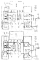
- control cylinder 11 For its control, the control cylinder 11 is connected to a control valve 13, wherein the from the large displacement 19 and the small displacement 20 to the associated terminals of the control valve 13 respectively leading lines 21 and 22 via four formed in the control valve control edges 16 each with a pump 14th or a tank 15 are to be connected.
- control valve 13 For the production of in the DE 10 2008 059 436 B3 already described return line from the control valve 13 to the large displacement 19 of the control cylinder 11 leading line 22a is provided, by means of which in the assigned position of the control valve 13 of the small displacement 20 of the control cylinder 11 is directly connected to the large displacement 19.
- the drive cylinder 12 is associated with a control valve assembly 23 whose connections are connected on the one hand via lines 27 and 28 to the large displacement 19 and the small displacement 20 of the drive cylinder 12.
- the terminals of the control valve assembly 23 with a tank 24 and with a hydraulic accumulator 25 connected.
- three control edges 26 are provided so that the small displacement 20 of the drive cylinder 12 is to be connected to the accumulator 25 and the large displacement 19 is selectively connectable to the accumulator 25 or the tank 24.
- the leading from the large displacement 19 of the drive cylinder 12 to the control valve assembly 23 line 27 branches into two lines 27a and 27b, which are guided to the corresponding control edges 26 corresponding terminals of the control valve assembly.
- FIGS. 2 to 6 are now the adjusting during the operating states of the mass body switching states or fluid flows shown.
- FIG. 2 The rest position of the mass body 10 before the beginning of its movement phase shows the piston collars 33 of the spool 32 of the piston valve designed as a control valve 13 for the control cylinder 11, the connecting lines 21 and 22 to the large displacement 19 and small displacement 20 of the control cylinder 11 from, so that the Control cylinder 11 is at a standstill. How to continue FIG.
- the your drive cylinder 12 associated control valve assembly 23 consists of three switched in the respective cable paths 2/2-way valves in the form of inserted into the conduit paths cartridge valves, namely a 2/2-way valve 34 shutting off the conduction path 27a to the tank 24, a 2/2-way valve 35 connected in the connection 27b between the large displacement 19 of the drive cylinder 12 and the accumulator 25 or the flow line 29, and an in the connecting line 28 between the small displacement 20 of the drive cylinder 12 and the accumulator 25 switched 2/2-way valve 36.
- the accumulator 25 is loaded with tensioned fluid, and all three 2/2-way valves 34, 35, 36 are located in the closed position.
- the drive cylinder 12 is at rest.
- the two 2/2-way valves 35 and 36 are opened, so that on the one hand, the accumulator 25 is interconnected with the large displacement 19 of the drive cylinder 12 and on the other hand, during the forward movement of the piston 17 in Drive cylinder 12 from the small displacement 20 displaced fluid via the line 28 and the flow line 29 is also fed into the large displacement 19 of the drive cylinder 12. If the drive energy stored in the accumulator 25 is consumed after completion of the acceleration phase, the control cylinder 11 ensures the forward movement of the mass body 10, wherein the fluid displaced from the small displacement 20 of the drive cylinder 12 continues to flow into the large displacement 19 of the drive cylinder 12.
- control valve 13 for the control cylinder 11 and the control valve assembly 23 for the drive cylinder 12 are transferred to their closed positions, and it turns the idle state or standstill according to FIG. 2 one.
- both the control valve 13 and the control valve assembly 23 are transferred to their full closed position, so that the in FIG. 2 shown rest state or standstill again sets.
- the invention can also be applied to a design of control cylinder 11 and drive cylinder 12, each having a piston 17 and both sides attached thereto piston rods 18a and 18b, wherein the one piston rod 18a is connected to the mass body 10 and the other piston rod 18b runs empty , Since in this case the piston surfaces are the same size, the associated hydraulic circuit requires an adaptation to the effect that dispense with a feedback circuit in the control valve 13 for the control cylinder 11 and instead the small displacement 19 is assigned a further tank port 15 a. Insofar as the same applies to the valve arrangement 23 of the drive cylinder 12 with an additional tank connection 24a, the control valve arrangement 23 has four control edges 26. However, the circuit of the control edges 26 takes place in principle as well as to the FIGS. 2 to 6 described in detail.
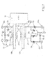
- FIG. 8 an embodiment of the invention shown in which at both ends of the linear path of movement of the mass body 10 are each a drive cylinder 12a and a drive cylinder 12b are arranged.
- the piston rods 18 of the two drive cylinders 12a and 12b are designed to be correspondingly short, so that starting from the in FIG. 8 shown operating position after completion of the acceleration phase of the mass body 10 lifts off the piston rod 18 of the drive cylinder 12a and impinges on the piston rod 18 of the opposite drive cylinder 12b at the beginning of the braking phase.
- the two drive cylinders 12a and 12b are associated with corresponding hydraulic circuits, such as FIG. 1 described, so that each perform the switching operations, as to the FIGS. 2 to 6 described in detail.
- the drive cylinders 12a and 12b each own accumulators 25 are assigned.
- the two drive cylinders 12a and 12b each have a common accumulator 25 is assigned to each of which a corresponding line is performed.
- changes in the functional sequence do not result from this.
Landscapes
- Engineering & Computer Science (AREA)
- Physics & Mathematics (AREA)
- Fluid Mechanics (AREA)
- Mechanical Engineering (AREA)
- General Engineering & Computer Science (AREA)
- Chemical & Material Sciences (AREA)
- Analytical Chemistry (AREA)
- Fluid-Pressure Circuits (AREA)
Applications Claiming Priority (1)
| Application Number | Priority Date | Filing Date | Title |
|---|---|---|---|
| DE201110008145 DE102011008145B3 (de) | 2011-01-08 | 2011-01-08 | Energieeffizienter hydraulischer Antrieb für die Linearbewegung eines Massekörpers |
Publications (2)
| Publication Number | Publication Date |
|---|---|
| EP2474745A2 true EP2474745A2 (fr) | 2012-07-11 |
| EP2474745A3 EP2474745A3 (fr) | 2014-04-30 |
Family
ID=45350682
Family Applications (1)
| Application Number | Title | Priority Date | Filing Date |
|---|---|---|---|
| EP11193675.3A Withdrawn EP2474745A3 (fr) | 2011-01-08 | 2011-12-15 | Entraînement hydraulique à efficicacité énergétique optimisée pour le mouvement linéaire d'un corps de grande masse |
Country Status (3)
| Country | Link |
|---|---|
| US (1) | US9021797B2 (fr) |
| EP (1) | EP2474745A3 (fr) |
| DE (1) | DE102011008145B3 (fr) |
Families Citing this family (6)
| Publication number | Priority date | Publication date | Assignee | Title |
|---|---|---|---|---|
| JP5574375B2 (ja) * | 2010-06-30 | 2014-08-20 | キャタピラー エス エー アール エル | エネルギ回生用制御回路および作業機械 |
| DE102011053230B3 (de) * | 2011-09-02 | 2013-01-31 | Parker Hannifin Manufacturing Germany GmbH & Co. KG | Linear arbeitender Massekörperantrieb mit Energierückgewinnung |
| US10570930B2 (en) | 2011-10-10 | 2020-02-25 | Angus Peter Robson | Accumulator |
| US9790962B2 (en) | 2011-10-10 | 2017-10-17 | Angus Peter Robson | Accumulator |
| DE102012101120B4 (de) * | 2012-02-14 | 2013-08-22 | Parker Hannifin Manufacturing Germany GmbH & Co. KG | Hydraulisch angetriebene Anordnung zum linearen Bewegen eines Massekörpers |
| FR3021290B1 (fr) * | 2014-05-20 | 2016-05-27 | O S C Offshore Systems Concepts | Systeme d'entrainement et de guidage d'un joint tournant |
Citations (4)
| Publication number | Priority date | Publication date | Assignee | Title |
|---|---|---|---|---|
| WO1993011363A1 (fr) | 1991-12-04 | 1993-06-10 | Hydac Technology Gmbh | Recuperateur d'energie |
| DE10315071A1 (de) | 2002-05-17 | 2003-11-27 | Caterpillar Inc | Hydraulisches Regenerationssystem |
| DE102005017878B3 (de) | 2005-04-19 | 2006-09-28 | Krauss-Maffei Kunststofftechnik Gmbh | Hydraulische Formschließeinheit |
| DE102008059436B3 (de) | 2008-11-27 | 2010-01-07 | Parker Hannifin Gmbh & Co. Kg | Hydraulisches Steuerventil für einen einseitig arbeitenden Differentialzylinder |
Family Cites Families (4)
| Publication number | Priority date | Publication date | Assignee | Title |
|---|---|---|---|---|
| CA1280669C (fr) * | 1986-06-04 | 1991-02-26 | Ronald Ballantyne | Systeme recuperateur d'energie pour presse |
| DE102004032868A1 (de) * | 2004-07-07 | 2006-02-09 | Liebherr-Hydraulikbagger Gmbh | Bagger und Maschine zum Materialumschlag |
| FR2941976B1 (fr) * | 2009-02-09 | 2011-03-11 | Manu Lorraine | Systeme hydraulique d'engin de manutention ou de terrassement avec accumulateur d'energie |
| US9051944B2 (en) * | 2012-06-15 | 2015-06-09 | Caterpillar Inc. | Hydraulic system and control logic for collection and recovery of energy in a double actuator arrangement |
-
2011
- 2011-01-08 DE DE201110008145 patent/DE102011008145B3/de not_active Expired - Fee Related
- 2011-12-15 EP EP11193675.3A patent/EP2474745A3/fr not_active Withdrawn
-
2012
- 2012-01-03 US US13/342,262 patent/US9021797B2/en active Active
Patent Citations (4)
| Publication number | Priority date | Publication date | Assignee | Title |
|---|---|---|---|---|
| WO1993011363A1 (fr) | 1991-12-04 | 1993-06-10 | Hydac Technology Gmbh | Recuperateur d'energie |
| DE10315071A1 (de) | 2002-05-17 | 2003-11-27 | Caterpillar Inc | Hydraulisches Regenerationssystem |
| DE102005017878B3 (de) | 2005-04-19 | 2006-09-28 | Krauss-Maffei Kunststofftechnik Gmbh | Hydraulische Formschließeinheit |
| DE102008059436B3 (de) | 2008-11-27 | 2010-01-07 | Parker Hannifin Gmbh & Co. Kg | Hydraulisches Steuerventil für einen einseitig arbeitenden Differentialzylinder |
Also Published As
| Publication number | Publication date |
|---|---|
| EP2474745A3 (fr) | 2014-04-30 |
| US9021797B2 (en) | 2015-05-05 |
| US20120192553A1 (en) | 2012-08-02 |
| DE102011008145B3 (de) | 2012-02-02 |
Similar Documents
| Publication | Publication Date | Title |
|---|---|---|
| EP0615583B1 (fr) | Recuperateur d'energie | |
| EP2480405B1 (fr) | Entrainement hydraulique precontraint dote d'une pompe a vitesse variable | |
| DE102011116964A1 (de) | Hydraulische Achse | |
| DE102011008145B3 (de) | Energieeffizienter hydraulischer Antrieb für die Linearbewegung eines Massekörpers | |
| WO2002024441A1 (fr) | Dispositif de commande pour une presse hydraulique et procede pour son fonctionnement | |
| DE102015109840B3 (de) | Kniehebel-Schließeinheit für eine Spritzgießmaschine | |
| DE2726165A1 (de) | Vorrichtung zur erhoehung der ausfahrgeschwindigkeit der kolbenstange eines druckmitteldruck verwendenden hubzylinders | |
| DE102014007439B4 (de) | Pneumatisches Antriebssystem und Verfahren zu seinem Betreiben | |
| DE102017000523B4 (de) | Hydraulikvorrichtung für eine Formgebungsmaschine | |
| DE102013007148B4 (de) | Hydraulischer Pressantrieb mit Energierückspeisung | |
| DE102011054616B3 (de) | Hydraulisch angetriebene Anordnung zum linearen Bewegen eines Massekörpers | |
| CH704896B1 (de) | Hydraulische Antriebsvorrichtung für Presskolben von Hydraulikzylindern einer Pulverpresse. | |
| DE102012101120B4 (de) | Hydraulisch angetriebene Anordnung zum linearen Bewegen eines Massekörpers | |
| DE102018203367A1 (de) | Hydrostatischer Linearantrieb | |
| AT412113B (de) | Hyraulische betätigungsanordnung | |
| DE102012020935A1 (de) | Hydraulische Schaltung | |
| DE102013014074B3 (de) | Ballenpresse | |
| EP2360380B1 (fr) | Soupape de distribution hydraulique pour un cylindre différentiel à simple effet dotée de cinq arêtes de commande | |
| DE112005002528B4 (de) | Hydraulisch betätigte Giesseinheit und Verfahren zu deren Ansteuerung | |
| DE102011053230B3 (de) | Linear arbeitender Massekörperantrieb mit Energierückgewinnung | |
| DE102012107699B3 (de) | Massekörperantrieb mit hydraulischer Energierückgewinnungsschaltung | |
| DE102005041252B4 (de) | Elektrohydraulischer Pressenantrieb | |
| DE102019001211A1 (de) | Hydraulische Steuervorrichtung | |
| DE102024113217A1 (de) | Antriebseinheit | |
| WO2007009561A1 (fr) | Systeme de freinage pour vehicule automobile |
Legal Events
| Date | Code | Title | Description |
|---|---|---|---|
| PUAI | Public reference made under article 153(3) epc to a published international application that has entered the european phase |
Free format text: ORIGINAL CODE: 0009012 |
|
| AK | Designated contracting states |
Kind code of ref document: A2 Designated state(s): AL AT BE BG CH CY CZ DE DK EE ES FI FR GB GR HR HU IE IS IT LI LT LU LV MC MK MT NL NO PL PT RO RS SE SI SK SM TR |
|
| AX | Request for extension of the european patent |
Extension state: BA ME |
|
| PUAL | Search report despatched |
Free format text: ORIGINAL CODE: 0009013 |
|
| AK | Designated contracting states |
Kind code of ref document: A3 Designated state(s): AL AT BE BG CH CY CZ DE DK EE ES FI FR GB GR HR HU IE IS IT LI LT LU LV MC MK MT NL NO PL PT RO RS SE SI SK SM TR |
|
| AX | Request for extension of the european patent |
Extension state: BA ME |
|
| RIC1 | Information provided on ipc code assigned before grant |
Ipc: F15B 21/14 20060101ALI20140324BHEP Ipc: F15B 1/02 20060101AFI20140324BHEP |
|
| STAA | Information on the status of an ep patent application or granted ep patent |
Free format text: STATUS: THE APPLICATION IS DEEMED TO BE WITHDRAWN |
|
| 18D | Application deemed to be withdrawn |
Effective date: 20141031 |