EP2474799A2 - Systèmes de contrôle de la température - Google Patents
Systèmes de contrôle de la température Download PDFInfo
- Publication number
- EP2474799A2 EP2474799A2 EP12150133A EP12150133A EP2474799A2 EP 2474799 A2 EP2474799 A2 EP 2474799A2 EP 12150133 A EP12150133 A EP 12150133A EP 12150133 A EP12150133 A EP 12150133A EP 2474799 A2 EP2474799 A2 EP 2474799A2
- Authority
- EP
- European Patent Office
- Prior art keywords
- temperature
- cooled zone
- cooling system
- control unit
- control
- Prior art date
- Legal status (The legal status is an assumption and is not a legal conclusion. Google has not performed a legal analysis and makes no representation as to the accuracy of the status listed.)
- Withdrawn
Links
- 238000001816 cooling Methods 0.000 claims abstract description 178
- 238000000034 method Methods 0.000 claims abstract description 14
- 230000000694 effects Effects 0.000 claims description 53
- 230000008859 change Effects 0.000 claims description 21
- 238000001514 detection method Methods 0.000 claims description 9
- 230000004044 response Effects 0.000 claims description 8
- 230000005611 electricity Effects 0.000 claims description 3
- 230000007246 mechanism Effects 0.000 description 23
- 238000012360 testing method Methods 0.000 description 15
- 238000013461 design Methods 0.000 description 8
- 238000004804 winding Methods 0.000 description 6
- 230000008901 benefit Effects 0.000 description 4
- 230000009467 reduction Effects 0.000 description 4
- 238000012512 characterization method Methods 0.000 description 3
- 238000013178 mathematical model Methods 0.000 description 3
- 238000002844 melting Methods 0.000 description 3
- 230000008018 melting Effects 0.000 description 3
- 230000001052 transient effect Effects 0.000 description 3
- 238000010521 absorption reaction Methods 0.000 description 2
- 238000009835 boiling Methods 0.000 description 2
- 230000001351 cycling effect Effects 0.000 description 2
- 230000001419 dependent effect Effects 0.000 description 2
- 230000007613 environmental effect Effects 0.000 description 2
- 230000006698 induction Effects 0.000 description 2
- 238000009413 insulation Methods 0.000 description 2
- 239000007788 liquid Substances 0.000 description 2
- 230000007774 longterm Effects 0.000 description 2
- 230000004048 modification Effects 0.000 description 2
- 238000012986 modification Methods 0.000 description 2
- 230000035939 shock Effects 0.000 description 2
- 230000006641 stabilisation Effects 0.000 description 2
- 230000001960 triggered effect Effects 0.000 description 2
- XLYOFNOQVPJJNP-UHFFFAOYSA-N water Substances O XLYOFNOQVPJJNP-UHFFFAOYSA-N 0.000 description 2
- 238000009825 accumulation Methods 0.000 description 1
- 230000009471 action Effects 0.000 description 1
- 230000002411 adverse Effects 0.000 description 1
- 238000013459 approach Methods 0.000 description 1
- 230000000712 assembly Effects 0.000 description 1
- 238000000429 assembly Methods 0.000 description 1
- 238000004364 calculation method Methods 0.000 description 1
- 239000003990 capacitor Substances 0.000 description 1
- 230000015556 catabolic process Effects 0.000 description 1
- 230000005494 condensation Effects 0.000 description 1
- 238000009833 condensation Methods 0.000 description 1
- 125000004122 cyclic group Chemical group 0.000 description 1
- 230000007423 decrease Effects 0.000 description 1
- 230000003247 decreasing effect Effects 0.000 description 1
- 238000006731 degradation reaction Methods 0.000 description 1
- 230000006870 function Effects 0.000 description 1
- 231100001261 hazardous Toxicity 0.000 description 1
- 238000010438 heat treatment Methods 0.000 description 1
- 230000003993 interaction Effects 0.000 description 1
- 230000007257 malfunction Effects 0.000 description 1
- 238000013507 mapping Methods 0.000 description 1
- 238000005259 measurement Methods 0.000 description 1
- 239000000155 melt Substances 0.000 description 1
- 230000000750 progressive effect Effects 0.000 description 1
- 230000001012 protector Effects 0.000 description 1
- 238000005057 refrigeration Methods 0.000 description 1
- 239000004065 semiconductor Substances 0.000 description 1
- 230000035945 sensitivity Effects 0.000 description 1
- 238000000926 separation method Methods 0.000 description 1
- 238000007493 shaping process Methods 0.000 description 1
- 239000002699 waste material Substances 0.000 description 1
Images

Classifications
-
- F—MECHANICAL ENGINEERING; LIGHTING; HEATING; WEAPONS; BLASTING
- F25—REFRIGERATION OR COOLING; COMBINED HEATING AND REFRIGERATION SYSTEMS; HEAT PUMP SYSTEMS; MANUFACTURE OR STORAGE OF ICE; LIQUEFACTION SOLIDIFICATION OF GASES
- F25D—REFRIGERATORS; COLD ROOMS; ICE-BOXES; COOLING OR FREEZING APPARATUS NOT OTHERWISE PROVIDED FOR
- F25D29/00—Arrangement or mounting of control or safety devices
-
- F—MECHANICAL ENGINEERING; LIGHTING; HEATING; WEAPONS; BLASTING
- F25—REFRIGERATION OR COOLING; COMBINED HEATING AND REFRIGERATION SYSTEMS; HEAT PUMP SYSTEMS; MANUFACTURE OR STORAGE OF ICE; LIQUEFACTION SOLIDIFICATION OF GASES
- F25D—REFRIGERATORS; COLD ROOMS; ICE-BOXES; COOLING OR FREEZING APPARATUS NOT OTHERWISE PROVIDED FOR
- F25D2700/00—Means for sensing or measuring; Sensors therefor
-
- F—MECHANICAL ENGINEERING; LIGHTING; HEATING; WEAPONS; BLASTING
- F25—REFRIGERATION OR COOLING; COMBINED HEATING AND REFRIGERATION SYSTEMS; HEAT PUMP SYSTEMS; MANUFACTURE OR STORAGE OF ICE; LIQUEFACTION SOLIDIFICATION OF GASES
- F25D—REFRIGERATORS; COLD ROOMS; ICE-BOXES; COOLING OR FREEZING APPARATUS NOT OTHERWISE PROVIDED FOR
- F25D2700/00—Means for sensing or measuring; Sensors therefor
- F25D2700/02—Sensors detecting door opening
-
- F—MECHANICAL ENGINEERING; LIGHTING; HEATING; WEAPONS; BLASTING
- F25—REFRIGERATION OR COOLING; COMBINED HEATING AND REFRIGERATION SYSTEMS; HEAT PUMP SYSTEMS; MANUFACTURE OR STORAGE OF ICE; LIQUEFACTION SOLIDIFICATION OF GASES
- F25D—REFRIGERATORS; COLD ROOMS; ICE-BOXES; COOLING OR FREEZING APPARATUS NOT OTHERWISE PROVIDED FOR
- F25D2700/00—Means for sensing or measuring; Sensors therefor
- F25D2700/14—Sensors measuring the temperature outside the refrigerator or freezer
Definitions
- This invention relates to cooling apparatus such as food or drinks coolers, refrigerators and freezers for domestic or commercial use where the cooling effect is adjusted by operating the cooling mechanism (such as a gas/compressor, absorption or peltier cooler), in particular in an on-off-on-off cycle.
- the cooling mechanism such as a gas/compressor, absorption or peltier cooler
- control of the cooling effect is managed by adjusting the on- and/or off-periods in the operating cycle, usually under control of a thermostatic switch that is activated by a sensing device inserted into the cooled zone in the apparatus.
- the on/off cycling is determined by the temperature hysteresis of the thermostat (difference between the higher temperature at which the switch closes to start the cooling mechanism and the lower temperature at which it opens to stop the cooling mechanism), heat capacities, thermal resistances and thermal lags associated with the apparatus. Larger temperature hysteresis results in longer on- and off-periods and slower cycling. Though it is an effective method, it suffers a number of drawbacks:
- a refrigerator comprising: a thermally insulated cooled zone having a door to enable a user to access said cooled zone; a cooling system to cool said cooled zone; a control unit coupled to control said cooling system; and a temperature sensor coupled to said control unit, wherein said temperature sensor is outside said cooled zone to sense an ambient temperature of said refrigerator; wherein said control unit stores apparatus characterising data characterising a relationship between a pattern of operation of said cooling system and a temperature of said cooled zone for a plurality of different said ambient temperatures, and wherein said control unit is configured to control a said pattern of operation of said cooling system responsive to said sensed temperature and said stored apparatus characterising data to adjust said temperature of said cooled zone towards a target said temperature of said cooled zone.
- 'refrigerator' is used broadly to encompass, as well as domestic refrigerators and freezers, other cooling apparatus such as food/drinks coolers.
- Embodiments of the refrigerator may be considered as providing a 'virtual thermostat', in particular without the need for a temperature sensor located within the cooled zone.
- the refrigerator also includes a mains voltage sensor and the relationship between the mains voltage, cooling system operation, ambient temperature, and target temperature is also characterised and used to compensate for variations in mains voltage supply to a motor of the cooling system.
- embodiments of the refrigerator may include a user control coupled to the control unit to adjust the target temperature.
- the refrigerator includes a door sensor and the control unit is configured to provide additional cooling in response to detection of operation of the door, preferably dependent on the duration for which the door is open. In some preferred embodiments this is achieved by modifying a value of a cooling effect parameter to (temporarily) increase the cooling effect. This is described further later.
- the additional cooling may be dependent upon both the duration for which the door is open and the sensed ambient temperature.
- embodiments of the refrigerator may also include a sensor to sense (from outside the cooled zone) an input of heat energy into the cooled zone, for example when a warm item is placed in this zone.
- the pattern of operation of the cooling system may then again be altered in order to temporarily provide increased cooling.
- this can be achieved by sensing the temperature of a gas in a portion of a gas circuited cooling system in a return path from the cool zone towards a compressor of the cooling system, more particularly the control unit may be configured to determine one or both of a time average of this temperature and a peak-to-peak variation in this temperature to identify the heat input from an increased average temperature and/or a reduced peak-to-peak temperature variation.
- an estimate of the quantity of heat energy input may be made so that the degree of additional cooling may be increased when more heat energy is input to the cooled zone.
- a parameter of an electrical condition of a motor of the cooling system may be sensed to sense the heat input by indirectly sensing the load on the (compressor) motor of the cooling system. This may be achieved by sensing the load current or power and/or the voltage induced on a winding of the motor, preferably an auxiliary winding of the motor.
- control unit may detect this input of heat energy conditional on detection of opening the door of the cool zone (a prerequisite for putting a warm item inside) and/or absence of detection of greater than a threshold change in the sensed ambient temperature and/or absence of detection of greater than a threshold level of change in an electrical condition of the cooling system.
- one or more of these additional parameters may be weighted. Using additional data in this way helps to provide more accurate identification of input of heat energy into the cooled zone.
- control unit is configured to determine the value of a cooling effect parameter from the sensed ambient temperature and other sensed parameters (where implemented) so that the various different sensed parameters may be combined into a single parameter which represents a desired degree of cooling effect to be achieved by the cooling system for the cooled zone.
- the cooling effect parameter may then be used to determine the pattern of operation of the cooling system, more particularly, and preferably, to determine durations of on and off periods of the cooling system in a generally cyclical pattern of operation.
- the mapping between the cooling effect parameter value and the on/off period durations is such that as the cooling effect parameter reduces (a smaller desired cooling effect) the on-period duration of the cooling system reduces but a cycle time of the pattern of operation remains substantially constant until a minimum on duration is reached. At this point, rather than reduce the on-time further, the cycle time is then increased to reduce the overall proportion of time for which the cooling system (compressor) is on.
- a user control may also be provided to enable a user to adjust this parameter, in particular to impose an overall or baseline modification on a value of this parameter to, in effect, set the desired target temperature of the cooled zone.
- control unit may include an ice-control mode, implemented responsive to detection of operation of the cooling system at more than a threshold proportion of on-time for greater than a threshold period.
- the ice control mode may be configured to reduce or stop the cooling for a period of time, in particular to allow the temperature of the evaporator to rise above a limit set by the melting point of ice (0°C).
- a refrigerator comprising: a thermally insulated cooled zone having a door to enable a user to access said cooled zone; a cooling system to cool said cooled zone; a control unit coupled to control said cooling system; and a sensor, coupled to said control unit, to sense a voltage of a mains power supply to said cooling system; wherein said control unit stores apparatus characterising data characterising a relationship between a pattern of operation of said cooling system and a temperature of said cooled zone for a plurality of different said voltages of said mains power supply; and wherein said control unit is configure to control a said pattern of operation of said cooling system responsive to said sensed voltage and said stored apparatus characterising data to adjust said temperature of said cooled zone towards a target said temperature of said cooled zone.
- control unit may be implemented in electronic hardware, software, or a combination of the two.
- apparatus characterising data may effectively be hard wired into a circuit, for example by choosing resistor values or the like.
- skilled person will be aware that many variations in the implementation of the above described systems are possible comprising different means for configuring the control unit to implement the above described techniques.
- the invention provides a method of controlling the internal temperature of cooling apparatus comprising a thermally insulated cooled zone without using a temperature sensor inside said cooled zone, the method comprising: characterising a relationship between a temperature of said cooled zone, a pattern of operation of a cooling system for said cooled zone, and one or both of an ambient temperature of said cooling apparatus and a voltage of a mains power supply to said cooling system; measuring one or both of said ambient temperature and said mains power supply voltage; and using said relationship to control said pattern of operation in response to said measured ambient temperature/mains power supply voltage to adjust an internal temperature of said cooled zone towards a target temperature without measuring said internal temperature of said cooled zone.
- the invention still further provides cooling apparatus comprising: a thermally insulated cooled zone without a temperature sensor inside said cooled zone; data characterising a relationship between a temperature of said cooled zone, a pattern of operation of a cooling system for said cooled zone, and one or both of an ambient temperature of said cooling apparatus and a voltage of a mains power supply to said cooling system; means for measuring one or both of said ambient temperature and said mains power supply voltage; and means for using said relationship to control said pattern of operation in response to said measured ambient temperature/mains power supply voltage to adjust an internal temperature of said cooled zone towards a target temperature without measuring said internal temperature of said cooled zone.
- sufficiently consistent operation may be achievable using simple on:off timer control of the cooling system (compressor) with an optional user control to adjust the on:off duty cycle, for example by adjusting the on period.
- the invention provides a refrigerator comprising: a thermally insulated cooled zone having a door to enable a user to access said cooled zone, and without a temperature sensor inside said cooled zone; a cooling system to cool said cooled zone; a control unit coupled to control said cooling system; and a user control coupled to said control unit; wherein said control unit is configured to control a cyclical pattern of on-off operation of said cooling system, and is responsive to said user control to adjust a duty cycle of said on-off operation.
- control unit is responsive to the user control to adjust a duration of an on-period of the cooling system operation duty cycle.
- the refrigerator may be incorporated into a hotel room mini bar.
- a temperature control system using on/off cyclic control of a cooling mechanism e.g. compressor/gas, peltier or absorption cooling device
- a cooling mechanism e.g. compressor/gas, peltier or absorption cooling device
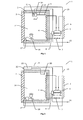
- cooling apparatus 1 (such as food/drinks coolers, refrigerators and freezers) usually comprise an outer housing 13 enclosing a cooled zone 14 enclosed by insulating wall 2 and door 3.
- the figure illustrates a gas/compressor cooling mechanism by way of example but other cooling mechanisms are known and in common use.
- cooling effect is provided by a gas/liquid circuit comprising motorcompressor 6, condenser 5, expansion restriction 7 and evaporator 4.
- Heat is taken from the cooled zone by evaporator 4 and heat is rejected to the environment (e.g. air around the apparatus) from condenser 5.
- Thermoelectric control 8 on the side of the motorcompressor 6 manages the starting and overload protection for the compressor.
- Thermostatic switch 16 typically comprises sensor bulb 9 connecting to switch 10 via capillary 12.
- Switch 10 usually is provided with user control 11 which can be adjusted to change threshold temperatures of the switch so the nominal temperature of the cooled zone can be set as desired.
- Power to the motorcompressor is controlled by the thermostatic switch. The switch closes to start the motorcompressor when the temperature sensed by the bulb 9 rises above a higher threshold temperature and then opens to stop the motorcompressor when the temperature sensed by the bulb falls below a lower threshold temperature.
- the thermostatic switch, including sensor bulb etc. have to be constructed to be resistant to the environment of the cooled zone. In particular they must be resistant to moisture and, because the switch is accessible in the cooled zone, the electrical parts have to be robustly insulated to avoid risk of electrical shock to any user.
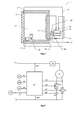
- FIG. 2 shows an alternative thermostat arrangement, using an electronic sensor (20) located in the cooled zone. It connects to an electronic circuit 21 which responds to the sensor and connects or disconnects power to the motorcompressor 6 according to the rise and fall of the temperature sensed by sensor 20 in a similar way to that of the electromechanical thermostatic switch 16 described previously.
- the electronic circuit may be provided with a user control 22 to adjust the switching threshold temperatures to control the nominal temperature of the cooled zone.
- the electronic circuit 21 is located outside the cooled zone (but inside the outer housing 2) because the environmental characteristics of the cooled zone reduce the reliability of the circuit and power dissipation in the circuit causes unwanted heating in the cooled zone.
- Sensor 20 which is usually a thermistor but could be some other temperature sensitive device (e.g.
- thermocouple temperature-sensitive resistor or semiconductor junction
- the electronic circuit 21 and sensor 20 often operate at hazardous voltages so it is necessary to provide strong insulation to avoid risk of electrical shock to users. This is particularly important for sensor 20 because it is exposed in the accessible cooled zone and may be covered in condensation or ice which can act as an electrical path through very small gaps in any enclosure of the sensor.
- the advantages of using an electronic temperature control system are that finer and/or more accurate temperature control is possible and other user benefits can be provided (e.g. display of temperature of the cooled zone).
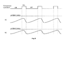
- FIG. 3a shows a time profile of temperature in comparison to upper threshold temperature 24 and lower threshold temperature 23.
- Figure 3b shows the on/off control of the cooling mechanism, turning on when the sensed temperature rises above the higher threshold and turning off when it falls below the lower threshold. Note that the temperature overshoots/undershoots the threshold temperature as a result of thermal capacities and lags inherent in the system.
- Figure 4 shows a switching cycle where the thermal conditions require more cooling effect e.g. as a result of higher ambient temperature around the apparatus, or warm items placed in the cooled zone. Because of the larger amount of heat applied to the cooled zone, its temperature rises more quickly when the cooling mechanism is not running. When the mechanism is running, the temperature falls, but more slowly than shown in Figure 3 because the net rate of heat removal is lower because the increased rate heat applied to the zone balances more of the rate at which the cooling mechanism removes heat. The consequence is that the off-period is shorter and the on-period longer. So, the increased rate of heat applied to the cooled zone affects the on- and off-periods and, particularly, the proportion of overall time that the cooling mechanism is running.
- This "proportion” is a means to adjust the overall cooling effect. 100% would be maximum effect, with the cooling operating all of the time, and 0% would be no cooling effect, with no cooling effect.
- the cooling effect (average heat removal rate) is not linearly related to the proportion of time running. When a cooling mechanism is started, it takes some time to establish a temperature differential, and if it is stopped early then the cooling effect is disproportionately small. At high levels of cooling rate, increased temperature differences develop (e.g. between the evaporator and the cooled zone, and between the condenser and the external environment). Increased temperature differences usually cause a reduction of heat pumped by the cooling mechanism. Between these extremes of duty, the cooling effect will be proportionally higher.
- a first test is performed on an example of the design to find an on/off control pattern that gives a desired temperature in the cooled zone under particular conditions of external ambient temperature and mains supply voltage. We will refer to this as the "base condition”. Then, a series of tests are performed on an example of the design under a predetermined set of ambient temperatures and a predetermined set of mains voltages to find on/off patterns for each condition that gives the same desired temperature of the cooled zone. These patterns will be different from the base condition so that the cooling effect matches the different rates of heat applied to the cooled zone.
- the patterns are changed in a predetermined way in response to a "cooling effect parameter", for example as shown in Figure 5 .
- Curve Ton represents the duration of the on-period of the cooling mechanism and curve Tcycle represents the sum of Ton and Toff (the duration of the off-period).
- Ton decreases and Toff increases from zero to reduce the cooling effect.
- Ton is held at a minimum value but Toff is increased more quickly to reduce the cooling effect. So, if this "control law" is used in the series of tests, in each condition it is necessary to change only the cooling effect parameter to set a pattern that gives the desired temperature.
- the relationship between external ambient temperature and necessary cooling effect parameter will be progressive, higher ambient will progressively require a higher parameter value. From the results of the tests, this relationship can be characterised mathematically.
- the relationship between mains voltage and required parameter can be characterised mathematically. There could be some interaction between ambient temperature and mains voltage; if the ambient temperature is higher then the sensitivity to mains voltage may be increased. This can also be characterised by a more sophisticated mathematical model, yielding the necessary cooling effect parameter from both the mains voltage variable and the ambient temperature variable.
- a convenient mathematical model is to hold a series of combinations (points) of mains voltage, ambient temperature and necessary cooling effect parameter. In a new situation, the necessary cooling effect parameter is found from the prevailing mains voltage and ambient temperature conditions by interpolating between nearby points in the series.
- Described here is a method to control temperature of the cooled zone, compensating for the effects of mains voltage and ambient temperature. Clearly it would be possible to control only on the basis of one of these (for example, only mains voltage) in which case changes other would not be taken into account and could cause larger deviations of the cooled zone temperature from the desired temperature.
- a time variation of the cooling effect parameter may be found that counteracts the increase in temperature to minimise the disturbance of temperature.
- the effect of opening the door can, of course, be variable as a result of different duration for which the door is open and different external ambient temperature.
- These effects can be characterised in more sophisticated tests on an example apparatus by testing the effect of door openings of different durations, and under conditions of different external ambient temperature. More particularly, the necessary time variation of cooling effect parameter to counteract the temperature deviation can be found for different combinations of door open time and external ambient temperature.
- short-term deviations as a result of opening the door can be managed according to a mathematical model of the necessary time variation of cooling effect parameter - based on door open time and/or external ambient temperature.
- a higher heat load applied to the cooled zone will result in more significant changes to the sensed temperature profile.
- the effect on the time profile is not large, but the profile of the sensed gas flow temperature can be examined to detect a change which indicates that a higher heat load has been applied. Further, the detection can also take into account other factors such as:
- a decision about whether or not an additional heat load has been placed in the cooled zone can include weightings according to the degree of the above factors in addition to a degree of change of the gas temperature profile. The result is to decide whether or not a heat load has been applied, if it is decided that it has then a short-term increase of cooling parameter effect can be triggered.
- a series of tests can be conducted on an example cooling apparatus where typical heat loads are placed in the cooled zone and time profiles of parameter increase are found to counteract increase of temperature of the zone.
- a further sophistication can be to deduce an estimate of the degree of heat load from the degree of change of the sensed gas temperature profile.
- the degree of change is used to select an appropriate time profile of increased cooling effect parameter.
- the appropriate profiles can be characterised from tests on an example apparatus, being subjected to a range of increased heat loads.
- the change in gas conditions increases the load on the compressor and this is reflected in the electrical conditions of the motor.
- the current taken by the main winding increases and more particularly the power taken (i.e. including the effect of relative phase between voltage and current) increases.
- the voltage induced in an auxiliary winding is also affected by the additional load, typically showing as a reduction of amplitude and/or change of phase.
- Temperature of the cooled zone is affected by many variables, including those described above (external ambient temperature, mains voltage, door opening etc.). Other variables are associated with the particular example of the cooling apparatus, such as:
- the temperature management is based on the characteristics of one example of a design then tolerances of other examples of the design could result in variation to temperature of the cooled zone. These can be corrected (wholly or partly) by one or more adjustments of each example.
- an example of a design can be tested an characterised in an extensive series of tests. Then this characterisation can be applied as a base characterisation to individual examples. These can then be tested in a further, reduced series of tests or even a single test and adjustment(s) made to correct for the small differences of each example from the base characterisation.
- each example apparatus is operated in a steady state at a particular mains voltage. The average temperature in the cooled zone is measured and a calculation performed on it, optionally also including the prevailing ambient temperature, to devise an improved control law which can then be applied to the example apparatus.
- thermal control 25 optionally includes facilities to:
- FIG. 7 is a diagrammatic representation of thermal control 25, applied to the example of a cooling mechanism using a motorcompressor (but could be applied to other types of cooling mechanisms). Electrical power from supply connections 31 and 32 is applied to the Motor 27 of the motorcompressor and controlled by one or more switches such as 29 and 30, for example for "main” and “auxiliary” windings of induction motors commonly used for small cooling apparatus.
- Thermal control 25 may also include thermoelectric overload protector 28 and other components associated with starting and running the motor (e.g. run capacitor and starting PTC (a thermistor with a positive temperature coefficient) - not shown in Figure 7 ). Switch(es) to control the motor are operated by electronic circuit 33 which optionally has:
- the ambient temperature sensor 26 is most economically integrated with the control 25 but if this is adjacent to a motorcompressor or other heated/cooled parts it may give less effective control of the temperature of the cooled zone.
- the sensor is located a small distance from such parts, either by separation from the control 25 or by shaping of the housing of the control with the sensor located at an extremity.
- the control 25 may be located in the cooling apparatus away from heated/cooled parts.
- the user control 38 can be integrated with the control 25 but this may be inconvenient to users.
- it may be put in a more convenient location (eg. Like control 22 in Figure 2 ), connecting to the control 25 by a cable.
- the entire control 25 may be located more conveniently, such as for control 21 in Figure 2 .
- an ambient temperature sensor could be integrated with the control without adverse sensing effects from any nearby hot/cold parts.
- such a location can be selected to reduce the incidence of humidity which can cause degradation and fault in the control.
- Circuit 33 which may be embodied as a microcontroller and/or discrete components and/or dedicated analog/digital integrated circuits provides a control characteristic according to any of the characteristics described previously, responding to inputs provided in the particular embodiment. For example:
- control 25 A particular requirement for refrigerators and coolers is to avoid accumulation of ice on the evaporator in the cooled zone.
- the temperature of the evaporator may not rise above the melting point of ice.
- a feature is included in the control circuit 33 that detects the condition of high duty (e.g. over 30%) over a long period (e.g. longer than 12 or 24 hours). If this condition is detected the control preferably responds by stopping the cooling mechanism for a preset time, sufficient to ensure that the ice melts and the water runs to waste. A time such as 30 minutes may be sufficient but this can be characterised from tests on an example of the design of apparatus.
- control 25 preferably stops the cooling mechanism for a time that varies inversely with the sensed ambient temperature because this assures melting of the ice but reduces the deviation of temperature of the cooled zone.
- the appropriate stop-time/ambient temperature characteristic is taken from the tests of an example apparatus.
Landscapes
- Engineering & Computer Science (AREA)
- Chemical & Material Sciences (AREA)
- Combustion & Propulsion (AREA)
- Physics & Mathematics (AREA)
- Mechanical Engineering (AREA)
- Thermal Sciences (AREA)
- General Engineering & Computer Science (AREA)
- Devices That Are Associated With Refrigeration Equipment (AREA)
Applications Claiming Priority (1)
| Application Number | Priority Date | Filing Date | Title |
|---|---|---|---|
| GBGB1100210.2A GB201100210D0 (en) | 2011-01-07 | 2011-01-07 | Temperature control systems |
Publications (2)
| Publication Number | Publication Date |
|---|---|
| EP2474799A2 true EP2474799A2 (fr) | 2012-07-11 |
| EP2474799A3 EP2474799A3 (fr) | 2012-10-31 |
Family
ID=43663898
Family Applications (1)
| Application Number | Title | Priority Date | Filing Date |
|---|---|---|---|
| EP12150133A Withdrawn EP2474799A3 (fr) | 2011-01-07 | 2012-01-04 | Systèmes de contrôle de la température |
Country Status (2)
| Country | Link |
|---|---|
| EP (1) | EP2474799A3 (fr) |
| GB (1) | GB201100210D0 (fr) |
Cited By (4)
| Publication number | Priority date | Publication date | Assignee | Title |
|---|---|---|---|---|
| ITMI20121677A1 (it) * | 2012-10-08 | 2014-04-09 | Dixell S R L Societa Unipersonale | Sistema di controllo per apparati e sistemi refrigerati con avanzate funzioni di risparmio energetico |
| EP2733449A3 (fr) * | 2012-11-16 | 2016-06-22 | Electrolux Home Products Corporation N.V. | Appareil ménager avec système de détection d'une condition ambiante |
| CN108444203A (zh) * | 2018-03-30 | 2018-08-24 | 中铁第四勘察设计院集团有限公司 | 一种冷库温度同步监控系统及调节方法 |
| CN115390641A (zh) * | 2022-08-22 | 2022-11-25 | 紫光计算机科技有限公司 | 冷却装置的控制方法、装置、电子设备及存储介质 |
Family Cites Families (2)
| Publication number | Priority date | Publication date | Assignee | Title |
|---|---|---|---|---|
| IT1245076B (it) * | 1991-04-18 | 1994-09-13 | Merloni Elettrodomestici Spa | Frigorifero |
| DE102006040370A1 (de) * | 2006-08-29 | 2008-03-06 | BSH Bosch und Siemens Hausgeräte GmbH | Kältegerät mit zwangsbelüftetem Verdampfer |
-
2011
- 2011-01-07 GB GBGB1100210.2A patent/GB201100210D0/en not_active Ceased
-
2012
- 2012-01-04 EP EP12150133A patent/EP2474799A3/fr not_active Withdrawn
Non-Patent Citations (1)
| Title |
|---|
| None |
Cited By (7)
| Publication number | Priority date | Publication date | Assignee | Title |
|---|---|---|---|---|
| ITMI20121677A1 (it) * | 2012-10-08 | 2014-04-09 | Dixell S R L Societa Unipersonale | Sistema di controllo per apparati e sistemi refrigerati con avanzate funzioni di risparmio energetico |
| WO2014057331A1 (fr) | 2012-10-08 | 2014-04-17 | Dixell, S.R.L. | Système de commande pour équipement réfrigéré et appareil pourvu de fonctionnalités avancées d'économie d'énergie |
| CN104969137A (zh) * | 2012-10-08 | 2015-10-07 | 迪克塞尔有限公司 | 具有先进节能特征的用于冷藏设备和装置的控制系统 |
| EP2733449A3 (fr) * | 2012-11-16 | 2016-06-22 | Electrolux Home Products Corporation N.V. | Appareil ménager avec système de détection d'une condition ambiante |
| CN108444203A (zh) * | 2018-03-30 | 2018-08-24 | 中铁第四勘察设计院集团有限公司 | 一种冷库温度同步监控系统及调节方法 |
| CN108444203B (zh) * | 2018-03-30 | 2023-05-16 | 中铁第四勘察设计院集团有限公司 | 一种冷库温度同步监控系统及调节方法 |
| CN115390641A (zh) * | 2022-08-22 | 2022-11-25 | 紫光计算机科技有限公司 | 冷却装置的控制方法、装置、电子设备及存储介质 |
Also Published As
| Publication number | Publication date |
|---|---|
| EP2474799A3 (fr) | 2012-10-31 |
| GB201100210D0 (en) | 2011-02-23 |
Similar Documents
| Publication | Publication Date | Title |
|---|---|---|
| US4843833A (en) | Appliance control system | |
| US6851270B2 (en) | Integrated refrigeration control | |
| US4916912A (en) | Heat pump with adaptive frost determination function | |
| CA1114038A (fr) | Systeme et methode de commande a la demande du degivrage d'appareils de refrigeration | |
| JP3712938B2 (ja) | マルチポイントデジタル温度制御装置 | |
| AU655696B2 (en) | Compressor crankcase heater control | |
| US8309894B2 (en) | Triac control of positive temperature coefficient (PTC) heaters in room air conditioners | |
| EP3447896B1 (fr) | Systèmes de commande de moteur | |
| US3939666A (en) | Stile and mullion heater control | |
| EP2474799A2 (fr) | Systèmes de contrôle de la température | |
| JPS58145867A (ja) | 冷蔵装置用温度感知装置 | |
| JPWO2017056212A1 (ja) | 冷蔵庫 | |
| EP0484860A1 (fr) | Appareil frigorifique à dispositif thermostatique unique de régulation de température | |
| US11493260B1 (en) | Freezers and operating methods using adaptive defrost | |
| EP0045728A2 (fr) | Régulateur électronique de température pour un réfrigérateur | |
| US9273889B2 (en) | Monitoring and control system for a heat pump | |
| US7665317B2 (en) | Method for controlling a refrigeration appliance | |
| JP6972310B2 (ja) | 冷凍冷蔵庫 | |
| US10429863B2 (en) | Systems and methods for refrigerator control | |
| KR100364777B1 (ko) | 냉장고 | |
| BRPI0903376A2 (pt) | controlador eletrânico multifuncional para refrigeradores e mÉtodo de realizaÇço do mesmo | |
| GB2523686A (en) | Refrigerator having a refrigeration compartment | |
| KR100364774B1 (ko) | 냉장고 | |
| KR100379458B1 (ko) | 냉장고 | |
| KR100364775B1 (ko) | 냉장고의 제어장치 및 방법 |
Legal Events
| Date | Code | Title | Description |
|---|---|---|---|
| PUAI | Public reference made under article 153(3) epc to a published international application that has entered the european phase |
Free format text: ORIGINAL CODE: 0009012 |
|
| AK | Designated contracting states |
Kind code of ref document: A2 Designated state(s): AL AT BE BG CH CY CZ DE DK EE ES FI FR GB GR HR HU IE IS IT LI LT LU LV MC MK MT NL NO PL PT RO RS SE SI SK SM TR |
|
| AX | Request for extension of the european patent |
Extension state: BA ME |
|
| RIC1 | Information provided on ipc code assigned before grant |
Ipc: F25D 29/00 20060101AFI20120629BHEP |
|
| PUAL | Search report despatched |
Free format text: ORIGINAL CODE: 0009013 |
|
| AK | Designated contracting states |
Kind code of ref document: A3 Designated state(s): AL AT BE BG CH CY CZ DE DK EE ES FI FR GB GR HR HU IE IS IT LI LT LU LV MC MK MT NL NO PL PT RO RS SE SI SK SM TR |
|
| AX | Request for extension of the european patent |
Extension state: BA ME |
|
| RIC1 | Information provided on ipc code assigned before grant |
Ipc: F25D 29/00 20060101AFI20120924BHEP |
|
| 17P | Request for examination filed |
Effective date: 20130426 |
|
| 17Q | First examination report despatched |
Effective date: 20190524 |
|
| STAA | Information on the status of an ep patent application or granted ep patent |
Free format text: STATUS: THE APPLICATION IS DEEMED TO BE WITHDRAWN |
|
| 18D | Application deemed to be withdrawn |
Effective date: 20191005 |