EP2474820B1 - Capteur de pression avec conditionnement à bas coût - Google Patents
Capteur de pression avec conditionnement à bas coût Download PDFInfo
- Publication number
- EP2474820B1 EP2474820B1 EP12150336.1A EP12150336A EP2474820B1 EP 2474820 B1 EP2474820 B1 EP 2474820B1 EP 12150336 A EP12150336 A EP 12150336A EP 2474820 B1 EP2474820 B1 EP 2474820B1
- Authority
- EP
- European Patent Office
- Prior art keywords
- pressure
- sensing
- die
- pressure port
- pressure sensing
- Prior art date
- Legal status (The legal status is an assumption and is not a legal conclusion. Google has not performed a legal analysis and makes no representation as to the accuracy of the status listed.)
- Active
Links
Images


Classifications
-
- G—PHYSICS
- G01—MEASURING; TESTING
- G01L—MEASURING FORCE, STRESS, TORQUE, WORK, MECHANICAL POWER, MECHANICAL EFFICIENCY, OR FLUID PRESSURE
- G01L9/00—Measuring steady of quasi-steady pressure of fluid or fluent solid material by electric or magnetic pressure-sensitive elements; Transmitting or indicating the displacement of mechanical pressure-sensitive elements, used to measure the steady or quasi-steady pressure of a fluid or fluent solid material, by electric or magnetic means
- G01L9/0041—Transmitting or indicating the displacement of flexible diaphragms
- G01L9/0051—Transmitting or indicating the displacement of flexible diaphragms using variations in ohmic resistance
- G01L9/0052—Transmitting or indicating the displacement of flexible diaphragms using variations in ohmic resistance of piezoresistive elements
-
- G—PHYSICS
- G01—MEASURING; TESTING
- G01L—MEASURING FORCE, STRESS, TORQUE, WORK, MECHANICAL POWER, MECHANICAL EFFICIENCY, OR FLUID PRESSURE
- G01L19/00—Details of, or accessories for, apparatus for measuring steady or quasi-steady pressure of a fluent medium insofar as such details or accessories are not special to particular types of pressure gauges
- G01L19/0061—Electrical connection means
-
- G—PHYSICS
- G01—MEASURING; TESTING
- G01L—MEASURING FORCE, STRESS, TORQUE, WORK, MECHANICAL POWER, MECHANICAL EFFICIENCY, OR FLUID PRESSURE
- G01L19/00—Details of, or accessories for, apparatus for measuring steady or quasi-steady pressure of a fluent medium insofar as such details or accessories are not special to particular types of pressure gauges
- G01L19/0007—Fluidic connecting means
- G01L19/0038—Fluidic connecting means being part of the housing
-
- G—PHYSICS
- G01—MEASURING; TESTING
- G01L—MEASURING FORCE, STRESS, TORQUE, WORK, MECHANICAL POWER, MECHANICAL EFFICIENCY, OR FLUID PRESSURE
- G01L19/00—Details of, or accessories for, apparatus for measuring steady or quasi-steady pressure of a fluent medium insofar as such details or accessories are not special to particular types of pressure gauges
- G01L19/0061—Electrical connection means
- G01L19/0069—Electrical connection means from the sensor to its support
-
- G—PHYSICS
- G01—MEASURING; TESTING
- G01L—MEASURING FORCE, STRESS, TORQUE, WORK, MECHANICAL POWER, MECHANICAL EFFICIENCY, OR FLUID PRESSURE
- G01L19/00—Details of, or accessories for, apparatus for measuring steady or quasi-steady pressure of a fluent medium insofar as such details or accessories are not special to particular types of pressure gauges
- G01L19/0061—Electrical connection means
- G01L19/0084—Electrical connection means to the outside of the housing
-
- G—PHYSICS
- G01—MEASURING; TESTING
- G01L—MEASURING FORCE, STRESS, TORQUE, WORK, MECHANICAL POWER, MECHANICAL EFFICIENCY, OR FLUID PRESSURE
- G01L19/00—Details of, or accessories for, apparatus for measuring steady or quasi-steady pressure of a fluent medium insofar as such details or accessories are not special to particular types of pressure gauges
- G01L19/14—Housings
-
- G—PHYSICS
- G01—MEASURING; TESTING
- G01L—MEASURING FORCE, STRESS, TORQUE, WORK, MECHANICAL POWER, MECHANICAL EFFICIENCY, OR FLUID PRESSURE
- G01L9/00—Measuring steady of quasi-steady pressure of fluid or fluent solid material by electric or magnetic pressure-sensitive elements; Transmitting or indicating the displacement of mechanical pressure-sensitive elements, used to measure the steady or quasi-steady pressure of a fluid or fluent solid material, by electric or magnetic means
- G01L9/0041—Transmitting or indicating the displacement of flexible diaphragms
- G01L9/0051—Transmitting or indicating the displacement of flexible diaphragms using variations in ohmic resistance
- G01L9/0052—Transmitting or indicating the displacement of flexible diaphragms using variations in ohmic resistance of piezoresistive elements
- G01L9/0054—Transmitting or indicating the displacement of flexible diaphragms using variations in ohmic resistance of piezoresistive elements integral with a semiconducting diaphragm
Definitions
- the present disclosure relates generally to pressure sensors, and more particularly, to pressure sensors with low cost packaging.
- Pressure sensors are used in a wide variety of applications including, for example, commercial, automotive, aerospace, industrial, and medical applications.
- pressure sensors may detect a pressure via a sensing element, often formed on a pressure sensing die, which converts mechanical stress caused by an incoming pressure into an electrical output signal.
- it may be desirable to reduce the cost of the pressure sensor as much as possible.
- a pressure sensor comprising the features of the preamble of claim 1 is disclosed in patent documents EP0553725 and JP2000199725 .
- a pressure sensor assembly may include a pressure sensing die having a front side and a back side.
- the pressure sensing die may further include a pressure sensing diaphragm having one or more piezoresistors coupled to the pressure sensing diaphragm for sensing a pressure induced stress in the pressure sensing diaphragm.
- Two or more electrical bond pads may be positioned on the front side of the pressure sensor die, with each of the two or more electrical bond pads electrically coupled to one or more of the piezoresistors.
- the pressure sensor assembly may further include a housing having a mounting side and a sensing side.
- the sensing side may define a pressure port.
- the pressure sensor die may be secured to the housing such that the back side of the pressure sensor die faces the sensing side of the housing with the pressure sensing diaphragm exposed to the pressure port.
- the front side of the pressure sensing die may be positioned adjacent to the mounting side of the housing with the two or more electrical bond pads of the pressure sensing die being accessible from outside of the housing.
- the pressure port may include an elongated pressure port.
- fluid is not intended to be limited to a liquid media. Rather the term “fluid” is considered as including any material subject to flow, such as, but not limited to, liquids and gases.
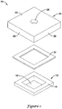
- FIG 1 is an exploded perspective top view of an illustrative pressure sensor assembly 10.
- the pressure sensor assembly 10 may include a porting housing 20 configured to provide a fluid connection between a pressure sensing die 12 and a customer application.
- the housing 20 may be formed from plastic, polyamide, ceramic, metal, or any other suitable material. While the housing 20 is illustrated as having a generally square shape, it is contemplated the housing 20 may have any shape desired.
- the housing 20 may include a top side 23 and a bottom side 25 (shown better in Figure 2 ). In some instances, the housing 20 may include a pressure port 26 extending from the top side 23 to the bottom side 25.
- the pressure port 26 may be configured to allow fluid communication between an application and the pressure sensing die 12 of the pressure sensor assembly 10.
- the pressure port 26 is illustrated as including a circular aperture, it is contemplated that the pressure port 26 may be adapted to include a variety of interface options and connections, as desired.
- the pressure port 26 may include any shape or size as desired, often depending on the particular application at hand.
- the housing 20 may not include a port 26. When so provided, the housing 20, in conjunction with the back side of the pressure sensing die, may form an enclosed cavity for containing a reference pressure.
- the pressure sensing die 12 may be a micromechanical sensor element fabricated using a silicon wafer and suitable fabrication techniques.
- the pressure sensing die 12 may include one or more pressure sensing elements and/or other circuitry (e.g. trim circuitry, signal conditioning circuitry, etc.) formed using suitable fabrication or printing techniques.
- the pressure sensing die 12 may include a pressure sensing diaphragm 18 including one or more sensing elements, such as piezoresistive sensing components, formed thereon for sensing a deflection and thus a pressure differential between a top and bottom side of the pressure sensing diaphragm 18.
- the piezoresistors may be configured in such a manner that their resistance changes in response to the flexing of the pressure sensing diaphragm 18.
- the pressure sensing diaphragm 18 may include a piezoresistive Wheatstone bridge built into a micro-machined silicon diaphragm structure.
- the pressure output of the pressure sensor assembly 10 may correspond to the changes in the resistance of the piezoresistors.
- the pressure sensing diaphragm 18 may be fabricated by back-side etching a silicon die, however, any suitable process may be used, as desired.
- the pressure sensing die 12 may include a back side 16 and an opposing front side 14 (better shown in Figure 2 ).
- the back side 16 of the sensing die 12 may be bonded to the housing 20 using an adhesive, seal, gasket, or any other suitable bonding or sealing mechanism 32 (e.g. solder, eutectic, etc.).
- the pressure sensing die 12 may be attached to the housing 20 using a stress isolating adhesive, such as, but not limited to, a silicone room temperature vulcanizing (RTV) adhesive.
- the seal 32 may be configured to attach the sensing die 12 to the housing 20 while allowing the pressure sensing diaphragm 18 to be exposed to the pressure port 26 defined by the housing 20.
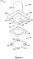
- FIG 2 illustrates an exploded perspective bottom view of the illustrative pressure sensor 10 of Figure 1 .
- the bottom side 25 of the housing 20 may include a mounting side surface 22 and a sensing side surface 24.
- the mounting side 22 is connected to but spaced back from the sensing side 24 by one or more lateral side walls 28.
- the mounting side 22 may define an opening such that the sensing side 24 and the side walls 28, together define a pressure sensing die cavity 34.
- the pressure sensing die 12 may be mounted within the die cavity 34 such that the back side 16 of the pressure sensing die 12 is facing and/or attached to an inside surface of the sensing side 24 of the housing 20.
- the sensing side 24 of the housing 20 may define a wall including the pressure port 26 such that when the pressure sensing die 12 is mounted within the die cavity 34, the pressure port 26 is in fluid communication with the pressure sensing diaphragm 18.
- a seal 32, layer of adhesive, gasket, or other sealing mechanism may be disposed between the sensing side 24 of the housing 20 and the back side 16 of the pressure sensing die 12 to secure the die 12 within the die cavity 34.
- the front side 14 of the pressure sense die 12 may be positioned adjacent to (at, below, or above) the mounting side 22 of the housing 20.
- the pressure sensing die 12 may include one or more electrical bond pads 30 disposed on the front side 14 of the die 12.
- the electrical bond pads 30 may be positioned such that the pads 30 are accessible from outside of the housing 20.
- the electrical bond pads 30 may be electrically coupled to the one or more sensing elements of the pressure sensing diaphragm 18.
- the pressure sensing die 12 may include four electrical bond pads 30, each connected to one of the four connections of a Wheatstone bridge that includes the sensing piezoresistors.
- the pressure sensing die 12 may include any number of electrical bond pads 30, as desired.
- the electrical bond pads 30 may be 0.7 millimeters by 0.3 millimeters, or any other suitable size.
- the electrical bond pads 30 may be relatively small with bump pads attached thereto such that the pressure sensor 10 may be attached to a special interface or PCB.
- the electrical bond pads 30 extend out past the mounting side 22 of the housing 20.
- Figure 3 is a perspective view of the assembled pressure sensor 10 of Figure 2 .
- the pressure sensing die 12 may be sized and shaped to generally correspond to the size and shape of the pressure sensing die cavity 34 of the housing 20.
- the front side 14 of the pressure sensing die 12 may be adjacent to, or positioned generally near the mounting side 22 of the housing 20.
- the front side 14 of the pressure sensing die 12 may be recessed within the die cavity 34 or may extend out beyond the mounting side 22 of the housing 20.
- the pressure sensing die 12 is positioned such that the electrical bond pads 30 are exposed, and is suitable for soldering directly to corresponding bond pads on a PCB or other substrate.
- the pressure sensing die 12 is positioned within the die cavity 34 such that the pressure sensing diaphragm 18 is in fluid communication with the pressure port 26.
- the pressure sensing diaphragm 18 may be free to flex such that the one or more pressure sensing elements may sense a deflection and thus a pressure differential between a top and bottom side of the pressure sensing diaphragm 18.
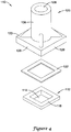
- FIG 4 is an exploded perspective top view of another illustrative pressure sensor assembly 110.
- the pressure sensor assembly 110 may include a porting housing 120 configured to provide a fluid connection between a pressure sensing die 112 and a customer application.
- the housing 120 may be formed from plastic, polyamide, ceramic, metal, or any other suitable material. While the housing 120 is illustrated as having a generally square shape, it is contemplated the housing 120 may have any shape desired.
- the housing 120 may include a top side 123 and a bottom side 125 (better shown in Figure 5 ). In some instances, the housing 120 may include a pressure port 126 extending between the top side 123 to the bottom side 125.
- the pressure port 126 may be configured to allow fluid communication between an application and the pressure sensing die 112 of the pressure sensor assembly 110.
- the pressure port 126 may be an elongated structure 136.
- the elongated structure 136 may be a generally tubular member extending away from the top side 123 of the housing 120. It is contemplated that the pressure port 126 may include a variety of interface options and connections.
- the elongated structure 136 could include an elbow, or may take on any other desired configuration or shape.
- the pressure port 126 may include a threaded or barbed region to facilitate connection to a device. It is further contemplated that, in some embodiments, the housing 120 may not include a port 126 at all, as described above.
- the pressure sensing die 112 may be a micromechanical sensor element fabricated using a silicon wafer and suitable fabrication techniques.
- the pressure sensing die 112 may include one or more pressure sensing elements and/or other circuitry (e.g. trim circuitry, signal conditioning circuitry, etc.) formed using suitable fabrication or printing techniques.
- the pressure sensing die 112 may include a pressure sensing diaphragm 118 including one or more sensing elements, such as piezoresistive sensing components, formed thereon for sensing a deflection and thus a pressure differential between a top and bottom side of the pressure sensing diaphragm 118.
- the piezoresistors may be configured in such a manner that their resistance changes in response to the flexing of the pressure sensing diaphragm 118.
- the pressure sensing diaphragm 118 may include a piezoresistive Wheatstone bridge built into a micro-machined silicon diaphragm structure.
- the pressure output of the pressure sensor assembly 110 may correspond to changes in the resistance of the piezoresistors.
- the pressure sensing diaphragm 118 may be fabricated by back-side etching a silicon die, however, it is contemplated that any suitable process may be used, as desired.
- the pressure sensing die 112 may include a back side 116 and an opposing front side 114.
- the back side 116 of the sensing die 112 may be bonded to the housing 120 using an adhesive, gasket, seal, or any other suitable bonding or sealing mechanism 132 (e.g. solder, eutectic, etc.).
- the pressure sensing die 112 may be attached to the housing 120 using a stress isolating adhesive, such as, but not limited to a silicone room temperature vulcanizing (RTV) adhesive.
- the seal 132 may be configured to attach the sensing die 112 to the housing 120 while allowing the pressure sensing diaphragm 118 to be exposed to the pressure port 126 defined in the housing 120.
- FIG 5 is an exploded perspective bottom view of the illustrative pressure sensor 110 of Figure 4 .
- the bottom side 125 of the housing 120 may include a mounting side surface 122 and a sensing side surface 124.
- the mounting side 122 may be connected to and spaced a distance from the sensing side 124 by one or more lateral side walls 128.
- the mounting side 122 may define an opening such that the sensing side 124 and the side walls 128 define a pressure sensing die cavity 134.
- the pressure sensing die 112 is mounted within the die cavity 134 such that the back side 116 of the die 112 is facing and/or attached to an inside surface of the sensing side 124 of the housing 120.
- the sensing side 124 of the housing 120 may define a wall including the pressure port 126 such that when the pressure sensing die 112 is mounted within the die cavity 134, the pressure port 126 is in fluid communication with the pressure sensing diaphragm 118.
- a seal 132, gasket and/or layer of adhesive may be disposed between the sensing side 124 of the housing 120 and the back side 116 of the pressure sensing die 112 to secure the die 112 within the die cavity 134.
- the front side 114 of the pressure sense die 112 may be positioned adjacent to (at, below or above) the mounting side 122 of the housing 120.
- the pressure sensing die 112 may include one or more electrical bond pads 130 disposed on the front side 114 of the die 112.
- the electrical bond pads 130 may be positioned such that the bond pads 130 are accessible from outside of the housing 120.
- the electrical bond pads 130 may be electrically coupled to the one or more sensing elements of the pressure sensing diaphragm 118.
- the pressure sensing die 112 may include four electrical bond pads 130, each connected to one of the four connections of a Wheatstone bridge that includes the sensing piezoresistors.
- the pressure sensing die 112 may include any number of electrical bond pads 130, as desired.
- the electrical bond pads 130 may be 0.7 millimeters by 0.3 millimeters or any other suitable size.
- the electrical bond pads 130 may be relatively small with bump pads attached thereto such that the pressure sensor 110 may be attached to a special interface or PCB. In some cases, the electrical bond pads 130 may extend out past the mounting side 122 of the housing 120, but this is not required.
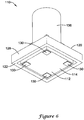
- Figure 6 is a perspective view of the assembled pressure sensor 110 of Figure 5 .
- the pressure sensing die 112 may be sized and shaped to generally correspond to the size and shape of the pressure sensing die cavity 134.
- the front side 114 of the pressure sensing die 112 may be adjacent to, or positioned generally near the mounting side 122 of the housing 120.
- the front side 114 of the pressure sensing die 112 may be recessed within the die cavity 134 or may extend beyond the mounting side 122 of the housing 120.
- the pressure sensing die 112 may be positioned such that the electrical bond pads are exposed and suitable for soldering directly to corresponding bond pads on a PCB or other substrate.
- the pressure sensing die 112 may be positioned within the die cavity 134 such that the pressure sensing diaphragm 118 is in fluid communication with the pressure port 126. When so positioned, the pressure sensing diaphragm 118 may be free to flex such that the one or more pressure sensing elements may sense a deflection and thus a pressure differential between a top and bottom side of the pressure sensing diaphragm 118.
Landscapes
- Physics & Mathematics (AREA)
- General Physics & Mathematics (AREA)
- Chemical & Material Sciences (AREA)
- Analytical Chemistry (AREA)
- Measuring Fluid Pressure (AREA)
Claims (15)
- Ensemble capteur de pression (10, 110), comprenant :un boîtier d'orifice de pression (20, 120) comportant un côté détection (24, 124) et un côté montage (22, 122), le côté détection (24, 124) comportant un orifice de pression (26, 126) s'étendant à travers le côté détection (24, 124) du boîtier d'orifice de pression (20, 120) ;le boîtier d'orifice de pression (20, 120) comportant en outre une cavité à puce de détection de pression (34, 134) ;une puce de détection de pression (12, 112) présentant un premier côté (16, 116) et un second côté opposé (14, 114), la puce de détection de pression (12, 112) étant située dans la cavité à puce de détection de pression (34, 134) son premier côté (16, 116) fixé au côté détection (24, 124) du boîtier d'orifice de pression (20, 120), la puce de détection de pression (12, 112) présentant une membrane de détection de pression (18, 118) exposée à l'orifice de pression (26, 126) ; etle second côté (14, 114) de la puce de détection de pression (12, 112) faisant dos au côté détection (24, 124) du boîtier d'orifice de pression (20, 120) et face au côté montage (22, 122)caractérisé en ce quedeux ou plusieurs plots de contact électrique (130) de la puce de capteur de pression (12, 112) s'étendent au-delà du côté montage (22, 122) et sont accessibles depuis l'extérieur du boîtier d'orifice de pression (20, 120) de telle sorte que les deux ou plusieurs plots de contact électrique (30, 130) puissent être connectés électriquement et physiquement directement à deux ou plusieurs plots de contact correspondants sur un autre substrat.
- Ensemble capteur de pression (10, 110) selon la revendication 1, comprenant en outre un joint étanche (32, 132) entre le premier côté (16, 116) de la puce de détection de pression (112) et le boîtier d'orifice de pression (120), le joint étanche (32, 132) étant configuré pour exposer la membrane de détection de pression (18, 118) de la puce de détection de pression (12, 112) à l'orifice de pression (26, 126) défini dans le côté détection (24, 124) du boîtier d'orifice de pression (120).
- Ensemble capteur de pression (10, 110) selon la revendication 1, dans lequel la puce de détection de pression (12, 112) est fixée au boîtier d'orifice de pression (20, 120) au moyen d'un adhésif.
- Ensemble capteur de pression (10, 110) selon la revendication 3, dans lequel l'adhésif (32, 132) est un adhésif de silicone à vulcanisation à température ambiante (RTV).
- Ensemble capteur de pression (10, 110) selon la revendication 1, dans lequel l'orifice de pression (26, 126) est un orifice de pression allongé (26, 126) partant d'une position adjacente au premier côté (16, 116) de la puce de détection de pression (12, 112) et s'écartant du premier côté (16, 116) de la puce de détection de pression (112) .
- Ensemble capteur de pression (10, 110) selon la revendication 5, dans lequel au moins une partie de l'orifice de pression allongé (26, 126) est de forme tubulaire.
- Ensemble capteur de pression (10, 110) selon la revendication 1, dans lequel le côté montage (22, 122) du boîtier d'orifice de pression (20, 120) est ouvert pour permettre l'insertion de la puce de détection de pression (12, 112) et sa fixation à une surface intérieure du boîtier d'orifice de pression (20, 120).
- Ensemble capteur de pression (10, 110) selon la revendication 7, dans lequel la puce de détection de pression (12, 112) est fixée à une surface intérieure du côté détection du boîtier d'orifice de pression (20, 120) .
- Ensemble capteur de pression (10, 110) selon la revendication 7, dans lequel :
le boîtier d'orifice de pression (20, 120) comporte des parois latérales (128) qui s'étendent depuis le côté détection du boîtier d'orifice de pression (120) jusqu'au côté montage. - Procédé d'utilisation d'un ensemble capteur de pression (10, 110), comprenant :la fourniture d'un ensemble capteur de pression (10, 110) comprenant :un boîtier d'orifice de pression (20, 120) comportant un côté détection (24, 124) et un côté montage (22, 122), le côté détection (24, 124) comportant un orifice de pression (26, 126) s'étendant à travers le côté détection (24, 124) du boîtier d'orifice de pression (20, 120) ;le boîtier d'orifice de pression (20, 120) comportant en outre une cavité à puce de détection de pression (34, 134) ;une puce de détection de pression (12, 112) présentant un premier côté (16, 116) et un second côté opposé (14, 114), la puce de détection de pression (12, 112) étant située dans la cavité à puce de détection de pression (34, 134) son premier côté (16, 116) fixé au côté détection (24, 124) du boîtier d'orifice de pression (20, 120), la puce de détection de pression (12, 112) présentant une membrane de détection de pression (18, 118) exposée à l'orifice de pression (26, 126) ; etle second côté (14, 114) de la puce de détection de pression (12, 112) fait dos au côté détection (24, 124) du boîtier d'orifice de pression (20, 120) et face au côté montage (22, 122), deux ou plusieurs plots de contact électrique (130) de la puce de capteur de pression (12, 112) s'étendant au-delà du côté montage (22, 122) et étant accessibles depuis l'extérieur du boîtier d'orifice de pression (20, 120) de telle sorte que les deux ou plusieurs plots de contact électrique (30, 130) puissent être connectés électriquement et physiquement directement à deux ou plusieurs plots de contact correspondants sur un autre substrat,la flexion de la membrane de détection de pression (18, 118) en réponse à un différentiel de pression entre le premier côté (16, 116) et le second côté (14, 114) de la membrane de détection de pression (18, 118) ;la détection d'une déflexion de la membrane de détection de pression (18, 118) avec un ou plusieurs éléments de détection de pression ; etla détection du différentiel de pression entre le premier côté (16, 116) et le second côté (14, 114) de la membrane de détection de pression (18, 188) en fonction de la détection de la déflexion.
- Procédé selon la revendication 10, dans lequel la puce de détection de pression (12, 112) est fixée au boîtier d'orifice de pression (20, 120) au moyen d'un adhésif.
- Procédé selon la revendication 10, dans lequel l'orifice de pression (26, 126) est un orifice de pression allongé (26, 126) partant d'une position adjacente au premier côté (16, 116) de la puce de détection de pression (12, 112) et s'écartant du premier côté (16, 116) de la puce de détection de pression (112).
- Procédé selon la revendication 12, dans lequel au moins une partie de l'orifice de pression allongé (26, 126) est de forme tubulaire.
- Procédé selon la revendication 10, dans lequel le côté montage (22, 122) du boîtier d'orifice de pression (20,120) est ouvert pour permettre l'insertion de la puce de détection de pression (12, 112) et sa fixation à une surface intérieure du boîtier d'orifice de pression (20, 120) .
- Procédé selon la revendication 14, dans lequel la puce de détection de pression (12, 112) est fixée à une surface intérieure du côté détection du boîtier d'orifice de pression (20, 120).
Applications Claiming Priority (1)
| Application Number | Priority Date | Filing Date | Title |
|---|---|---|---|
| US12/986,948 US8297127B2 (en) | 2011-01-07 | 2011-01-07 | Pressure sensor with low cost packaging |
Publications (3)
| Publication Number | Publication Date |
|---|---|
| EP2474820A2 EP2474820A2 (fr) | 2012-07-11 |
| EP2474820A3 EP2474820A3 (fr) | 2014-07-16 |
| EP2474820B1 true EP2474820B1 (fr) | 2019-11-27 |
Family
ID=45418595
Family Applications (1)
| Application Number | Title | Priority Date | Filing Date |
|---|---|---|---|
| EP12150336.1A Active EP2474820B1 (fr) | 2011-01-07 | 2012-01-05 | Capteur de pression avec conditionnement à bas coût |
Country Status (3)
| Country | Link |
|---|---|
| US (1) | US8297127B2 (fr) |
| EP (1) | EP2474820B1 (fr) |
| CN (2) | CN106370342B (fr) |
Families Citing this family (27)
| Publication number | Priority date | Publication date | Assignee | Title |
|---|---|---|---|---|
| CA2806486C (fr) * | 2011-02-07 | 2017-03-21 | The Governors Of The University Of Alberta | Capteur de charge piezoresistif |
| CN105358952B (zh) * | 2013-05-06 | 2020-01-14 | 荷语布鲁塞尔自由大学 | 有效的结构健康监测 |
| US9470593B2 (en) | 2013-09-12 | 2016-10-18 | Honeywell International Inc. | Media isolated pressure sensor |
| CN105934661B (zh) * | 2014-01-13 | 2019-11-05 | 触控解决方案股份有限公司 | 微型强化圆片级mems力传感器 |
| US9476788B2 (en) | 2014-04-22 | 2016-10-25 | Freescale Semiconductor, Inc. | Semiconductor sensor with gel filled cavity |
| US9506829B2 (en) | 2014-06-20 | 2016-11-29 | Dunan Sensing Llc | Pressure sensors having low cost, small, universal packaging |
| JP6346279B2 (ja) * | 2014-06-27 | 2018-06-20 | 北陸電気工業株式会社 | 力検出器 |
| US10107662B2 (en) | 2015-01-30 | 2018-10-23 | Honeywell International Inc. | Sensor assembly |
| DE102016003657A1 (de) | 2016-03-30 | 2017-10-05 | Hella Kgaa Hueck & Co. | Vorrichtung zum Messen eines Füllstands einer Flüssigkeit |
| US10281314B2 (en) | 2016-03-30 | 2019-05-07 | Hella Kgaa Hueck & Co. | Device for measuring a fill level of a liquid |
| DE102016003658B4 (de) * | 2016-03-30 | 2025-05-22 | HELLA GmbH & Co. KGaA | Elektronikbauteil mit einem Bauteilgehäuse |
| US9869598B1 (en) * | 2016-06-24 | 2018-01-16 | Honeywell International Inc. | Low cost small force sensor |
| EP4701393A2 (fr) | 2017-02-09 | 2026-02-25 | Nextinput, Inc. | Capteurs de force numériques intégrés et procédés de fabrication associés |
| US11243125B2 (en) | 2017-02-09 | 2022-02-08 | Nextinput, Inc. | Integrated piezoresistive and piezoelectric fusion force sensor |
| TWI627391B (zh) * | 2017-03-03 | 2018-06-21 | 智動全球股份有限公司 | 力量感測器 |
| EP3655740A4 (fr) | 2017-07-19 | 2021-07-14 | Nextinput, Inc. | Empilement de transfert de contrainte dans un capteur de force mems |
| WO2019023309A1 (fr) | 2017-07-25 | 2019-01-31 | Nextinput, Inc. | Capteur de force et d'empreintes digitales intégré |
| US11243126B2 (en) | 2017-07-27 | 2022-02-08 | Nextinput, Inc. | Wafer bonded piezoresistive and piezoelectric force sensor and related methods of manufacture |
| US11579028B2 (en) | 2017-10-17 | 2023-02-14 | Nextinput, Inc. | Temperature coefficient of offset compensation for force sensor and strain gauge |
| US11385108B2 (en) | 2017-11-02 | 2022-07-12 | Nextinput, Inc. | Sealed force sensor with etch stop layer |
| WO2019099821A1 (fr) | 2017-11-16 | 2019-05-23 | Nextinput, Inc. | Atténuateur de force pour capteur de force |
| US10837852B2 (en) * | 2017-12-29 | 2020-11-17 | Honeywell International Inc | Pressure sensor media interface with integrated seal and diaphragm |
| US11504201B2 (en) * | 2018-05-31 | 2022-11-22 | Covidien Lp | Haptic touch feedback surgical device for palpating tissue |
| US10724910B2 (en) * | 2018-07-20 | 2020-07-28 | Honeywell International Inc. | Miniature size force sensor with multiple coupling technology |
| US10962427B2 (en) | 2019-01-10 | 2021-03-30 | Nextinput, Inc. | Slotted MEMS force sensor |
| US11156521B2 (en) * | 2019-04-05 | 2021-10-26 | Honeywell International Inc. | Pressure sensor with multiple pressure sensing elements |
| CN111879455B (zh) * | 2020-07-24 | 2022-02-11 | 重庆火后草科技有限公司 | 用于床的压力传感器 |
Citations (1)
| Publication number | Priority date | Publication date | Assignee | Title |
|---|---|---|---|---|
| JPH11230846A (ja) * | 1998-02-09 | 1999-08-27 | Denso Corp | 半導体力学量センサの製造方法 |
Family Cites Families (22)
| Publication number | Priority date | Publication date | Assignee | Title |
|---|---|---|---|---|
| US4763098A (en) | 1985-04-08 | 1988-08-09 | Honeywell Inc. | Flip-chip pressure transducer |
| US4864724A (en) | 1988-05-16 | 1989-09-12 | Siemens-Bendix Automotive Electronics L.P. | Planar mounting of silicon micromachined sensors for pressure and fluid-flow measurement |
| US5285690A (en) * | 1992-01-24 | 1994-02-15 | The Foxboro Company | Pressure sensor having a laminated substrate |
| US5753820A (en) * | 1996-10-25 | 1998-05-19 | Arthur D. Little, Inc. | Fluid pressure sensing unit incorporating diaphragm deflection sensing array |
| US5945605A (en) | 1997-11-19 | 1999-08-31 | Sensym, Inc. | Sensor assembly with sensor boss mounted on substrate |
| US6351996B1 (en) | 1998-11-12 | 2002-03-05 | Maxim Integrated Products, Inc. | Hermetic packaging for semiconductor pressure sensors |
| JP4199867B2 (ja) * | 1999-01-06 | 2008-12-24 | 北陸電気工業株式会社 | 半導体圧力センサ装置 |
| US6845664B1 (en) | 2002-10-03 | 2005-01-25 | The United States Of America As Represented By The Administrator Of National Aeronautics And Space Administration | MEMS direct chip attach packaging methodologies and apparatuses for harsh environments |
| US7024937B2 (en) * | 2003-12-03 | 2006-04-11 | Honeywell International Inc. | Isolated pressure transducer |
| US7028551B2 (en) | 2004-06-18 | 2006-04-18 | Kavlico Corporation | Linearity semi-conductive pressure sensor |
| DE102005017853A1 (de) * | 2005-04-18 | 2006-10-19 | Siemens Ag | Drucksensorvorrichtung |
| CN2859488Y (zh) * | 2005-09-29 | 2007-01-17 | 新晨科技股份有限公司 | 一种压力传感器 |
| US7597005B2 (en) | 2005-11-10 | 2009-10-06 | Honeywell International Inc. | Pressure sensor housing and configuration |
| US7162927B1 (en) * | 2005-12-16 | 2007-01-16 | Honeywell International Inc. | Design of a wet/wet amplified differential pressure sensor based on silicon piezoresistive technology |
| US7266999B2 (en) * | 2006-01-30 | 2007-09-11 | Honeywell International Inc. | Thick film technology based ultra high pressure sensor utilizing integral port and diaphragm construction |
| US7930944B2 (en) | 2008-05-14 | 2011-04-26 | Honeywell International Inc. | ASIC compensated pressure sensor with soldered sense die attach |
| US7591186B1 (en) * | 2008-05-15 | 2009-09-22 | Honeywell International Inc. | Conductive seals and method for fabricating the same |
| US8297125B2 (en) * | 2008-05-23 | 2012-10-30 | Honeywell International Inc. | Media isolated differential pressure sensor with cap |
| US7900521B2 (en) * | 2009-02-10 | 2011-03-08 | Freescale Semiconductor, Inc. | Exposed pad backside pressure sensor package |
| US8322225B2 (en) * | 2009-07-10 | 2012-12-04 | Honeywell International Inc. | Sensor package assembly having an unconstrained sense die |
| US7997142B2 (en) * | 2009-07-31 | 2011-08-16 | Continental Automotive Systems, Inc. | Low pressure sensor device with high accuracy and high sensitivity |
| US8191423B2 (en) * | 2010-03-29 | 2012-06-05 | Continental Automotive Systems, Inc. | Grooved structure for die-mount and media sealing |
-
2011
- 2011-01-07 US US12/986,948 patent/US8297127B2/en not_active Expired - Fee Related
-
2012
- 2012-01-05 EP EP12150336.1A patent/EP2474820B1/fr active Active
- 2012-01-06 CN CN201610801431.7A patent/CN106370342B/zh not_active Expired - Fee Related
- 2012-01-06 CN CN201210002830.9A patent/CN102589791B/zh not_active Expired - Fee Related
Patent Citations (1)
| Publication number | Priority date | Publication date | Assignee | Title |
|---|---|---|---|---|
| JPH11230846A (ja) * | 1998-02-09 | 1999-08-27 | Denso Corp | 半導体力学量センサの製造方法 |
Also Published As
| Publication number | Publication date |
|---|---|
| CN102589791A (zh) | 2012-07-18 |
| EP2474820A3 (fr) | 2014-07-16 |
| CN106370342A (zh) | 2017-02-01 |
| US8297127B2 (en) | 2012-10-30 |
| EP2474820A2 (fr) | 2012-07-11 |
| CN106370342B (zh) | 2019-09-17 |
| US20120174680A1 (en) | 2012-07-12 |
| CN102589791B (zh) | 2016-10-05 |
Similar Documents
| Publication | Publication Date | Title |
|---|---|---|
| EP2474820B1 (fr) | Capteur de pression avec conditionnement à bas coût | |
| EP2474819B1 (fr) | Capteur de pression isolé d'un milieu | |
| US8316725B2 (en) | Force sensor | |
| US7377177B1 (en) | Pressure sensor method and apparatus | |
| EP2423656B1 (fr) | Capteur de pression | |
| EP2568270B1 (fr) | Capteur emballé avec plusieurs éléments de capteurs | |
| EP2873960B1 (fr) | Capteur de mesure de quantité physique | |
| EP2189773B1 (fr) | Design de capteur de pression différentielle liquide/liquide basé sur un procédé de conditionnement microélectronique | |
| EP2270455B1 (fr) | Appareil de détection de force | |
| EP3111182B1 (fr) | Capteur de pression differentielle | |
| JP3207123U (ja) | 媒体隔離圧力センサ | |
| EP3111184B1 (fr) | Puce de detection de pression differentielle | |
| EP2120029B1 (fr) | Capteur de pression à compensation ASIC avec fixation du puce de détection par soudage | |
| EP3538857B1 (fr) | Sous-ensemble de capteur de pression et fabrication | |
| CN101509817A (zh) | 流体压差测量装置 | |
| US9506829B2 (en) | Pressure sensors having low cost, small, universal packaging | |
| US9506831B2 (en) | Micromechanical measuring element and method for producing a micromechanical measuring element | |
| CN103837288A (zh) | 具有低热噪声的压阻式转换器 | |
| CN111751044A (zh) | 压力传感器和制造压力传感器的方法 | |
| CN114295281A (zh) | 差压传感器及其使用方法 | |
| CN101657709A (zh) | 压力传感器方法和设备 | |
| JP2018105748A (ja) | 圧力センサ | |
| CN209296205U (zh) | 压力传感器 |
Legal Events
| Date | Code | Title | Description |
|---|---|---|---|
| PUAI | Public reference made under article 153(3) epc to a published international application that has entered the european phase |
Free format text: ORIGINAL CODE: 0009012 |
|
| 17P | Request for examination filed |
Effective date: 20120105 |
|
| AK | Designated contracting states |
Kind code of ref document: A2 Designated state(s): AL AT BE BG CH CY CZ DE DK EE ES FI FR GB GR HR HU IE IS IT LI LT LU LV MC MK MT NL NO PL PT RO RS SE SI SK SM TR |
|
| AX | Request for extension of the european patent |
Extension state: BA ME |
|
| PUAL | Search report despatched |
Free format text: ORIGINAL CODE: 0009013 |
|
| AK | Designated contracting states |
Kind code of ref document: A3 Designated state(s): AL AT BE BG CH CY CZ DE DK EE ES FI FR GB GR HR HU IE IS IT LI LT LU LV MC MK MT NL NO PL PT RO RS SE SI SK SM TR |
|
| AX | Request for extension of the european patent |
Extension state: BA ME |
|
| RIC1 | Information provided on ipc code assigned before grant |
Ipc: G01L 19/00 20060101ALI20140611BHEP Ipc: G01L 19/14 20060101ALI20140611BHEP Ipc: G01L 9/00 20060101AFI20140611BHEP |
|
| 17Q | First examination report despatched |
Effective date: 20140709 |
|
| RAP1 | Party data changed (applicant data changed or rights of an application transferred) |
Owner name: HONEYWELL INTERNATIONAL INC. |
|
| GRAP | Despatch of communication of intention to grant a patent |
Free format text: ORIGINAL CODE: EPIDOSNIGR1 |
|
| STAA | Information on the status of an ep patent application or granted ep patent |
Free format text: STATUS: GRANT OF PATENT IS INTENDED |
|
| INTG | Intention to grant announced |
Effective date: 20190621 |
|
| GRAS | Grant fee paid |
Free format text: ORIGINAL CODE: EPIDOSNIGR3 |
|
| GRAA | (expected) grant |
Free format text: ORIGINAL CODE: 0009210 |
|
| STAA | Information on the status of an ep patent application or granted ep patent |
Free format text: STATUS: THE PATENT HAS BEEN GRANTED |
|
| AK | Designated contracting states |
Kind code of ref document: B1 Designated state(s): AL AT BE BG CH CY CZ DE DK EE ES FI FR GB GR HR HU IE IS IT LI LT LU LV MC MK MT NL NO PL PT RO RS SE SI SK SM TR |
|
| REG | Reference to a national code |
Ref country code: GB Ref legal event code: FG4D |
|
| REG | Reference to a national code |
Ref country code: CH Ref legal event code: EP |
|
| REG | Reference to a national code |
Ref country code: AT Ref legal event code: REF Ref document number: 1207224 Country of ref document: AT Kind code of ref document: T Effective date: 20191215 |
|
| REG | Reference to a national code |
Ref country code: DE Ref legal event code: R096 Ref document number: 602012065954 Country of ref document: DE |
|
| REG | Reference to a national code |
Ref country code: IE Ref legal event code: FG4D |
|
| REG | Reference to a national code |
Ref country code: NL Ref legal event code: MP Effective date: 20191127 |
|
| REG | Reference to a national code |
Ref country code: LT Ref legal event code: MG4D |
|
| PG25 | Lapsed in a contracting state [announced via postgrant information from national office to epo] |
Ref country code: BG Free format text: LAPSE BECAUSE OF FAILURE TO SUBMIT A TRANSLATION OF THE DESCRIPTION OR TO PAY THE FEE WITHIN THE PRESCRIBED TIME-LIMIT Effective date: 20200227 Ref country code: FI Free format text: LAPSE BECAUSE OF FAILURE TO SUBMIT A TRANSLATION OF THE DESCRIPTION OR TO PAY THE FEE WITHIN THE PRESCRIBED TIME-LIMIT Effective date: 20191127 Ref country code: LV Free format text: LAPSE BECAUSE OF FAILURE TO SUBMIT A TRANSLATION OF THE DESCRIPTION OR TO PAY THE FEE WITHIN THE PRESCRIBED TIME-LIMIT Effective date: 20191127 Ref country code: SE Free format text: LAPSE BECAUSE OF FAILURE TO SUBMIT A TRANSLATION OF THE DESCRIPTION OR TO PAY THE FEE WITHIN THE PRESCRIBED TIME-LIMIT Effective date: 20191127 Ref country code: NL Free format text: LAPSE BECAUSE OF FAILURE TO SUBMIT A TRANSLATION OF THE DESCRIPTION OR TO PAY THE FEE WITHIN THE PRESCRIBED TIME-LIMIT Effective date: 20191127 Ref country code: ES Free format text: LAPSE BECAUSE OF FAILURE TO SUBMIT A TRANSLATION OF THE DESCRIPTION OR TO PAY THE FEE WITHIN THE PRESCRIBED TIME-LIMIT Effective date: 20191127 Ref country code: LT Free format text: LAPSE BECAUSE OF FAILURE TO SUBMIT A TRANSLATION OF THE DESCRIPTION OR TO PAY THE FEE WITHIN THE PRESCRIBED TIME-LIMIT Effective date: 20191127 Ref country code: GR Free format text: LAPSE BECAUSE OF FAILURE TO SUBMIT A TRANSLATION OF THE DESCRIPTION OR TO PAY THE FEE WITHIN THE PRESCRIBED TIME-LIMIT Effective date: 20200228 Ref country code: NO Free format text: LAPSE BECAUSE OF FAILURE TO SUBMIT A TRANSLATION OF THE DESCRIPTION OR TO PAY THE FEE WITHIN THE PRESCRIBED TIME-LIMIT Effective date: 20200227 |
|
| PG25 | Lapsed in a contracting state [announced via postgrant information from national office to epo] |
Ref country code: IS Free format text: LAPSE BECAUSE OF FAILURE TO SUBMIT A TRANSLATION OF THE DESCRIPTION OR TO PAY THE FEE WITHIN THE PRESCRIBED TIME-LIMIT Effective date: 20200327 Ref country code: RS Free format text: LAPSE BECAUSE OF FAILURE TO SUBMIT A TRANSLATION OF THE DESCRIPTION OR TO PAY THE FEE WITHIN THE PRESCRIBED TIME-LIMIT Effective date: 20191127 Ref country code: HR Free format text: LAPSE BECAUSE OF FAILURE TO SUBMIT A TRANSLATION OF THE DESCRIPTION OR TO PAY THE FEE WITHIN THE PRESCRIBED TIME-LIMIT Effective date: 20191127 |
|
| PG25 | Lapsed in a contracting state [announced via postgrant information from national office to epo] |
Ref country code: AL Free format text: LAPSE BECAUSE OF FAILURE TO SUBMIT A TRANSLATION OF THE DESCRIPTION OR TO PAY THE FEE WITHIN THE PRESCRIBED TIME-LIMIT Effective date: 20191127 |
|
| PG25 | Lapsed in a contracting state [announced via postgrant information from national office to epo] |
Ref country code: RO Free format text: LAPSE BECAUSE OF FAILURE TO SUBMIT A TRANSLATION OF THE DESCRIPTION OR TO PAY THE FEE WITHIN THE PRESCRIBED TIME-LIMIT Effective date: 20191127 Ref country code: CZ Free format text: LAPSE BECAUSE OF FAILURE TO SUBMIT A TRANSLATION OF THE DESCRIPTION OR TO PAY THE FEE WITHIN THE PRESCRIBED TIME-LIMIT Effective date: 20191127 Ref country code: PT Free format text: LAPSE BECAUSE OF FAILURE TO SUBMIT A TRANSLATION OF THE DESCRIPTION OR TO PAY THE FEE WITHIN THE PRESCRIBED TIME-LIMIT Effective date: 20200419 Ref country code: EE Free format text: LAPSE BECAUSE OF FAILURE TO SUBMIT A TRANSLATION OF THE DESCRIPTION OR TO PAY THE FEE WITHIN THE PRESCRIBED TIME-LIMIT Effective date: 20191127 Ref country code: DK Free format text: LAPSE BECAUSE OF FAILURE TO SUBMIT A TRANSLATION OF THE DESCRIPTION OR TO PAY THE FEE WITHIN THE PRESCRIBED TIME-LIMIT Effective date: 20191127 |
|
| REG | Reference to a national code |
Ref country code: DE Ref legal event code: R097 Ref document number: 602012065954 Country of ref document: DE |
|
| PG25 | Lapsed in a contracting state [announced via postgrant information from national office to epo] |
Ref country code: SM Free format text: LAPSE BECAUSE OF FAILURE TO SUBMIT A TRANSLATION OF THE DESCRIPTION OR TO PAY THE FEE WITHIN THE PRESCRIBED TIME-LIMIT Effective date: 20191127 Ref country code: SK Free format text: LAPSE BECAUSE OF FAILURE TO SUBMIT A TRANSLATION OF THE DESCRIPTION OR TO PAY THE FEE WITHIN THE PRESCRIBED TIME-LIMIT Effective date: 20191127 Ref country code: MC Free format text: LAPSE BECAUSE OF FAILURE TO SUBMIT A TRANSLATION OF THE DESCRIPTION OR TO PAY THE FEE WITHIN THE PRESCRIBED TIME-LIMIT Effective date: 20191127 |
|
| REG | Reference to a national code |
Ref country code: CH Ref legal event code: PL |
|
| REG | Reference to a national code |
Ref country code: AT Ref legal event code: MK05 Ref document number: 1207224 Country of ref document: AT Kind code of ref document: T Effective date: 20191127 |
|
| PLBE | No opposition filed within time limit |
Free format text: ORIGINAL CODE: 0009261 |
|
| STAA | Information on the status of an ep patent application or granted ep patent |
Free format text: STATUS: NO OPPOSITION FILED WITHIN TIME LIMIT |
|
| REG | Reference to a national code |
Ref country code: BE Ref legal event code: MM Effective date: 20200131 |
|
| PG25 | Lapsed in a contracting state [announced via postgrant information from national office to epo] |
Ref country code: LU Free format text: LAPSE BECAUSE OF NON-PAYMENT OF DUE FEES Effective date: 20200105 |
|
| 26N | No opposition filed |
Effective date: 20200828 |
|
| PG25 | Lapsed in a contracting state [announced via postgrant information from national office to epo] |
Ref country code: AT Free format text: LAPSE BECAUSE OF FAILURE TO SUBMIT A TRANSLATION OF THE DESCRIPTION OR TO PAY THE FEE WITHIN THE PRESCRIBED TIME-LIMIT Effective date: 20191127 Ref country code: BE Free format text: LAPSE BECAUSE OF NON-PAYMENT OF DUE FEES Effective date: 20200131 Ref country code: CH Free format text: LAPSE BECAUSE OF NON-PAYMENT OF DUE FEES Effective date: 20200131 Ref country code: LI Free format text: LAPSE BECAUSE OF NON-PAYMENT OF DUE FEES Effective date: 20200131 Ref country code: PL Free format text: LAPSE BECAUSE OF FAILURE TO SUBMIT A TRANSLATION OF THE DESCRIPTION OR TO PAY THE FEE WITHIN THE PRESCRIBED TIME-LIMIT Effective date: 20191127 Ref country code: SI Free format text: LAPSE BECAUSE OF FAILURE TO SUBMIT A TRANSLATION OF THE DESCRIPTION OR TO PAY THE FEE WITHIN THE PRESCRIBED TIME-LIMIT Effective date: 20191127 |
|
| REG | Reference to a national code |
Ref country code: DE Ref legal event code: R082 Ref document number: 602012065954 Country of ref document: DE Representative=s name: HL KEMPNER PATENTANWALT, RECHTSANWALT, SOLICIT, DE |
|
| PG25 | Lapsed in a contracting state [announced via postgrant information from national office to epo] |
Ref country code: IT Free format text: LAPSE BECAUSE OF FAILURE TO SUBMIT A TRANSLATION OF THE DESCRIPTION OR TO PAY THE FEE WITHIN THE PRESCRIBED TIME-LIMIT Effective date: 20191127 Ref country code: IE Free format text: LAPSE BECAUSE OF NON-PAYMENT OF DUE FEES Effective date: 20200105 |
|
| PGFP | Annual fee paid to national office [announced via postgrant information from national office to epo] |
Ref country code: DE Payment date: 20210129 Year of fee payment: 10 |
|
| PG25 | Lapsed in a contracting state [announced via postgrant information from national office to epo] |
Ref country code: TR Free format text: LAPSE BECAUSE OF FAILURE TO SUBMIT A TRANSLATION OF THE DESCRIPTION OR TO PAY THE FEE WITHIN THE PRESCRIBED TIME-LIMIT Effective date: 20191127 Ref country code: MT Free format text: LAPSE BECAUSE OF FAILURE TO SUBMIT A TRANSLATION OF THE DESCRIPTION OR TO PAY THE FEE WITHIN THE PRESCRIBED TIME-LIMIT Effective date: 20191127 Ref country code: CY Free format text: LAPSE BECAUSE OF FAILURE TO SUBMIT A TRANSLATION OF THE DESCRIPTION OR TO PAY THE FEE WITHIN THE PRESCRIBED TIME-LIMIT Effective date: 20191127 |
|
| PG25 | Lapsed in a contracting state [announced via postgrant information from national office to epo] |
Ref country code: MK Free format text: LAPSE BECAUSE OF FAILURE TO SUBMIT A TRANSLATION OF THE DESCRIPTION OR TO PAY THE FEE WITHIN THE PRESCRIBED TIME-LIMIT Effective date: 20191127 |
|
| REG | Reference to a national code |
Ref country code: DE Ref legal event code: R119 Ref document number: 602012065954 Country of ref document: DE |
|
| PG25 | Lapsed in a contracting state [announced via postgrant information from national office to epo] |
Ref country code: DE Free format text: LAPSE BECAUSE OF NON-PAYMENT OF DUE FEES Effective date: 20220802 |
|
| PGFP | Annual fee paid to national office [announced via postgrant information from national office to epo] |
Ref country code: GB Payment date: 20260126 Year of fee payment: 15 |
|
| PGFP | Annual fee paid to national office [announced via postgrant information from national office to epo] |
Ref country code: FR Payment date: 20260127 Year of fee payment: 15 |