EP2474824A1 - Beleuchtungs-/bildaufnahmesystem für oberflächeninspektionen und datenstruktur dafür - Google Patents
Beleuchtungs-/bildaufnahmesystem für oberflächeninspektionen und datenstruktur dafür Download PDFInfo
- Publication number
- EP2474824A1 EP2474824A1 EP10813795A EP10813795A EP2474824A1 EP 2474824 A1 EP2474824 A1 EP 2474824A1 EP 10813795 A EP10813795 A EP 10813795A EP 10813795 A EP10813795 A EP 10813795A EP 2474824 A1 EP2474824 A1 EP 2474824A1
- Authority
- EP
- European Patent Office
- Prior art keywords
- image
- pickup
- data
- inspection
- valid
- Prior art date
- Legal status (The legal status is an assumption and is not a legal conclusion. Google has not performed a legal analysis and makes no representation as to the accuracy of the status listed.)
- Withdrawn
Links
- 238000007689 inspection Methods 0.000 title claims abstract description 123
- 238000005286 illumination Methods 0.000 title claims abstract description 30
- 238000013500 data storage Methods 0.000 claims description 20
- 230000010365 information processing Effects 0.000 claims description 15
- 238000000034 method Methods 0.000 description 5
- 238000010586 diagram Methods 0.000 description 4
- 230000002093 peripheral effect Effects 0.000 description 4
- 230000000694 effects Effects 0.000 description 3
- 238000000605 extraction Methods 0.000 description 2
- 230000003287 optical effect Effects 0.000 description 2
- 239000007787 solid Substances 0.000 description 2
- 230000005540 biological transmission Effects 0.000 description 1
- 229910052736 halogen Inorganic materials 0.000 description 1
- 150000002367 halogens Chemical class 0.000 description 1
- 230000003746 surface roughness Effects 0.000 description 1
- 230000000007 visual effect Effects 0.000 description 1
Images


Classifications
-
- G—PHYSICS
- G01—MEASURING; TESTING
- G01N—INVESTIGATING OR ANALYSING MATERIALS BY DETERMINING THEIR CHEMICAL OR PHYSICAL PROPERTIES
- G01N21/00—Investigating or analysing materials by the use of optical means, i.e. using sub-millimetre waves, infrared, visible or ultraviolet light
- G01N21/84—Systems specially adapted for particular applications
- G01N21/88—Investigating the presence of flaws or contamination
-
- G—PHYSICS
- G01—MEASURING; TESTING
- G01N—INVESTIGATING OR ANALYSING MATERIALS BY DETERMINING THEIR CHEMICAL OR PHYSICAL PROPERTIES
- G01N21/00—Investigating or analysing materials by the use of optical means, i.e. using sub-millimetre waves, infrared, visible or ultraviolet light
- G01N21/84—Systems specially adapted for particular applications
- G01N21/88—Investigating the presence of flaws or contamination
- G01N21/8806—Specially adapted optical and illumination features
-
- G—PHYSICS
- G01—MEASURING; TESTING
- G01B—MEASURING LENGTH, THICKNESS OR SIMILAR LINEAR DIMENSIONS; MEASURING ANGLES; MEASURING AREAS; MEASURING IRREGULARITIES OF SURFACES OR CONTOURS
- G01B11/00—Measuring arrangements characterised by the use of optical techniques
- G01B11/30—Measuring arrangements characterised by the use of optical techniques for measuring roughness or irregularity of surfaces
-
- G—PHYSICS
- G01—MEASURING; TESTING
- G01N—INVESTIGATING OR ANALYSING MATERIALS BY DETERMINING THEIR CHEMICAL OR PHYSICAL PROPERTIES
- G01N21/00—Investigating or analysing materials by the use of optical means, i.e. using sub-millimetre waves, infrared, visible or ultraviolet light
- G01N21/84—Systems specially adapted for particular applications
- G01N21/88—Investigating the presence of flaws or contamination
- G01N21/8851—Scan or image signal processing specially adapted therefor, e.g. for scan signal adjustment, for detecting different kinds of defects, for compensating for structures, markings, edges
-
- G—PHYSICS
- G01—MEASURING; TESTING
- G01N—INVESTIGATING OR ANALYSING MATERIALS BY DETERMINING THEIR CHEMICAL OR PHYSICAL PROPERTIES
- G01N21/00—Investigating or analysing materials by the use of optical means, i.e. using sub-millimetre waves, infrared, visible or ultraviolet light
- G01N21/84—Systems specially adapted for particular applications
- G01N21/88—Investigating the presence of flaws or contamination
- G01N21/95—Investigating the presence of flaws or contamination characterised by the material or shape of the object to be examined
- G01N21/9515—Objects of complex shape, e.g. examined with use of a surface follower device
-
- G—PHYSICS
- G01—MEASURING; TESTING
- G01N—INVESTIGATING OR ANALYSING MATERIALS BY DETERMINING THEIR CHEMICAL OR PHYSICAL PROPERTIES
- G01N21/00—Investigating or analysing materials by the use of optical means, i.e. using sub-millimetre waves, infrared, visible or ultraviolet light
- G01N21/84—Systems specially adapted for particular applications
- G01N21/88—Investigating the presence of flaws or contamination
- G01N21/95—Investigating the presence of flaws or contamination characterised by the material or shape of the object to be examined
- G01N21/9515—Objects of complex shape, e.g. examined with use of a surface follower device
- G01N2021/9518—Objects of complex shape, e.g. examined with use of a surface follower device using a surface follower, e.g. robot
Definitions
- the present invention relates to an illumination/image-pickup system for surface inspection and so forth suitably used for an inspection object etc. having a three-dimensional surface profile.
- an illumination/image-pickup system for surface inspection including a lighting device and an image-pickup device is used.
- illumination aspects such as an illumination angle, an illumination color and a type of an illumination fixture etc.
- image-pickup aspects such as an image-pickup angle and a distance to a surface and a type of the image-pickup device etc.
- an inspection purpose such as presence or absence of a scratch, asperity and a print etc.
- aspects of the inspection object such as a surface condition and a surface profile etc.
- an inspection method in a manner of performing an image pickup from a direction perpendicular to the surface while applying light to the surface in a slanting direction.
- Patent Literature 1 there has been also considered a system that is rendered to perform an image-pickup of a surface of an inspection object having a complex three-dimensional shape with an image-pickup device equipped with an illuminator while properly varying an attitude and a position of the inspection object in a state that the inspection object is movably held by such as robot arms.
- the surface of the inspection object is divided in advance into a plurality of regions capable of obtaining a specular reflection light image using a model and the inspection object is moved so as to be held in the position and attitude of the image-pickup and illumination preset for each of the divided regions.
- the image data captured in this way is received by an image processing device through transmission or via a recording medium and the received image data is subjected to appropriate image processing in accordance with the inspection method and aspects of the inspection object in order to facilitate automatic discrimination or visual discrimination.
- the image data is basically transmitted from the system to the image processing device in the conventional case (of course, although identifiers for identifying each image data and bibliographic data such as image-pickup date and time directly unrelated to the image processing may be appended in some cases). Then, in the side of the image processing device, the image data is subjected to image processing of predetermined contents specified by a program and so forth.
- the reason why it may be sufficient to simply transmit the image data in this way is because the inspection object and the inspection contents have been predetermined in advance and it has been grasped in advance as to which regions of the transmitted image data should be subjected to the image processing. In other words, this is because the system and the image processing device are in an inseparable relationship so that the image processing device having one dedicated program corresponds to one system.
- an inspection object has, e.g., a complex three-dimensional shape or various surface conditions and it is necessary to change the arrangement of the lighting fixture and the image-pickup device etc. in accordance with the inspection regions thereof so that the inspection contents and valid inspection regions are changed every image data, even if only the image data is transmitted to the side of the image processing device as in the conventional case, there arises a problem that the contents of the image processing there cannot be specified and also it cannot be determined which region should be subjected to the image processing for every image data.
- the present invention has been made in view of the above problems, and an essential object thereof is to make it possible to perform the image processing in common in the side of the image processing device even if the inspection contents and valid inspection regions are changed every image data or the illumination/image-pickup system for surface inspection per se is altered.
- an illumination/image-pickup system for surface inspection includes a lighting device for lighting an inspection object, an image-pickup device for capturing an image of the inspection object and an information processing device, wherein the information processing device includes:
- a relative position of at least one of the lighting device and the image-pickup device to the inspection object is made variable
- the information processing device further includes: a data storage part storing surface profile data indicative of the surface profile of the inspection object, position related information data indicative of the position related information, image-pickup condition data indicative of the image-pickup condition and light illuminating aspect data indicative of the light illuminating aspect; and a compensating part calculating an image to be captured from the position related information data, surface profile data and image-pickup condition data stored in the data storage part, and in the case where there is a difference between the calculated image and the captured image, compensating at least any of the position related information data, surface profile data and image-pickup condition data for reducing the difference.
- the position related information includes at least a work distance that is a distance to a surface of the inspection object intersecting an image-pickup axis of the image-pickup device
- the image-pickup condition includes at least one of a camera lens parameter that is a parameter relating to a lens of the image-pickup device, a depth of field and a field of view of the image-pickup device
- the light illuminating aspect includes at least an angle of an image-pickup surface to an illuminating light axis.
- an image processing data structure is a data structure that is supplied from an illumination/image-pickup system for surface inspection including a lighting device for lighting an inspection object, an image-pickup device for capturing the inspection object and an information processing device, for use in performing an image processing in an image processing device, wherein captured image data indicative of the captured image by the image-pickup device, valid image-pickup region data indicative of a valid image-pickup region in the captured image and image processing specifying data for specifying the image processing contents to be performed on the valid image-pickup region are associated.
- the valid image-pickup region in the captured image and the image processing contents to be effected on the valid image-pickup region can be specified in addition to the captured image data so as to be transmitted to the image processing device. Therefore, the image processing can be performed in accordance with a common program in the side of the image processing device irrespective of the configuration of the illumination/image-pickup system for surface inspection. As a result, it becomes possible to promote generalization and standardization of the image processing device.
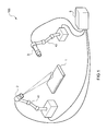
- an illumination/image-pickup system for surface inspection 100 includes a lighting device 2, an image-pickup device 3, robot arms 41 and 42 supporting the lighting device 2 and the image-pickup device 3 in a manner that the position and attitude thereof can be varied and an information processing device 5 so as to perform an image-pickup of an inspection object 1 while illuminating the inspection object 1 from a plurality of positions, so that a surface of a partial or entire portion of the inspection object 1 is inspected.
- a lighting device 2 an image-pickup device 3
- robot arms 41 and 42 supporting the lighting device 2 and the image-pickup device 3 in a manner that the position and attitude thereof can be varied
- an information processing device 5 so as to perform an image-pickup of an inspection object 1 while illuminating the inspection object 1 from a plurality of positions, so that a surface of a partial or entire portion of the inspection object 1 is inspected.
- the lighting device 2 uses, e.g., an LED, and although a spot-illuminating type one is used here, it is not limited to this, and ring type one or dome type one etc. may be used, and also a halogen light may be used as a light source.
- a spot-illuminating type one is used here, it is not limited to this, and ring type one or dome type one etc. may be used, and also a halogen light may be used as a light source.
- the image-pickup device 3 is adapted to a so-called FA (factory automation) use, utilizing a light receiving optical system such as camera lenses and a CCD or CMOS sensor for receiving and sensing the light passed through the light receiving optical system.
- a light receiving optical system such as camera lenses and a CCD or CMOS sensor for receiving and sensing the light passed through the light receiving optical system.
- the robot arms 41 and 42 support the lighting device 2 and the image-pickup device 3 and set the attitudes and positions thereof with, for example, three degrees of freedom, respectively (wherein the attitude and position are synonymous with "position" in the present invention).
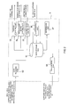
- the information processing device 5 is a so-called computer including a CPU, a memory and an I/O channel etc. and the CPU and peripheral equipment thereof are cooperated in accordance with a program stored in a memory thereof so as to perform functioning as a data storage part 51, a data receipt part 52, a position adjusting part 53, an image-pickup device control part 54, a lighting device control part 55, a compensation part 56, a determination part 57, a data sending part 58 and so forth as shown in Fig. 2 .
- the information processing device 5 as mentioned above may be independently installed or may be provided integrally with and annexed to the image-pickup device 3 or the lighting device 2 in terms of the physical viewpoint.
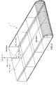
- the surface profile data includes a set of polygon data indicative of a polygon of such as a plane polygon (herein, e.g., quadrangle) which is a minimum unit, and coordinate data of each corner (herein, four points of the quadrangle) and vector data indicative of surface direction (normal direction to the surface) are given to each of the polygon data as shown in Fig. 3 .
- surface aspect data indicative of the surface aspects thereof may be coordinated with the respective polygon data.
- the surface aspect data means data indicative of surface roughness such as a mirror surface or a diffusing surface and a direction of a grain.
- an inspection object region which is a region to be desired to be subjected to surface inspection in the inspection object is first determined by operator's input operation and so forth.
- the inspection object region determined by the input operation etc. mentioned above is received by the data receipt part 52, and a set of polygon data existing in the inspection object region in the surface profile data is stored in the data storage part 51 as the inspection object region data.
- parameters adjustable in relation to the image-pickup device 3 i.e., a distance (also referred to as "work distance") between a prescribed point of the inspection object region and the image-pickup device 3, an image-pickup angle, an image-pickup scaling factor, an aperture etc. are determined by the above input operation and so forth.
- the parameters related to the image-pickup device determined by the input operation etc. are received by the data receipt part 52 and these parameters are stored in the data storage part 51.
- parameters adjustable in relation to the lighting device 2 i.e., a distance of the lighting device 2 to the inspection object region, an illuminating light angle, light quality (light emitting intensity and color of light) of the illuminating light etc. are determined by the above input operation and so forth.
- the parameters related to the lighting device determined by the input operation etc. are received by the data receipt part 52 and these parameters are stored in the data storage part 51.
- various information such as, e.g., camera lens parameters of the image-pickup device 3 and data according to depth of field etc. are previously stored in addition to the above parameters.
- the data storage part 51 stores: (1) the surface profile data indicative of the surface profile of the inspection object 1; (2) the inspection object region data indicative of the inspection object region; (3) the position related information data indicative of the position and attitude of the image-pickup device 3 with respect to the inspection object 1, i.e., data indicative of the work distance and the image-pickup angle specifying these position and attitude; (4) image-pickup condition data indicative of an image-pickup condition determined in the side of the image-pickup device 3, i.e., image-pickup scaling factor, aperture, camera lens parameter, depth of field, and solid angle of image-pickup visibility etc.; and (5) light illuminating aspect data indicative of the condition determining the light illuminating aspect to the inspection object 1 by the lighting device 2, i.e., the distance of the lighting device 2 to the inspection object region, the angle of illuminating light, the light quality of the illuminating light etc., and so forth.
- the position adjusting part 53 calculates the coordinate of the prescribed point (e.g., a center position) of the inspection object region referring to the surface profile data stored in the data storage part 51.
- the position adjusting part 53 outputs a control signal to be supplied to the robot arm 42 so as to set the relative position and the attitude with respect to the inspection object 1 of the image-pickup device 3 in a manner that, referring to the position related information data stored in the data storage part 51, an image-pickup axis is coincident with the prescribed point, the distance from the prescribed point to the image-pickup device 3 is coincident with the work distance indicative by the position related information data and that the angle defined between the normal direction at a prescribed point of the inspection object surface at the prescribed point (herein, the normal direction is specified by the polygon data including the prescribed point) and the image-pickup axis is coincident with the image-pickup angle indicative by the position related information data (herein the angle when the image-pickup axis is coincident with the normal direction, i.e., 0 degree).
- the position adjusting part 53 outputs a control signal to be supplied to the robot arm 41 so as to set the relative position and attitude with respect to the inspection object 1 of the lighting device 2 in a manner that, referring to the light illuminating aspect data stored in the data storage part 51, the distance between the prescribed point and the lighting device 2 becomes the distance indicated by the light illuminating aspect data and that the illumination light angle becomes the illumination angle indicated by the light illuminating aspect data.
- the lighting device control part 55 outputs a prescribed command signal to be supplied to the lighting device 2 so that the light emitted from the lighting device 2 is set to have a light quality and a light emitting intensity indicated by the light illuminating aspect data. Further, the image-pickup control part 54 outputs a prescribed command signal to be supplied to the image-pickup device 3 so that the image-pickup device is set to have an image-pickup scaling factor and an aperture indicated by the image-pickup condition data.
- the compensating part 56 calculates an image of the inspection object to be mapped in the captured image based on the position related information data, the image-pickup condition data and the surface profile data stored in the data storage part 51. Then, the compensating part 56 compares the calculated image and the actually picked up captured image and compensates the parameters that determines the calculated image so as to minimize a difference obtained by the comparison, i.e., compensates the position related information data, the image-pickup condition data and the surface profile data.
- the compensating part 56 compares the calculated image data and the actually captured image data referring to a singular point of the inspection object 1 such as an edge or a specified mark and so forth. And if there is a difference, a value of the position related information data or a value of a camera lens parameter indicative of such as, e.g., a lens distortion among the image-pickup condition data is compensated, and if there is an error in shape or size of the inspection object 1, the surface profile data of the inspection object region or a peripheral region thereof is compensated or the like so as to be consistent.
- the determining part 57 refers to the data stored in the data storage part 51 and specifies a valid image-pickup region which is valid for the inspection in the captured image using the surface profile of the inspection object 1, the work distance, the image-pickup angle, the image-pickup condition and the light illuminating aspect etc. indicated by the data as the determination parameters so as to be stored as the valid image-pickup region data in the data storage part.
- the following method can be exemplified. For example, a portion with a large distortion in the periphery of the captured image is specified using the camera lens parameter so as to exclude the peripheral region. Also, the peripheral portion outside the visibility is similarly removed by the solid angle of visibility. Also, for example, if it is determined based on the surface profile data that there is largely recessed into or protruded from the inspection object region from the depth of field so that the region departs from the depth of field, the region is excluded.
- the corresponding region is excluded.
- the region which is determined to be improper for the inspection as an image is masked and the determining part 57 specifies the remaining region excluding the masked region as the valid image-pickup region. Then, the valid image-pickup region data indicative of the valid image-pickup region is stored in the data storage part 51.
- the determining part 57 refers to the data stored in the data storage part 51 and specifies one or more image processing contents to be performed in the side of the image processing device based on the surface profile of the valid inspection region, work distance, image-pickup angle, image-pickup condition, light illuminating aspect and inspection contents according to scratch inspection or character identification etc. indicated by the data so as to be stored as the image processing specifying data in the data storage part 51.
- the image processing contents mean image processing kinds such as, e.g., binarization, brightness adjustment, extraction of color components, contrast adjustment, gamma correction, gray scaling, noise removal, blurring and so forth.
- adjustment parameters in each of the image processing may be added in addition to the image processing kinds.
- pixel value means a density or intensity of a pixel.
- the determining part 57 basically determines the image processing kinds referring to a corresponding table of inspection contents / image processing kinds previously stored in the memory and the like. For example, in the case where the inspection content is scratch inspection, the determining part 57 basically specifies the binarization as the image processing kind so as to determine the adjustment parameters such as a threshold value at this time based on the surface profile (including the surface aspect), image-pickup condition, light illuminating aspect and so forth. In addition to this, the brightness adjustment and contrast adjustment may be included in some cases. Moreover, in the case where the inspection content is character identification, the binarization or extraction of color components is selected as the image processing kind. It is noted that the image processing contents may be set by an operator's input operation.
- the information processing device 5 changes the positions and attitudes of the image-pickup device 3 and the lighting device 2 one or more times so as to be able to cover the inspection object region by the valid image-pickup region contained in the captured image data every time performing the image-pickup at each position.
- An overlap amount of each of the valid image-pickup regions may be determined in advance.
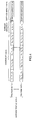
- Each captured image data thus subjected to the image-pickup is associated with the valid image-pickup region data and the image processing specifying data by the data sending part 58 so as to be transmitted to the image processing device.
- the remaining portion other than the valid image-pickup region in the received captured image data is masked and the image in the valid image-pickup region is subjected to image processing indicated by the image processing specifying data so as to output the image on a screen or performs determination in accordance with the inspection contents in some cases, i.e., the determination of a scratch being present or absent or character identification is automatically performed.
- the present embodiment configured as described above has a feature that a data structure of the captured image data associated with valid image-pickup region data and image processing specifying data is constructed in the side of the illumination/image-pickup system for surface inspection 100.
- the valid image-pickup region in the captured image and the image processing contents to be effected on the valid image-pickup region can be specified in addition to the captured image data so as to be transmitted to the image processing device. Therefore, the image processing can be performed in accordance with a common program in the side of the image processing device irrespective of the configuration of the illumination/image-pickup system for surface inspection 100. As a result, it becomes possible to promote generalization and standardization of the image processing device. It is noted that the present invention is not limited to the above embodiment.
- the lighting device and the image-pickup device are not necessarily movable relative to the inspection object, and so long as the environment in which the data structure of the present invention is usable is set, the present invention can be adapted to any inspection equipment so as to exert an equivalent effect.
- the present invention can be adapted to a simple plate etc. having a two dimensional shape as an inspection object.
- the present invention can be modified within a range unless deviated from the essence thereof.
- the valid image-pickup region in the captured image and the image processing contents to be effected on the valid image-pickup region can be specified in addition to the captured image data so as to be transmitted to the image processing device. Therefore, the image processing can be performed in accordance with a common program in the side of the image processing device irrespective of the configuration of the illumination/image-pickup system for surface inspection. As a result, it becomes possible to promote generalization and standardization of the image processing device.
Landscapes
- General Physics & Mathematics (AREA)
- Physics & Mathematics (AREA)
- Immunology (AREA)
- Pathology (AREA)
- Analytical Chemistry (AREA)
- Biochemistry (AREA)
- General Health & Medical Sciences (AREA)
- Life Sciences & Earth Sciences (AREA)
- Health & Medical Sciences (AREA)
- Chemical & Material Sciences (AREA)
- Engineering & Computer Science (AREA)
- Computer Vision & Pattern Recognition (AREA)
- Signal Processing (AREA)
- Investigating Materials By The Use Of Optical Means Adapted For Particular Applications (AREA)
- Length Measuring Devices By Optical Means (AREA)
- Image Analysis (AREA)
Applications Claiming Priority (2)
| Application Number | Priority Date | Filing Date | Title |
|---|---|---|---|
| JP2009203904 | 2009-09-03 | ||
| PCT/JP2010/065096 WO2011027848A1 (ja) | 2009-09-03 | 2010-09-03 | 表面検査用照明・撮像システム及びデータ構造 |
Publications (1)
| Publication Number | Publication Date |
|---|---|
| EP2474824A1 true EP2474824A1 (de) | 2012-07-11 |
Family
ID=43649383
Family Applications (1)
| Application Number | Title | Priority Date | Filing Date |
|---|---|---|---|
| EP10813795A Withdrawn EP2474824A1 (de) | 2009-09-03 | 2010-09-03 | Beleuchtungs-/bildaufnahmesystem für oberflächeninspektionen und datenstruktur dafür |
Country Status (7)
| Country | Link |
|---|---|
| US (1) | US20120162377A1 (de) |
| EP (1) | EP2474824A1 (de) |
| JP (1) | JP4675436B1 (de) |
| KR (1) | KR20120068014A (de) |
| CN (1) | CN102483380B (de) |
| SG (1) | SG178966A1 (de) |
| WO (1) | WO2011027848A1 (de) |
Cited By (1)
| Publication number | Priority date | Publication date | Assignee | Title |
|---|---|---|---|---|
| JP2025078741A (ja) * | 2020-02-16 | 2025-05-20 | オルボテック リミテッド | 電気回路の製造中にパターン付き物体の複数の特徴を検査するシステム及び方法 |
Families Citing this family (10)
| Publication number | Priority date | Publication date | Assignee | Title |
|---|---|---|---|---|
| WO2013038550A1 (ja) * | 2011-09-15 | 2013-03-21 | 日立Geニュークリア・エナジー株式会社 | 水中検査装置 |
| CN103543157B (zh) * | 2012-07-17 | 2015-12-02 | 宝山钢铁股份有限公司 | 离线带材表面图像模拟动态采集方法及装置 |
| JP2017086288A (ja) * | 2015-11-06 | 2017-05-25 | 大日本印刷株式会社 | コミュニケーションロボット及びプログラム |
| CN106091922B (zh) * | 2016-05-25 | 2019-05-14 | 广州市思林杰自动化科技有限公司 | 一种对工件进行检测的方法及装置 |
| WO2017210355A1 (en) * | 2016-05-31 | 2017-12-07 | Industrial Dynamics Company, Ltd. | Method and system for testing and inspecting containers using one or more light reflections and positional data |
| JP7383255B2 (ja) * | 2019-08-22 | 2023-11-20 | ナブテスコ株式会社 | 情報処理システム、情報処理方法、建設機械 |
| JP7531134B2 (ja) * | 2020-06-12 | 2024-08-09 | パナソニックIpマネジメント株式会社 | 検出方法および検出装置 |
| JP7695787B2 (ja) * | 2020-12-24 | 2025-06-19 | 株式会社前川製作所 | ロボットアーム用のツールチェック装置、ワーク加工システム、ツールチェックプログラム、及びツールチェック方法 |
| JP7775850B2 (ja) * | 2022-04-19 | 2025-11-26 | 株式会社村田製作所 | 外観検査装置 |
| WO2025253699A1 (ja) * | 2024-06-04 | 2025-12-11 | コニカミノルタ株式会社 | 検査領域設定装置、検査領域設定方法及び検査領域設定プログラム |
Family Cites Families (13)
| Publication number | Priority date | Publication date | Assignee | Title |
|---|---|---|---|---|
| JP3235387B2 (ja) * | 1991-07-12 | 2001-12-04 | オムロン株式会社 | 照明条件設定支援装置および方法 |
| WO1993001559A1 (en) * | 1991-07-12 | 1993-01-21 | Omron Corporation | Apparatus and method for determining or setting adequate illuminating and photographing condition, etc., in picture processing system; and apparatus and method for aiding the determination or setting |
| EP1857811A3 (de) * | 1999-03-18 | 2008-06-25 | JFE Steel Corporation | Verfahren und Vorrichtung zur Fehlermarkierung |
| US7105848B2 (en) * | 2002-04-15 | 2006-09-12 | Wintriss Engineering Corporation | Dual level out-of-focus light source for amplification of defects on a surface |
| JP2004226328A (ja) * | 2003-01-24 | 2004-08-12 | Hitachi Ltd | 外観検査システムおよびそれらを用いた品質評価システムおよび品質評価情報提供システム |
| US7084989B2 (en) * | 2004-04-19 | 2006-08-01 | Sick Ivp Aktiebolag | Measuring apparatus and method in a distribution system |
| JP2005345142A (ja) * | 2004-05-31 | 2005-12-15 | Tdk Corp | チップ部品の検査用装置及び検査方法 |
| KR100888235B1 (ko) * | 2004-07-09 | 2009-03-12 | 올림푸스 가부시키가이샤 | 화상 처리 장치 및 방법 |
| US20060012778A1 (en) * | 2004-07-12 | 2006-01-19 | August Technology Corp. | Illuminator for dark field inspection |
| US7397555B2 (en) * | 2004-12-17 | 2008-07-08 | Lam Research Corporation | System, method and apparatus for in-situ substrate inspection |
| JP4020144B2 (ja) * | 2006-03-10 | 2007-12-12 | オムロン株式会社 | 表面状態の検査方法 |
| CN101466999A (zh) * | 2006-06-12 | 2009-06-24 | 夏普株式会社 | 端部倾角测定方法、具有起伏的被检物的检测方法及检测装置、照明位置确定方法、不均匀缺陷检测装置和照明位置确定装置 |
| US7664608B2 (en) * | 2006-07-14 | 2010-02-16 | Hitachi High-Technologies Corporation | Defect inspection method and apparatus |
-
2010
- 2010-09-03 EP EP10813795A patent/EP2474824A1/de not_active Withdrawn
- 2010-09-03 CN CN201080039168.3A patent/CN102483380B/zh not_active Expired - Fee Related
- 2010-09-03 US US13/393,818 patent/US20120162377A1/en not_active Abandoned
- 2010-09-03 SG SG2012015061A patent/SG178966A1/en unknown
- 2010-09-03 JP JP2010541637A patent/JP4675436B1/ja not_active Expired - Fee Related
- 2010-09-03 KR KR1020127008359A patent/KR20120068014A/ko not_active Withdrawn
- 2010-09-03 WO PCT/JP2010/065096 patent/WO2011027848A1/ja not_active Ceased
Non-Patent Citations (1)
| Title |
|---|
| See references of WO2011027848A1 * |
Cited By (1)
| Publication number | Priority date | Publication date | Assignee | Title |
|---|---|---|---|---|
| JP2025078741A (ja) * | 2020-02-16 | 2025-05-20 | オルボテック リミテッド | 電気回路の製造中にパターン付き物体の複数の特徴を検査するシステム及び方法 |
Also Published As
| Publication number | Publication date |
|---|---|
| SG178966A1 (en) | 2012-04-27 |
| JPWO2011027848A1 (ja) | 2013-02-04 |
| CN102483380B (zh) | 2014-07-16 |
| KR20120068014A (ko) | 2012-06-26 |
| US20120162377A1 (en) | 2012-06-28 |
| WO2011027848A1 (ja) | 2011-03-10 |
| CN102483380A (zh) | 2012-05-30 |
| JP4675436B1 (ja) | 2011-04-20 |
Similar Documents
| Publication | Publication Date | Title |
|---|---|---|
| US20120162377A1 (en) | Illumination/image-pickup system for surface inspection and data structure | |
| US9533418B2 (en) | Methods and apparatus for practical 3D vision system | |
| CN110392252B (zh) | 用于生成相机的校正模型以校正像差的方法 | |
| CN106839986B (zh) | 一种基于机器视觉和机器学习的双工位载带检测系统 | |
| JP6608682B2 (ja) | 位置決め方法、外観検査装置、プログラム、コンピュータ可読記録媒体および外観検査方法 | |
| JP2021527220A (ja) | 空間内の複雑な表面上の点を特定するための方法および設備 | |
| CN110132166B (zh) | 一种可自动配光的产品图像检测方法及比对装置 | |
| CN120571781B (zh) | 基于视觉检测的包装缺陷剔除方法 | |
| CN110599450B (zh) | Led光源位置校正方法及系统 | |
| JP2015232487A (ja) | 画像検査装置、画像検査方法、画像検査プログラム及びコンピュータで読み取り可能な記録媒体並びに記録した機器 | |
| US10360684B2 (en) | Method and apparatus for edge determination of a measurement object in optical metrology | |
| CN107133983A (zh) | 成捆圆钢端面双目视觉系统与空间定位及计数方法 | |
| US10891750B2 (en) | Projection control device, marker detection method, and storage medium | |
| US20210025834A1 (en) | Image Capturing Devices and Associated Methods | |
| CN218788002U (zh) | 表面缺陷检测系统及表面检测产线 | |
| CN116137893A (zh) | 检查装置、检查方法以及活塞的制造方法 | |
| CN218629551U (zh) | 表面缺陷检测系统及表面检测产线 | |
| ES2949050T3 (es) | Procedimiento y dispositivo para la alineación precisa del ángulo de rotación de un neumático sobre una llanta | |
| TWI577979B (zh) | 光源通道校正方法及系統 | |
| EP4361880A1 (de) | Automatische beleuchtungsumschaltung für eine abtastvorrichtung mit reflexionen | |
| JPH01274954A (ja) | 自動化された追跡ならびに輪郭形状測定装置 | |
| KR20250034890A (ko) | 인공지능 기반 형상불량 검출 시스템 및 방법 | |
| CN104406986A (zh) | 一种药瓶机器视觉检测系统 | |
| CN111906043A (zh) | 位姿检测方法及系统 | |
| TWI804865B (zh) | 用於車輛牌照之光度測量的方法及裝置 |
Legal Events
| Date | Code | Title | Description |
|---|---|---|---|
| PUAI | Public reference made under article 153(3) epc to a published international application that has entered the european phase |
Free format text: ORIGINAL CODE: 0009012 |
|
| 17P | Request for examination filed |
Effective date: 20120314 |
|
| AK | Designated contracting states |
Kind code of ref document: A1 Designated state(s): AL AT BE BG CH CY CZ DE DK EE ES FI FR GB GR HR HU IE IS IT LI LT LU LV MC MK MT NL NO PL PT RO SE SI SK SM TR |
|
| DAX | Request for extension of the european patent (deleted) | ||
| STAA | Information on the status of an ep patent application or granted ep patent |
Free format text: STATUS: THE APPLICATION HAS BEEN WITHDRAWN |
|
| 18W | Application withdrawn |
Effective date: 20140811 |