EP2474866A1 - Bilderzeugungsvorrichtung - Google Patents
Bilderzeugungsvorrichtung Download PDFInfo
- Publication number
- EP2474866A1 EP2474866A1 EP11195224A EP11195224A EP2474866A1 EP 2474866 A1 EP2474866 A1 EP 2474866A1 EP 11195224 A EP11195224 A EP 11195224A EP 11195224 A EP11195224 A EP 11195224A EP 2474866 A1 EP2474866 A1 EP 2474866A1
- Authority
- EP
- European Patent Office
- Prior art keywords
- guide
- conveyance
- roller
- unit
- transfer roller
- Prior art date
- Legal status (The legal status is an assumption and is not a legal conclusion. Google has not performed a legal analysis and makes no representation as to the accuracy of the status listed.)
- Granted
Links
Images





Classifications
-
- G—PHYSICS
- G03—PHOTOGRAPHY; CINEMATOGRAPHY; ANALOGOUS TECHNIQUES USING WAVES OTHER THAN OPTICAL WAVES; ELECTROGRAPHY; HOLOGRAPHY
- G03G—ELECTROGRAPHY; ELECTROPHOTOGRAPHY; MAGNETOGRAPHY
- G03G15/00—Apparatus for electrographic processes using a charge pattern
- G03G15/14—Apparatus for electrographic processes using a charge pattern for transferring a pattern to a second base
-
- G—PHYSICS
- G03—PHOTOGRAPHY; CINEMATOGRAPHY; ANALOGOUS TECHNIQUES USING WAVES OTHER THAN OPTICAL WAVES; ELECTROGRAPHY; HOLOGRAPHY
- G03G—ELECTROGRAPHY; ELECTROPHOTOGRAPHY; MAGNETOGRAPHY
- G03G21/00—Arrangements not provided for by groups G03G13/00 - G03G19/00, e.g. cleaning, elimination of residual charge
- G03G21/16—Mechanical means for facilitating the maintenance of the apparatus, e.g. modular arrangements
- G03G21/1661—Mechanical means for facilitating the maintenance of the apparatus, e.g. modular arrangements means for handling parts of the apparatus in the apparatus
-
- G—PHYSICS
- G03—PHOTOGRAPHY; CINEMATOGRAPHY; ANALOGOUS TECHNIQUES USING WAVES OTHER THAN OPTICAL WAVES; ELECTROGRAPHY; HOLOGRAPHY
- G03G—ELECTROGRAPHY; ELECTROPHOTOGRAPHY; MAGNETOGRAPHY
- G03G21/00—Arrangements not provided for by groups G03G13/00 - G03G19/00, e.g. cleaning, elimination of residual charge
- G03G21/16—Mechanical means for facilitating the maintenance of the apparatus, e.g. modular arrangements
- G03G21/1661—Mechanical means for facilitating the maintenance of the apparatus, e.g. modular arrangements means for handling parts of the apparatus in the apparatus
- G03G21/168—Mechanical means for facilitating the maintenance of the apparatus, e.g. modular arrangements means for handling parts of the apparatus in the apparatus for the transfer unit
-
- G—PHYSICS
- G03—PHOTOGRAPHY; CINEMATOGRAPHY; ANALOGOUS TECHNIQUES USING WAVES OTHER THAN OPTICAL WAVES; ELECTROGRAPHY; HOLOGRAPHY
- G03G—ELECTROGRAPHY; ELECTROPHOTOGRAPHY; MAGNETOGRAPHY
- G03G21/00—Arrangements not provided for by groups G03G13/00 - G03G19/00, e.g. cleaning, elimination of residual charge
- G03G21/16—Mechanical means for facilitating the maintenance of the apparatus, e.g. modular arrangements
- G03G21/1604—Arrangement or disposition of the entire apparatus
- G03G21/1623—Means to access the interior of the apparatus
- G03G21/1633—Means to access the interior of the apparatus using doors or covers
-
- G—PHYSICS
- G03—PHOTOGRAPHY; CINEMATOGRAPHY; ANALOGOUS TECHNIQUES USING WAVES OTHER THAN OPTICAL WAVES; ELECTROGRAPHY; HOLOGRAPHY
- G03G—ELECTROGRAPHY; ELECTROPHOTOGRAPHY; MAGNETOGRAPHY
- G03G21/00—Arrangements not provided for by groups G03G13/00 - G03G19/00, e.g. cleaning, elimination of residual charge
- G03G21/16—Mechanical means for facilitating the maintenance of the apparatus, e.g. modular arrangements
- G03G21/1642—Mechanical means for facilitating the maintenance of the apparatus, e.g. modular arrangements for connecting the different parts of the apparatus
- G03G21/1647—Mechanical connection means
-
- G—PHYSICS
- G03—PHOTOGRAPHY; CINEMATOGRAPHY; ANALOGOUS TECHNIQUES USING WAVES OTHER THAN OPTICAL WAVES; ELECTROGRAPHY; HOLOGRAPHY
- G03G—ELECTROGRAPHY; ELECTROPHOTOGRAPHY; MAGNETOGRAPHY
- G03G21/00—Arrangements not provided for by groups G03G13/00 - G03G19/00, e.g. cleaning, elimination of residual charge
- G03G21/16—Mechanical means for facilitating the maintenance of the apparatus, e.g. modular arrangements
- G03G21/1661—Mechanical means for facilitating the maintenance of the apparatus, e.g. modular arrangements means for handling parts of the apparatus in the apparatus
- G03G21/1695—Mechanical means for facilitating the maintenance of the apparatus, e.g. modular arrangements means for handling parts of the apparatus in the apparatus for paper transport
-
- G—PHYSICS
- G03—PHOTOGRAPHY; CINEMATOGRAPHY; ANALOGOUS TECHNIQUES USING WAVES OTHER THAN OPTICAL WAVES; ELECTROGRAPHY; HOLOGRAPHY
- G03G—ELECTROGRAPHY; ELECTROPHOTOGRAPHY; MAGNETOGRAPHY
- G03G2215/00—Apparatus for electrophotographic processes
- G03G2215/16—Transferring device, details
- G03G2215/1604—Main transfer electrode
- G03G2215/1623—Transfer belt
-
- G—PHYSICS
- G03—PHOTOGRAPHY; CINEMATOGRAPHY; ANALOGOUS TECHNIQUES USING WAVES OTHER THAN OPTICAL WAVES; ELECTROGRAPHY; HOLOGRAPHY
- G03G—ELECTROGRAPHY; ELECTROPHOTOGRAPHY; MAGNETOGRAPHY
- G03G2221/00—Processes not provided for by group G03G2215/00, e.g. cleaning or residual charge elimination
- G03G2221/16—Mechanical means for facilitating the maintenance of the apparatus, e.g. modular arrangements and complete machine concepts
- G03G2221/1642—Mechanical means for facilitating the maintenance of the apparatus, e.g. modular arrangements and complete machine concepts for the transfer unit
-
- G—PHYSICS
- G03—PHOTOGRAPHY; CINEMATOGRAPHY; ANALOGOUS TECHNIQUES USING WAVES OTHER THAN OPTICAL WAVES; ELECTROGRAPHY; HOLOGRAPHY
- G03G—ELECTROGRAPHY; ELECTROPHOTOGRAPHY; MAGNETOGRAPHY
- G03G2221/00—Processes not provided for by group G03G2215/00, e.g. cleaning or residual charge elimination
- G03G2221/16—Mechanical means for facilitating the maintenance of the apparatus, e.g. modular arrangements and complete machine concepts
- G03G2221/1678—Frame structures
- G03G2221/169—Structural door designs
Definitions
- the present disclosure relates to an image forming apparatus.
- a so-called electrographic type of image forming apparatus includes a type in which a conveyance unit provided with a transfer roller is mounted in an opening and closing configuration on a main body provided with an image carrier that forms a toner image on a surface thereof.
- This type of image forming apparatus is configured to bring the transfer roller into abutment with the image carrier by placing the conveyance unit in a closed state, and to thereby form a transfer nip portion for transfer of the resulting toner image onto a sheet of paper.
- an image forming apparatus with the above configuration has a transfer roller forward conveyance guide for guiding the paper sheet to the transfer nip portion.
- a transfer roller forward conveyance guide for guiding the paper sheet to the transfer nip portion.
- a configuration is known in which the conveyance guide is fixed to the conveyance unit, and when the conveyance unit is in a closed state, the conveyance guide fixed to the conveyance unit is displaced towards the main body, abuts with a position locating portion of the main body and thereby locates the position of the conveyance guide on the main body.
- a configuration in a related technique is known in which a locating projection provided in proximity to the conveyance guide is inserted into a locating hole provided on the main body in response to the closing operation of the conveyance unit to thereby position the conveyance guide on the main body.
- the present disclosure has the object of providing an image forming apparatus enabling stable abutment of the conveyance guide with a guide locating portion provided on the main body.
- This disclosure relates to an image forming apparatus comprising a main body and a conveyance unit.
- the main body includes an image carrier, a roller locating portion, and a guide locating portion.
- the image carrier has one or a plurality of mutually parallel shafts and forming a toner image on a surface.
- the roller locating portion is formed on both axial ends of the image carrier.
- the guide locating portion is formed in proximity to the roller locating portion.
- the conveyance unit is mounted to open and close on the main body, and includes a transfer roller unit, a conveyance guide, and a biasing member.
- the transfer roller unit has a transfer roller abutting with image carrier and forming a transfer nip portion with the image carrier, and a separation lever configured to provide pivotal support for the transfer roller and being disposed to rotate.
- the conveyance guide is configured to guide a sheet of paper to the transfer nip portion, includes a regulating portion and is disposed to rotate.
- the biasing member is configured to bias the conveyance guide toward the guide locating portion.
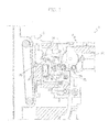
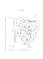
- a color printer 1 will be described below as an image forming apparatus according to a first embodiment of the present disclosure making reference to FIG. 1 to FIG. 14 .
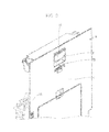
- the front face illustrated in FIG. 1 and FIG. 2 will be described below as the front surface of the color printer 1.
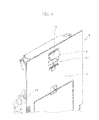
- the right/left positional relationship of each member in FIG. 3 , FIG. 4 , FIG. 7 and FIG. 8 is inverted with respect to that illustrated in FIG. 1 and FIG. 2 .
- the color printer 1 includes a main body 2 in which an outer periphery is covered by an external cover (not shown) and a conveyance unit 3 mounted to open and close on a left surface of the main body 2.
- an intermediate transfer belt 4 that configures an image carrier is supported horizontally from the left portion to the right portion in an inner portion of the main body 2.
- the intermediate transfer belt 4 includes a plurality of shafts that extend in a vertical direction with respect to the sheet of paper of FIG. 1 .
- the plurality of shafts is disposed in a mutually parallel configuration. More precisely, the intermediate transfer belt 4 is formed in a circular configuration.
- the intermediate transfer belt 4 is suspended on a plurality of rotating rollers disposed on an inner surface in a circular configuration.
- the intermediate transfer belt 4 is rotated in a circular direction by the plurality of rotating rollers rotating about a shaft (axis).
- the intermediate transfer belt 4 may be described as rotating about an axis in a region abutting with the rotating roller.
- the transfer roller may be used as the image carrier.
- the transfer roller has a single shaft and rotates about that shaft (axis). In each figure, only the left end of the intermediate transfer belt 4 is displayed by a dotted line.
- An roller locating portion 5 which is indented portion is formed in the main body 2 on both ends with respect to an axial direction of the intermediate transfer belt 4 (a longitudinal direction in the present embodiment) (refer to FIG.1 ).
- the roller locating portion 5 is formed in a semi-arc shape opening towards the lower left when viewed in section.
- the guide locating portion 6 which is flat face is disposed to extend in a substantially perpendicular direction in proximity to the roller locating portion 5 on the main body 2 (more on an inner axial direction than the roller locating portion 5) (refer to FIG. 2 ).
- an image forming unit is provided for respective colors on the main body 2.
- the image forming unit includes a photosensitive drum that abut with the intermediate transfer belt 4 and form a primary transfer nip portion, a charging device that applies a charge to a predetermined voltage to the surface of each photosensitive drum, an exposure device that exposes light onto the surface of each photosensitive drum that has been charged by the charging device to thereby form an electrostatic latent image, a development device that uses toner to develop the electrostatic latent image formed by the exposure device into a toner image, and a primary transfer roller that operates cooperatively with the photosensitive drum to execute primary transfer of the toner image onto the surface of the intermediate transfer belt 4.
- the conveyance unit 3 is configured to open and close with respect to the main body 2 by revolving (rotating) about a support point (not shown) provided on a lower end portion.
- the conveyance unit 3 is configured to be displaceable between a closed state and an open state.
- the conveyance unit 3 includes a left cover 7 that covers the left surface of the main body 2, an opening and closing lever 8 that is mounted on an upper portion of the left cover 7, a transfer roller unit 11 connected with the opening and closing lever 8 though a link mechanism 10, and a conveyance guide 12 provided below the transfer roller unit 11.
- the opening and closing lever 8 is configured to be in the shape of a letter "L" when viewed in cross section.
- the opening and closing lever 8 includes a handle 14 disposed in an indented portion 13 (refer to FIG. 3 and FIG. 4 ) formed on an upper portion of the outer surface (left surface) of the left cover 7, a pressing portion 15 curving to the right from an upper end of the handle 14, and a support portion 16 mounted in proximity to a connecting portion with the handle 14 and the pressing portion 15.
- the opening and closing lever 8 is supported on the conveyance unit 3 to rotate about the support portion 16.
- the opening and closing lever 8 is operably connected with a hook (not illustrated) that engages with an engaging portion (not illustrated) formed on the main body 2 to thereby maintain the conveyance unit 3 in a closed state.
- the link mechanism 10 includes a link member 17 provided below the opening and closing lever 8 and a lock lever 18 provided from below the link member 17 to the lower right.
- the link member 17 is provided along the inner surface (right surface) of the left cover 7.
- the link member 17 is supported to shift vertically on the conveyance unit 3.
- An upper end projection 20 is provided towards the right on an upper end of the link member 17.
- the upper surface of the upper end projection 20 abuts with the lower surface of the pressing portion 15 of the opening and closing lever 8.
- a lower end projection 21 is provided towards the right on a lower end of the link member 17.
- a pressing projection 19 is provided in a downward configuration on a right end of the lower end projection 21.
- the lock lever 18 is supported to revolve (rotate) on the conveyance unit 3.
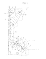
- a torsion spring (not illustrated) is housed in the lock lever 18 and a spring pressure is applied by the torsion spring to place the lock lever 18 in a horizontal state (refer to FIG. 5 ).
- An inclined surface 43 is provided at a position on the upper left portion of the lock lever 18 corresponding to the pressing projection 19 of the link member 17.
- a projecting engagement portion 44 is provided to the left of the inclined surface 43.
- a raising projection 23 is provided towards the lower right on the right end portion of the lock lever 18.
- the transfer roller unit 11 includes a secondary transfer roller 2 5 provided to abut with the intermediate transfer belt 4, and a separation lever 26 provided on both ends in an axial direction of the secondary transfer roller 2 5 (in the longitudinal direction in the present embodiment).
- the secondary transfer roller 25 forms a secondary transfer nip portion 24 with the intermediate transfer belt 4.
- a toner image that is subjected to primary transfer onto the surface of the intermediate transfer belt 4 by the primary transfer roller (not illustrated) can be secondarily transferred to a sheet of paper by the secondary transfer nip portion 24.
- a pivotal supporting portion 27 which is circular shape is provided on a right end of the separation lever 26.
- the secondary transfer roller 25 is pivotally supported on the separation lever 26 by insertion of both longitudinal ends of the rotation shaft 28 of the secondary transfer roller 25 into the pivotal support portion 2 7.
- An elongated hole 29 is provided in a central portion in the transverse direction of the separation lever 26.
- the separation lever 26 is retained to revolve (rotate) about a projection 30 by engagement of the boss-shaped projection 30 provided on both longitudinal ends of the conveyance unit 3 in the elongated hole 29.
- An engaging portion 31 is provided on the left end portion of the separation lever 26 at a position corresponding to the raising projection 23 of the lock lever 18.
- the conveyance guide 12 is biased towards the guide locating portion 6 (refer to the arrow in FIG. 2 ) by the torsion spring (not illustrated) that acts as a biasing member provided on the conveyance unit 3.
- the conveyance guide 12 includes a guide plate 32 elongated in a longitudinal direction, an upper end curved plate 33 provided from the upper end of the guide plate 32 towards an upper left direction, and both end curved plates 34, 35 that are orientated towards the left respectively on both ends in a longitudinal direction of the guide plate 32.
- the guide plate 32 is disposed in a substantially perpendicular orientation (a configuration in which the planar direction is parallel to the vertical direction) (refer to FIG. 8 ).
- the guide plate 32 is configured so that a sheet of paper that is conveyed from below the conveyance guide 12 rises along the right surface of the guide plate 32 and is guided to the secondary transfer nip portion 24.
- a notched portion 36 is provided on both ends in a longitudinal direction of the upper end curved plate 33 and the guide plate 32 from the upper portion of the guide plate 32 towards the upper end curved plate 33.
- An engaging hole 37 is provided in a horizontal configuration on a lower portion each of the both end curved plates 34, 35.
- the conveyance guide 12 is supported to revolve (rotate) on a conveyance unit 3 by engagement of the boss 38 (refer to FIG. 2 ) provided on both longitudinal ends of the conveyance unit 3 with the engaging hole 3 7.
- the engaging hole 3 7 of the forward end curved plate 34 is formed as an elongated hole (refer to FIG. 2 ), and the engaging hole 37 of the rear end curved plate 35 is formed as a precise circle, and includes an open portion that has a smaller width than the diameter (refer to FIG. 7 ).
- the forward-end boss 38 is cylindrical, and a portion of the peripheral surface of the cylinder of the rear-end boss 38 is cut to form a width that enables passage of the open portion of the rear end curved plate 35.
- the boss 38 is inserted into the engaging hole 37 of the forward-end curved plate 34, the rear end boss 38 is aligned and inserted into the open portion of the engaging hole 37 of the rear end curved plate 35, and thereby enables simple mounting of the conveyance guide 12 on the conveyance unit 3.
- one longitudinal end of the conveyance guide 12 is rotatably supported on the conveyance unit 3, and the other end is supported to rotate on the conveyance unit 3 and shifts in a predetermined direction.
- An abutment piece 39 is oriented toward the right on an upper end of the right edge each of the both end curved plates 34, 35.
- a curved piece 40 is oriented toward the notched portion 36 on a right end of the upper edge portion each of the both end curved plates 34, 35.
- One end of the torsion spring is engaged with the curved piece 40 and biases the conveyance guide 12 towards the guide locating portion 6.
- a regulating portion 41 is oriented towards the upper left on the left end each of the both end curved plates 34, 35.
- the regulating portion 41 of the forward end curved plate 34 is provided in a flat plate shape, and the regulating portion 41 of the rear end curved plate 35 curves in the shape of a letter L (refer to FIG. 7 ).
- the pivotal supporting portion 27 is disposed at a position engaging with the roller locating portion 5 to thereby position the secondary transfer roller 25.
- the secondary transfer nip portion 24 is formed by abutment with a predetermined pressure of the secondary transfer roller 25 with the intermediate transfer belt 4.
- the conveyance guide 12 is pressed by the torsion spring (not illustrated) towards the guide locating portion 6 of the main body 2, and the conveyance guide 12 is located by abutment of the abutment piece 39 of the conveyance guide 12 at a predetermined pressure with the guide 10-cating portion 6.
- the pivotal supporting portion 2 7 of the separation lever 26 separates from the regulating portion 41 of the conveyance guide 12.
- the opening and closing lever 8 revolves (rotates) about the support portion 16 as illustrated in FIG. 6 , and the pressing portion 15 of the opening and closing lever 8 depresses the upper end projection 20 of the link member 17 downwardly.
- the link member 17 is lowered, the pressing projection 19 of the link member 17 presses the inclined surface 43 of the lock lever 18 downwardly.
- the lock lever 18 revolves (rotates). The revolving (rotation) of the lock lever 18 raises the raising projection 23 of the lock lever 18 and the engaging portion 31 of the separation lever 26 is pressed upwardly.
- the separation lever 26 revolves (rotates) about the projection 30 and is pressed upwardly. As illustrated in FIG. 9 , in this manner, the pivotal supporting portion 27 of the separation lever 26 displaces by revolving (rotating) from the engaging position with the transfer roller locating portion 5 to the separation position. As illustrated in FIG. 10 , the pivotal supporting portion 27 of the separation lever 26 abuts with the regulating portion 41 of the conveyance guide 12.
- the pivotal supporting portion 27 of the separation lever 26 becomes completely separated from the roller locating portion 5.
- the conveyance guide 12 is further separated from the guide locating portion 6.
- the separation operation from the roller locating portion 5 of the secondary transfer roller 25 is operably connected to the separation from the guide locating portion 6 on the conveyance guide 12. Therefore, resistance during opening of the conveyance unit 3 is reduced, and contact between the transfer surface of the transfer roller 25 and the conveyance guide 12 can be prevented.
- the pivotal supporting portion 27 of the separation lever 26 engages with the roller locating portion 5.
- the pivotal supporting portion 27 of the separation lever 26 displaces by revolving (rotating) from a separation position with the roller locating portion 5 to an engagement position. In this manner, the secondary transfer roller 25 is positioned.
- the pivotal supporting portion 27 separates from the regulating portion 41 as a result of the displacement by revolving (rotating) of the pivotal supporting portion 27, and the conveyance guide 12 abuts with the guide locating portion 6 as a result of the biasing force of the torsion spring.
- the conveyance guide 12 is maintained in a state of abutment with the guide locating portion 6. In this manner, the rear end side of the conveyance guide 12 is located by the guide locating portion 6 and the rear end boss 38 and the conveyance unit 3. The front end of the conveyance unit 12 is located vertically and transversely in the same orientation as the rear end by the guide locating portion 6 and the front end boss 38 and the conveyance unit 3.
- the secondary transfer nip portion 24 is formed by abutment of the secondary transfer roller 25 at a predetermined pressure with the intermediate transfer belt 4.
- the color printer 1 (image forming apparatus) according to the present embodiment is configured to enable accurate and stable abutment of the conveyance guide 12 with the guide locating portion 6 of the main body 2, and thereby prevent unsatisfactory image quality, paper jams, and malfunction in relation to opening and closing operations.
- the color printer 1 (image forming apparatus) is configured to operably connect the locating operation in relation to the secondary transfer roller 25 and the conveyance guide 12, locating of both members can be more accurately executed.
- the image forming apparatus may be a monochrome printer, a monochrome or color copying machine, a facsimile, or a multifunction peripheral combining such devices.
- the image forming apparatus may be a so-called electrographic type of image forming apparatus.
Landscapes
- Physics & Mathematics (AREA)
- General Physics & Mathematics (AREA)
- Electrostatic Charge, Transfer And Separation In Electrography (AREA)
- Electrophotography Configuration And Component (AREA)
- Delivering By Means Of Belts And Rollers (AREA)
Applications Claiming Priority (1)
| Application Number | Priority Date | Filing Date | Title |
|---|---|---|---|
| JP2010289143A JP5346914B2 (ja) | 2010-12-27 | 2010-12-27 | 画像形成装置 |
Publications (2)
| Publication Number | Publication Date |
|---|---|
| EP2474866A1 true EP2474866A1 (de) | 2012-07-11 |
| EP2474866B1 EP2474866B1 (de) | 2019-11-06 |
Family
ID=45507356
Family Applications (1)
| Application Number | Title | Priority Date | Filing Date |
|---|---|---|---|
| EP11195224.8A Active EP2474866B1 (de) | 2010-12-27 | 2011-12-22 | Bilderzeugungsvorrichtung |
Country Status (5)
| Country | Link |
|---|---|
| US (1) | US8682217B2 (de) |
| EP (1) | EP2474866B1 (de) |
| JP (1) | JP5346914B2 (de) |
| KR (1) | KR101292953B1 (de) |
| CN (1) | CN102566373B (de) |
Cited By (1)
| Publication number | Priority date | Publication date | Assignee | Title |
|---|---|---|---|---|
| EP3220204A4 (de) * | 2015-04-06 | 2018-07-18 | Kyocera Document Solutions Inc. | Bilderzeugungsvorrichtung |
Families Citing this family (15)
| Publication number | Priority date | Publication date | Assignee | Title |
|---|---|---|---|---|
| JP5919935B2 (ja) * | 2012-03-23 | 2016-05-18 | 富士ゼロックス株式会社 | 画像形成装置 |
| US9031461B2 (en) * | 2013-03-15 | 2015-05-12 | Lexmark International, Inc. | Transfer roll assembly for an electrophotographic image forming device |
| JP6508143B2 (ja) * | 2016-08-08 | 2019-05-08 | 京セラドキュメントソリューションズ株式会社 | 転写ユニット及び画像形成装置 |
| US11551028B2 (en) | 2017-04-04 | 2023-01-10 | Hailo Technologies Ltd. | Structured weight based sparsity in an artificial neural network |
| US11238334B2 (en) | 2017-04-04 | 2022-02-01 | Hailo Technologies Ltd. | System and method of input alignment for efficient vector operations in an artificial neural network |
| US11615297B2 (en) | 2017-04-04 | 2023-03-28 | Hailo Technologies Ltd. | Structured weight based sparsity in an artificial neural network compiler |
| US11544545B2 (en) | 2017-04-04 | 2023-01-03 | Hailo Technologies Ltd. | Structured activation based sparsity in an artificial neural network |
| US10387298B2 (en) | 2017-04-04 | 2019-08-20 | Hailo Technologies Ltd | Artificial neural network incorporating emphasis and focus techniques |
| US12430543B2 (en) | 2017-04-04 | 2025-09-30 | Hailo Technologies Ltd. | Structured sparsity guided training in an artificial neural network |
| KR102931058B1 (ko) | 2017-12-05 | 2026-02-24 | 삼성전자주식회사 | 뉴럴 네트워크에서 컨볼루션 연산을 처리하는 방법 및 장치 |
| US11237894B1 (en) | 2020-09-29 | 2022-02-01 | Hailo Technologies Ltd. | Layer control unit instruction addressing safety mechanism in an artificial neural network processor |
| US11263077B1 (en) | 2020-09-29 | 2022-03-01 | Hailo Technologies Ltd. | Neural network intermediate results safety mechanism in an artificial neural network processor |
| US11811421B2 (en) | 2020-09-29 | 2023-11-07 | Hailo Technologies Ltd. | Weights safety mechanism in an artificial neural network processor |
| US12248367B2 (en) | 2020-09-29 | 2025-03-11 | Hailo Technologies Ltd. | Software defined redundant allocation safety mechanism in an artificial neural network processor |
| US11221929B1 (en) | 2020-09-29 | 2022-01-11 | Hailo Technologies Ltd. | Data stream fault detection mechanism in an artificial neural network processor |
Citations (3)
| Publication number | Priority date | Publication date | Assignee | Title |
|---|---|---|---|---|
| US20040013452A1 (en) * | 2002-07-22 | 2004-01-22 | Samsung Electronics Co., Ltd | Transferring apparatus of color laser printer |
| US20070080493A1 (en) * | 2005-10-07 | 2007-04-12 | Samsung Electronics Co., Ltd. | Printing medium feeding apparatus and image forming apparatus using the same |
| US20070127947A1 (en) * | 2005-12-07 | 2007-06-07 | Kazuosa Kuma | Image forming apparatus capable of effectively performing a maintenance operation |
Family Cites Families (20)
| Publication number | Priority date | Publication date | Assignee | Title |
|---|---|---|---|---|
| JP3054892B2 (ja) * | 1992-02-27 | 2000-06-19 | 富士通株式会社 | 電子写真装置の光学式ヘッド取付構造 |
| EP0549812B1 (de) | 1991-07-16 | 1997-09-24 | Fujitsu Limited | Montagestruktur für eine anordnung von lichtemittierenden elementen in einem elektrophotographischen gerät |
| JPH0830054A (ja) * | 1994-07-11 | 1996-02-02 | Canon Inc | 画像形成装置 |
| JPH1130896A (ja) * | 1997-07-10 | 1999-02-02 | Canon Inc | 画像形成装置 |
| JP3342426B2 (ja) | 1998-11-30 | 2002-11-11 | キヤノン株式会社 | 画像形成装置 |
| JP3735045B2 (ja) * | 2001-03-21 | 2006-01-11 | シャープ株式会社 | 画像形成装置 |
| JP3748784B2 (ja) * | 2001-03-21 | 2006-02-22 | シャープ株式会社 | 画像形成装置 |
| US6795669B2 (en) | 2001-02-02 | 2004-09-21 | Sharp Kabushiki Kaisha | Image device with control members for rollers |
| JP2004240329A (ja) * | 2003-02-07 | 2004-08-26 | Kyocera Mita Corp | 画像形成装置 |
| JP4534472B2 (ja) * | 2003-12-05 | 2010-09-01 | 富士ゼロックス株式会社 | 画像形成装置 |
| JP4528556B2 (ja) * | 2004-05-18 | 2010-08-18 | 京セラミタ株式会社 | 画像形成装置の転写材搬送ガイド機構 |
| JP4613538B2 (ja) * | 2004-07-16 | 2011-01-19 | 村田機械株式会社 | 画像形成装置 |
| JP4254689B2 (ja) * | 2004-11-01 | 2009-04-15 | 船井電機株式会社 | レーザビームプリンタ |
| US7460814B2 (en) * | 2005-10-26 | 2008-12-02 | Kyocera Mita Corporation | Image device having an opening/closing cover |
| JP2007240834A (ja) * | 2006-03-08 | 2007-09-20 | Kyocera Mita Corp | 画像形成装置 |
| JP4974290B2 (ja) * | 2007-07-17 | 2012-07-11 | 株式会社リコー | 画像形成装置 |
| US8116663B2 (en) * | 2007-11-16 | 2012-02-14 | Kabushiki Kaisha Toshiba | Image forming apparatus with a secondary-transfer-roller releasing mechanism |
| JP2010230775A (ja) * | 2009-03-26 | 2010-10-14 | Brother Ind Ltd | 画像形成装置 |
| JP5071433B2 (ja) * | 2009-05-01 | 2012-11-14 | 富士ゼロックス株式会社 | 画像形成装置 |
| JP5344599B2 (ja) * | 2009-06-11 | 2013-11-20 | キヤノン株式会社 | 画像形成装置 |
-
2010
- 2010-12-27 JP JP2010289143A patent/JP5346914B2/ja active Active
-
2011
- 2011-12-12 CN CN201110411249.8A patent/CN102566373B/zh active Active
- 2011-12-20 KR KR1020110138250A patent/KR101292953B1/ko active Active
- 2011-12-22 EP EP11195224.8A patent/EP2474866B1/de active Active
- 2011-12-22 US US13/334,660 patent/US8682217B2/en active Active
Patent Citations (3)
| Publication number | Priority date | Publication date | Assignee | Title |
|---|---|---|---|---|
| US20040013452A1 (en) * | 2002-07-22 | 2004-01-22 | Samsung Electronics Co., Ltd | Transferring apparatus of color laser printer |
| US20070080493A1 (en) * | 2005-10-07 | 2007-04-12 | Samsung Electronics Co., Ltd. | Printing medium feeding apparatus and image forming apparatus using the same |
| US20070127947A1 (en) * | 2005-12-07 | 2007-06-07 | Kazuosa Kuma | Image forming apparatus capable of effectively performing a maintenance operation |
Cited By (1)
| Publication number | Priority date | Publication date | Assignee | Title |
|---|---|---|---|---|
| EP3220204A4 (de) * | 2015-04-06 | 2018-07-18 | Kyocera Document Solutions Inc. | Bilderzeugungsvorrichtung |
Also Published As
| Publication number | Publication date |
|---|---|
| US8682217B2 (en) | 2014-03-25 |
| JP2012137576A (ja) | 2012-07-19 |
| US20120163863A1 (en) | 2012-06-28 |
| JP5346914B2 (ja) | 2013-11-20 |
| CN102566373A (zh) | 2012-07-11 |
| KR101292953B1 (ko) | 2013-08-02 |
| EP2474866B1 (de) | 2019-11-06 |
| CN102566373B (zh) | 2015-02-04 |
| KR20120074216A (ko) | 2012-07-05 |
Similar Documents
| Publication | Publication Date | Title |
|---|---|---|
| US8682217B2 (en) | Image forming apparatus | |
| US8401426B2 (en) | Opening/closing mechanism and image forming apparatus | |
| US8292290B2 (en) | Feeding device and image forming apparatus | |
| CN209356850U (zh) | 手动送纸托盘装置以及图像形成装置 | |
| JP4873487B2 (ja) | 画像形成装置 | |
| JP7375434B2 (ja) | シート給送装置及び画像形成装置 | |
| JP2007137559A (ja) | 給紙装置 | |
| JP2018138487A (ja) | シート積載装置、給送装置及び画像形成装置 | |
| JP4989311B2 (ja) | 画像形成装置 | |
| US10259674B2 (en) | Sheet discharging device and image forming apparatus therewith | |
| JP6922504B2 (ja) | 給送装置、及び、画像形成装置 | |
| US10338519B2 (en) | Image forming apparatus | |
| US9285708B2 (en) | Image forming apparatus | |
| JP2016005983A (ja) | 用紙排出装置及び画像形成装置 | |
| US9187275B2 (en) | Image forming apparatus | |
| JP7379047B2 (ja) | シート給送装置、及び画像形成装置 | |
| US11827476B2 (en) | Sheet feeding device and image forming apparatus | |
| JP3535671B2 (ja) | 画像形成装置 | |
| JP7636308B2 (ja) | シート供給装置及びこれを備えた画像形成装置 | |
| JP7423209B2 (ja) | シート給送装置、及び画像形成装置 | |
| JP3902577B2 (ja) | 画像形成装置 | |
| JP2014061962A (ja) | シート給送装置及び画像形成装置 | |
| JP6733003B2 (ja) | シート積載装置、シート給送装置及び画像形成装置 | |
| JP2014167513A (ja) | 画像形成装置 | |
| CN115196378A (zh) | 片材进给设备和成像设备 |
Legal Events
| Date | Code | Title | Description |
|---|---|---|---|
| PUAI | Public reference made under article 153(3) epc to a published international application that has entered the european phase |
Free format text: ORIGINAL CODE: 0009012 |
|
| AK | Designated contracting states |
Kind code of ref document: A1 Designated state(s): AL AT BE BG CH CY CZ DE DK EE ES FI FR GB GR HR HU IE IS IT LI LT LU LV MC MK MT NL NO PL PT RO RS SE SI SK SM TR |
|
| AX | Request for extension of the european patent |
Extension state: BA ME |
|
| RAP1 | Party data changed (applicant data changed or rights of an application transferred) |
Owner name: KYOCERA DOCUMENT SOLUTIONS INC. |
|
| 17P | Request for examination filed |
Effective date: 20121214 |
|
| 17Q | First examination report despatched |
Effective date: 20151221 |
|
| REG | Reference to a national code |
Ref country code: DE Ref legal event code: R079 Ref document number: 602011063171 Country of ref document: DE Free format text: PREVIOUS MAIN CLASS: G03G0015160000 Ipc: G03G0021160000 |
|
| GRAP | Despatch of communication of intention to grant a patent |
Free format text: ORIGINAL CODE: EPIDOSNIGR1 |
|
| STAA | Information on the status of an ep patent application or granted ep patent |
Free format text: STATUS: GRANT OF PATENT IS INTENDED |
|
| RIC1 | Information provided on ipc code assigned before grant |
Ipc: G03G 21/16 20060101AFI20190527BHEP |
|
| INTG | Intention to grant announced |
Effective date: 20190627 |
|
| GRAS | Grant fee paid |
Free format text: ORIGINAL CODE: EPIDOSNIGR3 |
|
| GRAA | (expected) grant |
Free format text: ORIGINAL CODE: 0009210 |
|
| STAA | Information on the status of an ep patent application or granted ep patent |
Free format text: STATUS: THE PATENT HAS BEEN GRANTED |
|
| AK | Designated contracting states |
Kind code of ref document: B1 Designated state(s): AL AT BE BG CH CY CZ DE DK EE ES FI FR GB GR HR HU IE IS IT LI LT LU LV MC MK MT NL NO PL PT RO RS SE SI SK SM TR |
|
| REG | Reference to a national code |
Ref country code: GB Ref legal event code: FG4D |
|
| REG | Reference to a national code |
Ref country code: AT Ref legal event code: REF Ref document number: 1199602 Country of ref document: AT Kind code of ref document: T Effective date: 20191115 Ref country code: CH Ref legal event code: EP |
|
| REG | Reference to a national code |
Ref country code: DE Ref legal event code: R096 Ref document number: 602011063171 Country of ref document: DE |
|
| REG | Reference to a national code |
Ref country code: IE Ref legal event code: FG4D |
|
| REG | Reference to a national code |
Ref country code: NL Ref legal event code: MP Effective date: 20191106 |
|
| REG | Reference to a national code |
Ref country code: LT Ref legal event code: MG4D |
|
| PG25 | Lapsed in a contracting state [announced via postgrant information from national office to epo] |
Ref country code: FI Free format text: LAPSE BECAUSE OF FAILURE TO SUBMIT A TRANSLATION OF THE DESCRIPTION OR TO PAY THE FEE WITHIN THE PRESCRIBED TIME-LIMIT Effective date: 20191106 Ref country code: LV Free format text: LAPSE BECAUSE OF FAILURE TO SUBMIT A TRANSLATION OF THE DESCRIPTION OR TO PAY THE FEE WITHIN THE PRESCRIBED TIME-LIMIT Effective date: 20191106 Ref country code: SE Free format text: LAPSE BECAUSE OF FAILURE TO SUBMIT A TRANSLATION OF THE DESCRIPTION OR TO PAY THE FEE WITHIN THE PRESCRIBED TIME-LIMIT Effective date: 20191106 Ref country code: PL Free format text: LAPSE BECAUSE OF FAILURE TO SUBMIT A TRANSLATION OF THE DESCRIPTION OR TO PAY THE FEE WITHIN THE PRESCRIBED TIME-LIMIT Effective date: 20191106 Ref country code: GR Free format text: LAPSE BECAUSE OF FAILURE TO SUBMIT A TRANSLATION OF THE DESCRIPTION OR TO PAY THE FEE WITHIN THE PRESCRIBED TIME-LIMIT Effective date: 20200207 Ref country code: NO Free format text: LAPSE BECAUSE OF FAILURE TO SUBMIT A TRANSLATION OF THE DESCRIPTION OR TO PAY THE FEE WITHIN THE PRESCRIBED TIME-LIMIT Effective date: 20200206 Ref country code: BG Free format text: LAPSE BECAUSE OF FAILURE TO SUBMIT A TRANSLATION OF THE DESCRIPTION OR TO PAY THE FEE WITHIN THE PRESCRIBED TIME-LIMIT Effective date: 20200206 Ref country code: NL Free format text: LAPSE BECAUSE OF FAILURE TO SUBMIT A TRANSLATION OF THE DESCRIPTION OR TO PAY THE FEE WITHIN THE PRESCRIBED TIME-LIMIT Effective date: 20191106 Ref country code: LT Free format text: LAPSE BECAUSE OF FAILURE TO SUBMIT A TRANSLATION OF THE DESCRIPTION OR TO PAY THE FEE WITHIN THE PRESCRIBED TIME-LIMIT Effective date: 20191106 Ref country code: ES Free format text: LAPSE BECAUSE OF FAILURE TO SUBMIT A TRANSLATION OF THE DESCRIPTION OR TO PAY THE FEE WITHIN THE PRESCRIBED TIME-LIMIT Effective date: 20191106 Ref country code: PT Free format text: LAPSE BECAUSE OF FAILURE TO SUBMIT A TRANSLATION OF THE DESCRIPTION OR TO PAY THE FEE WITHIN THE PRESCRIBED TIME-LIMIT Effective date: 20200306 |
|
| PG25 | Lapsed in a contracting state [announced via postgrant information from national office to epo] |
Ref country code: HR Free format text: LAPSE BECAUSE OF FAILURE TO SUBMIT A TRANSLATION OF THE DESCRIPTION OR TO PAY THE FEE WITHIN THE PRESCRIBED TIME-LIMIT Effective date: 20191106 Ref country code: IS Free format text: LAPSE BECAUSE OF FAILURE TO SUBMIT A TRANSLATION OF THE DESCRIPTION OR TO PAY THE FEE WITHIN THE PRESCRIBED TIME-LIMIT Effective date: 20200306 Ref country code: RS Free format text: LAPSE BECAUSE OF FAILURE TO SUBMIT A TRANSLATION OF THE DESCRIPTION OR TO PAY THE FEE WITHIN THE PRESCRIBED TIME-LIMIT Effective date: 20191106 |
|
| PG25 | Lapsed in a contracting state [announced via postgrant information from national office to epo] |
Ref country code: AL Free format text: LAPSE BECAUSE OF FAILURE TO SUBMIT A TRANSLATION OF THE DESCRIPTION OR TO PAY THE FEE WITHIN THE PRESCRIBED TIME-LIMIT Effective date: 20191106 |
|
| PG25 | Lapsed in a contracting state [announced via postgrant information from national office to epo] |
Ref country code: RO Free format text: LAPSE BECAUSE OF FAILURE TO SUBMIT A TRANSLATION OF THE DESCRIPTION OR TO PAY THE FEE WITHIN THE PRESCRIBED TIME-LIMIT Effective date: 20191106 Ref country code: CZ Free format text: LAPSE BECAUSE OF FAILURE TO SUBMIT A TRANSLATION OF THE DESCRIPTION OR TO PAY THE FEE WITHIN THE PRESCRIBED TIME-LIMIT Effective date: 20191106 Ref country code: EE Free format text: LAPSE BECAUSE OF FAILURE TO SUBMIT A TRANSLATION OF THE DESCRIPTION OR TO PAY THE FEE WITHIN THE PRESCRIBED TIME-LIMIT Effective date: 20191106 Ref country code: DK Free format text: LAPSE BECAUSE OF FAILURE TO SUBMIT A TRANSLATION OF THE DESCRIPTION OR TO PAY THE FEE WITHIN THE PRESCRIBED TIME-LIMIT Effective date: 20191106 |
|
| REG | Reference to a national code |
Ref country code: CH Ref legal event code: PL |
|
| REG | Reference to a national code |
Ref country code: DE Ref legal event code: R097 Ref document number: 602011063171 Country of ref document: DE |
|
| REG | Reference to a national code |
Ref country code: AT Ref legal event code: MK05 Ref document number: 1199602 Country of ref document: AT Kind code of ref document: T Effective date: 20191106 |
|
| REG | Reference to a national code |
Ref country code: BE Ref legal event code: MM Effective date: 20191231 |
|
| PG25 | Lapsed in a contracting state [announced via postgrant information from national office to epo] |
Ref country code: MC Free format text: LAPSE BECAUSE OF FAILURE TO SUBMIT A TRANSLATION OF THE DESCRIPTION OR TO PAY THE FEE WITHIN THE PRESCRIBED TIME-LIMIT Effective date: 20191106 Ref country code: SK Free format text: LAPSE BECAUSE OF FAILURE TO SUBMIT A TRANSLATION OF THE DESCRIPTION OR TO PAY THE FEE WITHIN THE PRESCRIBED TIME-LIMIT Effective date: 20191106 Ref country code: SM Free format text: LAPSE BECAUSE OF FAILURE TO SUBMIT A TRANSLATION OF THE DESCRIPTION OR TO PAY THE FEE WITHIN THE PRESCRIBED TIME-LIMIT Effective date: 20191106 |
|
| PLBE | No opposition filed within time limit |
Free format text: ORIGINAL CODE: 0009261 |
|
| STAA | Information on the status of an ep patent application or granted ep patent |
Free format text: STATUS: NO OPPOSITION FILED WITHIN TIME LIMIT |
|
| 26N | No opposition filed |
Effective date: 20200807 |
|
| PG25 | Lapsed in a contracting state [announced via postgrant information from national office to epo] |
Ref country code: IE Free format text: LAPSE BECAUSE OF NON-PAYMENT OF DUE FEES Effective date: 20191222 Ref country code: LU Free format text: LAPSE BECAUSE OF NON-PAYMENT OF DUE FEES Effective date: 20191222 |
|
| PG25 | Lapsed in a contracting state [announced via postgrant information from national office to epo] |
Ref country code: LI Free format text: LAPSE BECAUSE OF NON-PAYMENT OF DUE FEES Effective date: 20191231 Ref country code: AT Free format text: LAPSE BECAUSE OF FAILURE TO SUBMIT A TRANSLATION OF THE DESCRIPTION OR TO PAY THE FEE WITHIN THE PRESCRIBED TIME-LIMIT Effective date: 20191106 Ref country code: CH Free format text: LAPSE BECAUSE OF NON-PAYMENT OF DUE FEES Effective date: 20191231 Ref country code: BE Free format text: LAPSE BECAUSE OF NON-PAYMENT OF DUE FEES Effective date: 20191231 Ref country code: SI Free format text: LAPSE BECAUSE OF FAILURE TO SUBMIT A TRANSLATION OF THE DESCRIPTION OR TO PAY THE FEE WITHIN THE PRESCRIBED TIME-LIMIT Effective date: 20191106 |
|
| PG25 | Lapsed in a contracting state [announced via postgrant information from national office to epo] |
Ref country code: IT Free format text: LAPSE BECAUSE OF FAILURE TO SUBMIT A TRANSLATION OF THE DESCRIPTION OR TO PAY THE FEE WITHIN THE PRESCRIBED TIME-LIMIT Effective date: 20191106 |
|
| PG25 | Lapsed in a contracting state [announced via postgrant information from national office to epo] |
Ref country code: CY Free format text: LAPSE BECAUSE OF FAILURE TO SUBMIT A TRANSLATION OF THE DESCRIPTION OR TO PAY THE FEE WITHIN THE PRESCRIBED TIME-LIMIT Effective date: 20191106 |
|
| PG25 | Lapsed in a contracting state [announced via postgrant information from national office to epo] |
Ref country code: MT Free format text: LAPSE BECAUSE OF FAILURE TO SUBMIT A TRANSLATION OF THE DESCRIPTION OR TO PAY THE FEE WITHIN THE PRESCRIBED TIME-LIMIT Effective date: 20191106 Ref country code: HU Free format text: LAPSE BECAUSE OF FAILURE TO SUBMIT A TRANSLATION OF THE DESCRIPTION OR TO PAY THE FEE WITHIN THE PRESCRIBED TIME-LIMIT; INVALID AB INITIO Effective date: 20111222 |
|
| PG25 | Lapsed in a contracting state [announced via postgrant information from national office to epo] |
Ref country code: TR Free format text: LAPSE BECAUSE OF FAILURE TO SUBMIT A TRANSLATION OF THE DESCRIPTION OR TO PAY THE FEE WITHIN THE PRESCRIBED TIME-LIMIT Effective date: 20191106 |
|
| PG25 | Lapsed in a contracting state [announced via postgrant information from national office to epo] |
Ref country code: MK Free format text: LAPSE BECAUSE OF FAILURE TO SUBMIT A TRANSLATION OF THE DESCRIPTION OR TO PAY THE FEE WITHIN THE PRESCRIBED TIME-LIMIT Effective date: 20191106 |
|
| P01 | Opt-out of the competence of the unified patent court (upc) registered |
Effective date: 20230420 |
|
| PGFP | Annual fee paid to national office [announced via postgrant information from national office to epo] |
Ref country code: DE Payment date: 20251126 Year of fee payment: 15 |
|
| PGFP | Annual fee paid to national office [announced via postgrant information from national office to epo] |
Ref country code: GB Payment date: 20251119 Year of fee payment: 15 |
|
| PGFP | Annual fee paid to national office [announced via postgrant information from national office to epo] |
Ref country code: FR Payment date: 20251120 Year of fee payment: 15 |