EP2474902B1 - Appareil de traitement de signal pour codeurs - Google Patents
Appareil de traitement de signal pour codeurs Download PDFInfo
- Publication number
- EP2474902B1 EP2474902B1 EP11188757.6A EP11188757A EP2474902B1 EP 2474902 B1 EP2474902 B1 EP 2474902B1 EP 11188757 A EP11188757 A EP 11188757A EP 2474902 B1 EP2474902 B1 EP 2474902B1
- Authority
- EP
- European Patent Office
- Prior art keywords
- data
- signal
- signals
- encoders
- serial
- Prior art date
- Legal status (The legal status is an assumption and is not a legal conclusion. Google has not performed a legal analysis and makes no representation as to the accuracy of the status listed.)
- Active
Links
Images


Classifications
-
- G—PHYSICS
- G06—COMPUTING OR CALCULATING; COUNTING
- G06F—ELECTRIC DIGITAL DATA PROCESSING
- G06F3/00—Input arrangements for transferring data to be processed into a form capable of being handled by the computer; Output arrangements for transferring data from processing unit to output unit, e.g. interface arrangements
- G06F3/01—Input arrangements or combined input and output arrangements for interaction between user and computer
- G06F3/03—Arrangements for converting the position or the displacement of a member into a coded form
-
- G—PHYSICS
- G06—COMPUTING OR CALCULATING; COUNTING
- G06F—ELECTRIC DIGITAL DATA PROCESSING
- G06F3/00—Input arrangements for transferring data to be processed into a form capable of being handled by the computer; Output arrangements for transferring data from processing unit to output unit, e.g. interface arrangements
- G06F3/01—Input arrangements or combined input and output arrangements for interaction between user and computer
- G06F3/03—Arrangements for converting the position or the displacement of a member into a coded form
- G06F3/033—Pointing devices displaced or positioned by the user, e.g. mice, trackballs, pens or joysticks; Accessories therefor
- G06F3/038—Control and interface arrangements therefor, e.g. drivers or device-embedded control circuitry
Definitions
- This invention concerns an apparatus and a method for signal processing for encoders which is used in measuring the relative positions of objects which can move with respect to each other, in particular, for measuring the positions of machining and processing devices.
- linear encoders As such measuring devices, rotary encoders, in which detectors are placed on scales which are linked to drive devices and drive mechanisms, and linear encoders, which detect absolution positions by means of detectors which move relatively on scales, are known.
- a linear encoder which contains a measurement scale in a rectangular tubular case will be explained.
- the linear encoder has a housing which encloses the measuring scale and an encoder head which runs along the scale which is enclosed in this housing and is connected to a sensing unit, which obtains the positional information.
- the housing may be omitted in some embodiments of use.
- the measurement data from such encoders are ordinarily converted into serial signals, for each encoder, and outputted.
- serial signals The reason for using serial signals is that it is not necessary to transmit large volumes of data and the number of signal lines can be reduced.
- US 2011/0202308 A1 describes an encoder system and a signal processing method.
- a signal processing apparatus converts the detection signals of two position encoders into serial data signals, and synthesizes these data signals into a synthesized data signal, which represents a combined position data.
- the combined position data represents the rotation count and angular position of an input shaft 10.
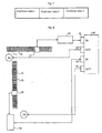
- FIG. 8 An example of a signal processing apparatus of a conventional encoder is shown in Fig. 8 .
- a constitution is shown which is applied to the control of an X-Y table, such as an automatic cutting machine.
- the apparatus shown in the drawing has a scale 10, on which a pattern 11 is engraved with a specific pitch for controlling in the X direction, and an encoder head 12 which moves on this scale 10 and reads this pattern.
- the pattern detection signals read from this encoder head are sent to an encoded signal processor 60 as two sine wave signals with a phase difference, as described in the references mentioned above, and transformed into data signals of positional information.
- These data signals are sent to the input port 81 of a motor controller 80 in the form of serial signals, as mentioned above.
- the motor controller 80 actuates a motor M1 for driving the X axis in a specific device by a distance equal to the difference between the positional data obtained and the position it should move to. Furthermore, this apparatus is constituted in such a way that, even while this movement is taking place, the updated positional data are read and the optimum movement control is performed.
- the control in the Y direction in this drawing is performed in the same way: the apparatus has a scale 30 on which a pattern 31 for control in the Y direction is engraved, an encoder head 32, and an encoded signal processor 70, and this encoded signal processor 70 sends the data signals to the input port 83 of the motor controller 80 and the motor M2 is controlled through the output port 84 in the same manner as described above.
- the motor controller 80 is ordinarily provided with a pair of input (81) and output (82) ports and another pair of input (83) and output (84) ports, for a total of 4 input and output ports.
- This constitution of the input and output ports of the motor controller is the general embodiment for controlling this X-Y table, and is employed in many devices which are currently in widespread use.
- the encoder in this drawing is provided with a sub-scale 20 which measures minute displacements in the Y direction which are orthogonal to the X direction in addition to the main scale 10, which measures the amount of movement in the X direction.
- the constitution of the main scale is the same as above, and the explanation of the elements of this constitution which are given the same numbers as above will be omitted, aside from labeling the encoded signal processor "60a.”
- a grid (engraved lines) perpendicular to the grid (engraved lines) engraved on the main scale 10 is engraved on this sub-scale 20.
- an encoder head 22 is provided, in the same way as for the main scale 10, and the detected signals are sent to the input port 83 of the motor controller as movement data 80 through the encoded signal processor 60b.
- Patent Reference 4 a sensor controller is disclosed in which, after one of a plurality of analog data sensors is selected with a multiplexer, the data are A/D-converted and the A/D-converted digital signals are made into serial signals and sent to the main control part.
- this reference since this reference is concerned with a technology related to the acceptance of sensor data in a digital controller, it is different from the technology which relates to the data transmission of an encoder. Furthermore, this technology only deals with the selection of analog signals from a sensor by a multiplexer; it does not describe or suggest the integration of a plurality of data signals.
- the problems which are to be solved are, first, to provide a signal processing apparatus for encoders which can respond easily and at low cost to encoders which are made to function with high precision and high resolution and in systems which have unusual or extra kinds of inputs and outputs.
- a signal processing apparatus for encoders must be provided which does not require developing a new control apparatus and can solve the problem with only slight modifications of the existing apparatus.
- the signals from a plurality of encoder heads or detectors can be synthesized and transmitted as one signal after being converted to data signals, the signals from a plurality of systems can be received in one port and an existing motor controller can be used without modification.
- the processing of the received signals can be easily dealt with by making slight alterations, such as changing the software in the motor controller.
- the signal processing apparatus for encoders of this invention has the advantage that it provide a signal processing apparatus for encoders which can respond easily and at low cost to encoders which are made to function with high precision and high resolution and in systems which have unusual or extra kinds of inputs and outputs.
- the signal processing apparatus for encoders of this invention converts the detection signals from a plurality of encoders, synthesizes the plurality of data signals obtained, and transmits them as one synthesized data signal.
- the encoders in this invention are not particularly limited as long as they can measure quantities of movement or displacement of the measured objects and output encoded signals; they may be of the rotary type or the linear type. In linear encoders, in particular, the necessity arises of dealing with several different detection directions, as mentioned above. Moreover, the methods of detection of the encoders or the modes of data output are not particularly limited, either; they may be optical, magnetic, or electromagnetic induction types, and the modes of the outputted data may be incremental or absolute.
- the encoder of this invention is provided, at least, with a signal plate, on which a scale for producing symbols (signals), engraved lines, or symbol patterns is placed, and a detector for detecting this pattern which is placed on this signal plate.
- the encoder is a rotary encoder
- the signal plate has a symbol pattern on a rotating circular plate; if it is a linear encoder, the symbol pattern or engraved lines are placed on a scale.
- the detector is of the optical type, it is provided with a light source which emits the light which reads the pattern and an optical detection element which detects the light reflected from the light source on the signal plate or the light passing through the signal plate.
- signal plates or wiring base plates and elements, etc. of well-known types for producing the symbol signals are provided in the same way.
- Desirable constitutions of the linear encoders used in this invention are ones which conform to generally used linear encoders, including optical encoders.
- Optical encoders have, for example, a main scale, on which a grid (engraved lines) in which transparent and opaque parts are arranged with a specific pitch on one side of a reflective glass scale and an index scale, on which a grid (engraved lines) in which transparent and opaque parts are arranged with a specific pitch on one side of a transparent glass placed on the surface of the sensor part; the main scale and index scale are placed opposite each other with a very small gap between them, and the grid of the index scale is arranged in such a way that it is inclined at a slight angle to the grid of the main scale.
- the moire bands are displaced by the interval of the bands and the change of the permeating or reflected light of the slits in the interval is read; in this way, the amount of movement of one pitch can be measured precisely.
- the sensor unit which serves as the detector has a sensor part, which has a glass scale and an opposing index scale, on which a grid (engraved lines) are placed, and an optical sensor, as well as guide rollers, etc., for reducing the vibration of the glass scale slide. Furthermore, besides this constitution, one may also read the grid of the main scale without producing moire bands, and various modes which are known as optical methods may be selected.
- the encoder head has a structure in which it is attached to a movable part, such as a machine tool, which is the object being measured, and contains a sensor unit and has a degree of freedom such that it can follow to a certain extent the variable movements of the object being measured.
- the scale is attached to a fixed part, a machine tool, etc., and the encoder head is attached to the movable part of the machine tool which is the object being measured.
- the amount of movement of this movable part (displacement) is detected as the amount of relative movement of the glass scale and the sensor part of the sensor unit, which moves along this scale.
- the detector of the encoder of this invention converts the pattern on the symbol plate into an electrical signal and outputs an analog signal, at least, in the manner described above.
- This analog signal detects the changes in the pattern of the symbol plate with the detection element, as mentioned above; therefore, the signal level varies corresponding to the pattern of the symbol plate.
- this signal varies in the shape of a sine wave; by using various signal processing techniques, it can be converted into an internal phase signal or a square wave pulse signal.
- This detection signal is preferably two signals with a phase difference; it is especially desirable for it to be detected as two signals with a phase difference of 90 degrees. By using this kind of phase difference signal, the displacement or movement direction of the object being measured can be easily discriminated.
- the circuit for processing this signal can be constituted based on well known circuits which are described in the aforementioned references.
- the detection signal obtained from the signal mentioned above is inputted into the signal processing apparatus of this invention.
- the inputted detection signal is subjected to an analog/digital conversion and a binary digital detection signal is obtained by waveform shaping.
- this digital detection signal is processed by interpolation to increase its resolution, as needed, and converted into a signal for counting, by which the displacement or movement direction can be discriminated, and counted by a counter. Furthermore, the count signal of this counter is outputted as a positional data signal.
- a plurality of output signals from a plurality of encoders are inputted. These encoders may be related to each other or unrelated, but ordinarily the detection signals used as data of the same control system are inputted.
- the "same control system” means, for instance, a combination of data obtained from a main scale used for ordinary measurement and a sub-scale which measures displacements in a direction orthogonal to this.
- a positional data signal is produced from a plurality of detection signals.
- the positional data signals produced are reconstituted into one signal by synthesizing them in the signal processing apparatus.
- the method of synthesizing the plurality of data signals is not particularly limited; two data signals may simply be arranged consecutively. By arranging them consecutively, the signal form can be made simple and the constitution of the device need not be complex. Moreover, they may be synthesized by using well known signal synthesizing means.
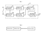
- Fig. 1 is a block diagram which shows the constitution of an example of a signal processing apparatus 50 of this invention.
- the signal processing apparatus 50 has an A/D conversion encoder part 51 which has a first data signal input IN1 and a parallel/serial conversion part 53 which is connected to this A/D conversion encoder part 51.
- the A/D conversion encoder part 51 represents the data signal conversion part which converts the detection signals to digital signals and the parallel/serial conversion part 53 represents the serial signal production part which converts the data signals from the data signal conversion part to serial signals.
- the nth (where n is a natural number 2 or larger) constituent elements are the A/D conversion encoder part 52n which has the nth data signal input INn and the parallel/serial conversion part 54n which is connected to this A/D conversion encoder part 52n.
- the signal process apparatus has the signal synthesis part 55 into which the plurality of output signals from the aforementioned parallel/serial conversion part 53 to the nth parallel/serial conversion part 54n are inputted.
- it has a data sending and receiving part 56 into which the signals synthesized by this signal synthesis part 55 are inputted and which sends and receives signals with an external apparatus.
- the detection signals from the detectors of the various encoders are inputted into the nth (where n is a natural number 2 or greater) A/D conversion encoder part 52n which has the nth data signal input INn. Since the inputted detection signals are two analog phase difference signals in this working example, they are subjected to A/D conversion and converted into digital signals.. The two converted digital phase difference signals are subjected to various well known processes, as needed, in the same way as described above, and converted into data signals which express the positional information or displacement and movement quantities. Furthermore, the aforementioned A/D conversion encoder parts may be placed in the encoder heads.
- the nth system of data signals obtained is ordinary a set of parallel signals, they are sent to the parallel/serial conversion part 53 to the parallel/serial conversion part 54n, respectively, and converted to serial data signals, which are suitable for transmission.
- the converted nth system of serial data signals are sent to the signal synthesis part 55 and synthesized into one synthesized data signal by being arranged consecutively by a desirable mode.
- the A/D conversion encoder parts and the parallel/series conversion parts may be made common ones by a time-sharing operation, etc.
- the method of synthesizing the data is not particularly limited; the first data signal may be held in a first register or memory region, the nth data may be held in the nth register or memory region, and they may be read out successively and held in an (n+1)th or greater register or memory region, or they may be introduced into the transmission process described below as unchanged synthesized data.
- Fig. 2 shows an example of the data signals synthesized in this way.
- the signals shown in this example are arranged serially as the data signals 1, 2, ... n and synthesized as one data signal.
- the synthesis of the data is made simply by making the data into sequentially arranged serial data in this way.
- the synthesis of the data signals is not limited to this method; it may be modified in various ways.
- the synthesized data signals are sent to the data sending and receiving part 56 and transmitted to an external apparatus, not shown in the drawing, by serial transmission.
- the data sending and receiving part 56 performs sending and receiving of signals with the external apparatus as necessary, sending and receiving the needed data and commands. Therefore, it is provided with the control elements, buffer elements, driver elements, etc., necessary for transmission, like well known transmission apparatus.
- the synthesized data signals are sent to the apparatus which receives the data as one data signal, according to the conventional constitution.
- the mode of transmitting the data when they are sent and received is not particularly limited, but one may use a serial transmission means which is ordinarily employed in this kind of apparatus. When serial transmission is used, few transmission lines are needed, and the apparatus can be realized easily using existing elements and circuits. Its operation is also stable and high reliability is obtained. Furthermore, one can also use parallel transmission or wireless transmission, depending on the nature of the apparatus involved.
- serial transmission is desirable, as described above.
- Typical transmission protocols which can be used for the serial transmission are, for example, RS232, RS422, RS485, etc.; the transmission means with the optimum specifications can be selected from these.
- Various kinds of apparatus can be used or selected for sending and receiving the data signals, depending on the purpose of use, mode of use, etc., but a motor controlling apparatus such as a motor controller, is especially recommended in this invention.
- a motor controlling apparatus such as a motor controller
- the advantages of the apparatus of this invention can be fully employed when a motor controller which has a plurality of fixed input/output ports, such as the existing 2-input/2-output type, is used.
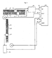
- Fig. 3 is a block drawing which shows one example of the constitution of the system which uses the signal processing apparatus of this invention.
- a sub-scale which measures the quantity of movement in the Y direction, orthogonal to the X direction is used for control on one axis of an X-Y table.
- the X-Y table control system has a scale 10 on which a pattern 11 is engraved at a specific pitch for X direction control and an encoder head 12 which moves over this scale 10 and reads the pattern 11.
- the pattern detection signals which are read from this encoder head are sent to the signal processor 50 as two sine wave signals with a phase difference, as mentioned above.
- the system shown in this drawing is provided with a sub-scale 20 which measures minute displacements in the Y direction, which is orthogonal to the X direction, in addition to the main scale 10, which measures the amount of movement in the X direction.
- a grid (engraved lines) 21 which is parallel to the longitudinal direction of the scale, which is perpendicular to the grid (engraved lines) engraved on the main scale 10, is engraved on this sub-scale 20.
- an encoder head 22 is provided, in the same way as for the main scale 10, and the detected signals are sent to the signal processor 50 in the same manner as for the main scale.
- the aforementioned two systems of detection signals inputted to the signal processor 50 are subjected to processing, including A/D conversion and waveform shaping, and converted to digitized signals. Moreover, as necessary they are processed by interpolation to increase the resolution and converted to count signals which can discriminate the direction of rotation, direction of displacement, and direction of movement, and a specific count processing is performed to produce positional data signals. Since the positional data signals obtained are ordinarily 8-bit, etc., parallel data signals, they are converted to serial data signals suitable for transmission. Moreover, the 2-system serial data signals are synthesized into one signal. The mode of synthesis used may be of various types, as mentioned above, but a desirable mode in this working example is to arrange the serial data consecutively and treat them as one data signal.
- the synthesized data signals are sent to the input port 81 of a motor controller 80, in the same constitution as that of an existing system.
- the motor controller 80 extracts the original data signal by dividing the received data signal into portions of a specific bit length, for example, and uses them in the respective control systems.
- the motor M1 for driving the X axis is actuated through the output port 82 by the difference between the position to be moved and the positional data of the X direction obtained from the main scale, moving the X axis to a specific position.
- the data for the Y direction are corrected by the displacement data for the Y direction obtained from the sub-scale. That is, the minute displacements in the Y direction are detected by the sub-scale placed together with the scale for controlling the X axis, and control can be performed using the more precise positional data in this way.
- the apparatus has a scale 30 on which a pattern 31 for control in the Y direction is engraved, an encoder head 32, and an encoded signal processor 70; this encoded signal processor 70 sends the data signals to the input port 83 of the motor controller 80 and the motor M2 is controlled through the output port 84 in the same manner as described above. That is, the minute displacements in the X direction can be detected by a sub-scale on this Y axis and the data of the X axis can also be corrected.
- the ordinary motor controller 80 is provided with a pair of input (81) and output (82) ports and another pair of input (83) and output (84) ports, for a total of 4 input and output ports. Even a constitution which has three encoders, as described above, can be accommodated with the one motor controller mentioned above.
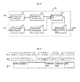
- FIG. 4 is a block diagram showing the constitution of an example of a signal processing apparatus 50 of this invention.
- the signal processing apparatus 50 has an A/D conversion encoder part 51 which has a first data signal input IN1, a parallel/serial conversion part 53 which is connected to this A/D conversion encoder part 51, an A/D conversion encoder part 52 which has a second data signal input IN2, and a parallel/serial conversion part 54 which is connected to this A/D conversion encoder part 52.
- the signal synthesis part 55 to which the two data signals of the aforementioned parallel/serial conversion parts 53 and 54 are inputted and data sending and receiving part 56 into which the signals synthesized by this signal synthesis part 55 are inputted and which sends and receives signals with an external apparatus.
- the A/D conversion encoder part 51 which has the first data signal input IN1 and the A/D conversion encoder part 52 which has the second data signal input IN2 input the detection signals from the detectors of the various encoders, as shown in Fig. 4 .
- the inputted detection signals are two analog phase difference signals in this working example, they are subjected to A/D conversion and converted into digital signals.
- the two converted digital phase difference signals are subjected to various well known processes, as needed, in the same way as described above, and converted into data signals which express the positional information or displacement and movement quantities.
- the two-system data signals obtained are parallel signals, they are sent to the parallel/serial conversion parts 53 and 54, respectively, and converted to serial data signals, which are suitable for transmission.
- the two converted systems of converted serial data signals are sent to the signal synthesis part 55 and synthesized into one synthesized data signal by being arranged successively.
- the synthesized data signals are sent to the data sending and receiving part 56 and transmitted to an external apparatus, not shown in the drawing, through a transmission cable by serial transmission.
- Fig. 5 shows an example of a typical serial signal sent and received in the apparatus of this invention.
- (a) shows the clock
- (b) the signal data and (c) the contents of the data.
- the positional data are sent as single packets.
- the process starts at the falling clock edge.
- the positional data are read and stored, and the position is measured, if necessary.
- a mode command is sent after a delay of 2 clock pulses, and after a further specific clock interval is interposed, a start bit (S), an error bit 1 (F1), and an error bit 2 (F2) are sent.
- the first positional data 1 are sent successively, from the lowest bit LSB (L) to the highest bit MSB (M).
- the second positional data 2 are set, from the lowest bit LSB (L) to the highest bit MSB (M).
- CRC cycle redundancy check
- the "mode command” is a command which prescribes the contents of the data sent; it prescribes the kind of positional data of the encoder, the control commands and data needed to control the encoder and the system, or the presence or absence of the aforementioned CRC.
- the error bits 1 and 2 are added to check for errors in the various checking functions; if necessary one or the other may be omitted.
- the CRC is a so-called “redundancy bit”; it is added to improve the data reliability, and may be omitted in some cases.
- the numbers of bits and clocks needed to transmit the positional data are determined as desired, depending on the nature of the apparatus, etc. Moreover, if necessary, it is possible to transmit additional information following the aforementioned CRC besides the information mentioned above; in this case, a CRC is also added to the additional information.
- the data length (bit length) of the positional data are discriminated; therefore, if the positional data are divided (partitioned) by specific bits, the positional data 1 and 2 can be easily obtained. Furthermore, any of the data mentioned above may be allotted to the positional data 1 and 2 at will.
- the positional data of two encoders can be combined into one set of data by a comparatively simple constitution, in this case, the number of encoders can be increased without making large changes in the existing system, and a system with high performance, high resolution, and high function can be obtained with slight changes.
- FIG. 6 is a block drawing which shows a second example of the constitution of the system which uses the signal processing apparatus of this invention.
- a sub-scale which measures the quantity of movement in the Y direction, orthogonal to the X direction
- a sub-scale 40 for detection in the Z direction, orthogonal to the X and Y directions is also provided.
- an encoder head 42 is provided for the sub-scale 40, in the same way as for the main scale 10, and the detected signals are sent to the signal processor 50 in the same manner as for the main scale. Therefore, three systems of output signals are inputted from the main scale 10, the sub-scale 20, and the sub-scale 40.
- the data signals from the encoder heads 12, 22, and 42, which are the detectors of these three systems, are synthesized in the signal processor 50 and converted into a serial signal in the same way as in Working Example 1, as a single synthesized data signal, as shown in Fig. 7 .
- the order of the synthesized data signals may be determined in any way one wishes.
- the constituent elements which are the same as in Working Example 1 are given the same numbers, and their explanation is omitted.
- the data can be easily accommodated even when the data detected in the control of the X axis are increased to three systems.
- control of an X-Y table was explained by examples in the aforementioned working examples, but this invention is not limited to this kind of constitution; control in a single direction is possible, and various modifications and applications may be made.
- the sub-scales added to the main scale may not only be used for the Y and Z directions, but they may be made into multiple systems, in which the detection of other directional components is added, such as vibration forward and backward in the direction of travel. More precise measurements are possible by detection displacements with many directional components.
- This invention is used to obtain positional information of measuring, machining, and processing equipment, etc. If encoders of types which can read the positional detection patterns linked to the symbol patterns or electromagnetic induction of symbol boards and scales, it can be applied to linear encoders as well as rotary encoders and to incremental as well as absolute types, using optical, magnetic, or induction methods.
Landscapes
- Engineering & Computer Science (AREA)
- General Engineering & Computer Science (AREA)
- Theoretical Computer Science (AREA)
- Human Computer Interaction (AREA)
- Physics & Mathematics (AREA)
- General Physics & Mathematics (AREA)
- Transmission And Conversion Of Sensor Element Output (AREA)
- Arrangements For Transmission Of Measured Signals (AREA)
- Optical Transform (AREA)
Claims (3)
- Système de mesure comprenant un appareil de traitement de signaux (50) et des codeurs pour mesurer des quantités de mouvement ou de déplacement, lequel est conçu pour convertir les signaux de détection (IN1, ..., INn) depuis plusieurs codeurs en signaux de données série, synthétiser lesdits plusieurs signaux de données obtenus, et les transmettre vers un appareil externe sous forme d'un signal de données synthétisé, caractérisé en ce que lesdits plusieurs codeurs possèdent des échelles principales (10, 30) conçues pour mesurer les quantités de mouvement dans les directions de mesure principales, et des sous-échelles (20, 40) conçues pour détecter des déplacements minuscules dans les directions orthogonales aux directions de mesure principales.
- Système de mesure selon la revendication 1, dans lequel les signaux de données synthétisés susmentionnés comprennent plusieurs signaux de données qui sont joints les uns aux autres et agencés de manière consécutive.
- Système de mesure selon l'une quelconque des revendications 1 ou 2, lequel comprend plusieurs parties de conversion de signaux de données (51, ..., 52n) conçues pour convertir les signaux de détection en signaux de données, plusieurs parties de production de signaux série (53, ..., 54n) conçues pour convertir les signaux de données provenant des parties de conversion de signaux de données en signaux série, une partie de synthèse de signaux (55) conçue pour synthétiser les signaux de données provenant des parties de production de signaux série, et une partie de transmission de signaux (56) conçue pour transmettre les signaux de données série synthétisés dans la partie de synthèse de signaux vers un appareil externe.
Applications Claiming Priority (1)
| Application Number | Priority Date | Filing Date | Title |
|---|---|---|---|
| JP2011001938A JP5660671B2 (ja) | 2011-01-07 | 2011-01-07 | エンコーダの信号処理装置 |
Publications (2)
| Publication Number | Publication Date |
|---|---|
| EP2474902A1 EP2474902A1 (fr) | 2012-07-11 |
| EP2474902B1 true EP2474902B1 (fr) | 2015-01-07 |
Family
ID=45400897
Family Applications (1)
| Application Number | Title | Priority Date | Filing Date |
|---|---|---|---|
| EP11188757.6A Active EP2474902B1 (fr) | 2011-01-07 | 2011-11-11 | Appareil de traitement de signal pour codeurs |
Country Status (2)
| Country | Link |
|---|---|
| EP (1) | EP2474902B1 (fr) |
| JP (1) | JP5660671B2 (fr) |
Families Citing this family (6)
| Publication number | Priority date | Publication date | Assignee | Title |
|---|---|---|---|---|
| JP6479309B2 (ja) * | 2012-08-20 | 2019-03-06 | Dmg森精機株式会社 | スケール装置、位置情報生成方法及び多軸ステージ装置 |
| JP6285633B2 (ja) * | 2013-02-07 | 2018-02-28 | 株式会社ミツトヨ | セパレート式エンコーダ |
| JP2016178601A (ja) * | 2015-03-23 | 2016-10-06 | セイコーエプソン株式会社 | データ処理回路、物理量検出用回路、物理量検出装置、電子機器及び移動体 |
| JP6686352B2 (ja) * | 2015-09-30 | 2020-04-22 | サンケン電気株式会社 | 温度検出回路 |
| TWI815834B (zh) * | 2017-12-22 | 2023-09-21 | 瑞士商施內貝格爾控股公司 | 用來確定絕對位置的線性路線測量儀和用這種路線測量儀進行線性導引 |
| JP7028652B2 (ja) * | 2018-01-16 | 2022-03-02 | 株式会社ミツトヨ | 測定装置 |
Family Cites Families (9)
| Publication number | Priority date | Publication date | Assignee | Title |
|---|---|---|---|---|
| DE3635511A1 (de) * | 1986-10-18 | 1988-04-28 | Zeiss Carl Fa | Halterung fuer mass- und formverkoerperung |
| JPH04342010A (ja) | 1991-05-20 | 1992-11-27 | Nec Corp | センサ制御器 |
| JP2611124B2 (ja) * | 1993-07-13 | 1997-05-21 | 川崎重工業株式会社 | エンコーダシステム |
| JPH0736017U (ja) * | 1993-12-08 | 1995-07-04 | 株式会社ニコン | エンコーダ |
| JP3628908B2 (ja) * | 1999-04-30 | 2005-03-16 | 沖電気工業株式会社 | 符号化信号処理装置および符号化信号の同期処理方法 |
| JP4156223B2 (ja) | 2001-10-19 | 2008-09-24 | サムタク株式会社 | リニアスケール |
| JP3986074B2 (ja) | 2004-03-04 | 2007-10-03 | サムタク株式会社 | 多回転型絶対値エンコーダ |
| TWI471531B (zh) * | 2008-08-26 | 2015-02-01 | 尼康股份有限公司 | Encoder system, signal processing method |
| JP5194247B2 (ja) * | 2009-01-07 | 2013-05-08 | 多摩川精機株式会社 | 回転角度検出システム |
-
2011
- 2011-01-07 JP JP2011001938A patent/JP5660671B2/ja active Active
- 2011-11-11 EP EP11188757.6A patent/EP2474902B1/fr active Active
Also Published As
| Publication number | Publication date |
|---|---|
| JP5660671B2 (ja) | 2015-01-28 |
| EP2474902A1 (fr) | 2012-07-11 |
| JP2012145359A (ja) | 2012-08-02 |
Similar Documents
| Publication | Publication Date | Title |
|---|---|---|
| EP2474902A1 (fr) | Appareil de traitement de signal pour codeurs | |
| CA1203625A (fr) | Detecteur de position d'un organe mobile, et ses montage et fonctionnement | |
| CN110702055B (zh) | 用于角度测量的装置和方法 | |
| US7571552B2 (en) | Scale reading apparatus | |
| JP3143310B2 (ja) | 位置検出装置、補正機能付位置検出装置、位置検出方法、および、位置検出装置の補正方法 | |
| EP0666520B1 (fr) | Procédé et dispositif de détection de la position | |
| US4730110A (en) | Shaft position encoder | |
| CN102275093B (zh) | 基于五轴数控系统的工件测量系统 | |
| EP0139769B1 (fr) | Systeme de detection de la position absolue d'un systeme de servo-commande | |
| CN101419066B (zh) | 一种两轴随动控制检测齿轮齿廓和螺旋线的方法 | |
| JPH0471444B2 (fr) | ||
| CN101332524A (zh) | 数控展成磨齿机及展成磨齿机的数控装置和驱动方法 | |
| US7925462B2 (en) | Position-measuring device and method for transmitting information concerning movement | |
| JPS59188518A (ja) | サ−ボ制御系の絶対位置検出方式 | |
| US5642297A (en) | Apparatus and method for measuring the kinematic accuracy in machines and mechanisms using absolute encoders | |
| US11874107B2 (en) | Device and method for processing rotation-dependent measured values | |
| EP0201106A2 (fr) | Codeur absolu de position | |
| US6356219B1 (en) | Calibrated encoder multiplier | |
| EP0267966B1 (fr) | Systeme de positionnement | |
| CN108955617B (zh) | 偏斜检测器 | |
| US6070132A (en) | Position detecting apparatus | |
| JP5455428B2 (ja) | 測定装置 | |
| JP2009271076A6 (ja) | 位置および/または速度を検出する測定装置 | |
| EP0185776B1 (fr) | Dispositif de detection de la position absolue d'un systeme de servocommande | |
| CN102707667B (zh) | 凸轮轮廓检测方法 |
Legal Events
| Date | Code | Title | Description |
|---|---|---|---|
| PUAI | Public reference made under article 153(3) epc to a published international application that has entered the european phase |
Free format text: ORIGINAL CODE: 0009012 |
|
| AK | Designated contracting states |
Kind code of ref document: A1 Designated state(s): AL AT BE BG CH CY CZ DE DK EE ES FI FR GB GR HR HU IE IS IT LI LT LU LV MC MK MT NL NO PL PT RO RS SE SI SK SM TR |
|
| AX | Request for extension of the european patent |
Extension state: BA ME |
|
| 17P | Request for examination filed |
Effective date: 20130111 |
|
| GRAP | Despatch of communication of intention to grant a patent |
Free format text: ORIGINAL CODE: EPIDOSNIGR1 |
|
| INTG | Intention to grant announced |
Effective date: 20141028 |
|
| GRAS | Grant fee paid |
Free format text: ORIGINAL CODE: EPIDOSNIGR3 |
|
| GRAA | (expected) grant |
Free format text: ORIGINAL CODE: 0009210 |
|
| AK | Designated contracting states |
Kind code of ref document: B1 Designated state(s): AL AT BE BG CH CY CZ DE DK EE ES FI FR GB GR HR HU IE IS IT LI LT LU LV MC MK MT NL NO PL PT RO RS SE SI SK SM TR |
|
| REG | Reference to a national code |
Ref country code: GB Ref legal event code: FG4D |
|
| REG | Reference to a national code |
Ref country code: CH Ref legal event code: EP |
|
| REG | Reference to a national code |
Ref country code: IE Ref legal event code: FG4D |
|
| REG | Reference to a national code |
Ref country code: AT Ref legal event code: REF Ref document number: 706148 Country of ref document: AT Kind code of ref document: T Effective date: 20150215 |
|
| REG | Reference to a national code |
Ref country code: DE Ref legal event code: R096 Ref document number: 602011012842 Country of ref document: DE Effective date: 20150226 |
|
| REG | Reference to a national code |
Ref country code: NL Ref legal event code: VDEP Effective date: 20150107 |
|
| REG | Reference to a national code |
Ref country code: AT Ref legal event code: MK05 Ref document number: 706148 Country of ref document: AT Kind code of ref document: T Effective date: 20150107 |
|
| REG | Reference to a national code |
Ref country code: LT Ref legal event code: MG4D |
|
| PG25 | Lapsed in a contracting state [announced via postgrant information from national office to epo] |
Ref country code: HR Free format text: LAPSE BECAUSE OF FAILURE TO SUBMIT A TRANSLATION OF THE DESCRIPTION OR TO PAY THE FEE WITHIN THE PRESCRIBED TIME-LIMIT Effective date: 20150107 Ref country code: NO Free format text: LAPSE BECAUSE OF FAILURE TO SUBMIT A TRANSLATION OF THE DESCRIPTION OR TO PAY THE FEE WITHIN THE PRESCRIBED TIME-LIMIT Effective date: 20150407 Ref country code: ES Free format text: LAPSE BECAUSE OF FAILURE TO SUBMIT A TRANSLATION OF THE DESCRIPTION OR TO PAY THE FEE WITHIN THE PRESCRIBED TIME-LIMIT Effective date: 20150107 Ref country code: FI Free format text: LAPSE BECAUSE OF FAILURE TO SUBMIT A TRANSLATION OF THE DESCRIPTION OR TO PAY THE FEE WITHIN THE PRESCRIBED TIME-LIMIT Effective date: 20150107 Ref country code: LT Free format text: LAPSE BECAUSE OF FAILURE TO SUBMIT A TRANSLATION OF THE DESCRIPTION OR TO PAY THE FEE WITHIN THE PRESCRIBED TIME-LIMIT Effective date: 20150107 Ref country code: SE Free format text: LAPSE BECAUSE OF FAILURE TO SUBMIT A TRANSLATION OF THE DESCRIPTION OR TO PAY THE FEE WITHIN THE PRESCRIBED TIME-LIMIT Effective date: 20150107 Ref country code: BG Free format text: LAPSE BECAUSE OF FAILURE TO SUBMIT A TRANSLATION OF THE DESCRIPTION OR TO PAY THE FEE WITHIN THE PRESCRIBED TIME-LIMIT Effective date: 20150407 |
|
| PG25 | Lapsed in a contracting state [announced via postgrant information from national office to epo] |
Ref country code: PL Free format text: LAPSE BECAUSE OF FAILURE TO SUBMIT A TRANSLATION OF THE DESCRIPTION OR TO PAY THE FEE WITHIN THE PRESCRIBED TIME-LIMIT Effective date: 20150107 Ref country code: IS Free format text: LAPSE BECAUSE OF FAILURE TO SUBMIT A TRANSLATION OF THE DESCRIPTION OR TO PAY THE FEE WITHIN THE PRESCRIBED TIME-LIMIT Effective date: 20150507 Ref country code: RS Free format text: LAPSE BECAUSE OF FAILURE TO SUBMIT A TRANSLATION OF THE DESCRIPTION OR TO PAY THE FEE WITHIN THE PRESCRIBED TIME-LIMIT Effective date: 20150107 Ref country code: AT Free format text: LAPSE BECAUSE OF FAILURE TO SUBMIT A TRANSLATION OF THE DESCRIPTION OR TO PAY THE FEE WITHIN THE PRESCRIBED TIME-LIMIT Effective date: 20150107 Ref country code: NL Free format text: LAPSE BECAUSE OF FAILURE TO SUBMIT A TRANSLATION OF THE DESCRIPTION OR TO PAY THE FEE WITHIN THE PRESCRIBED TIME-LIMIT Effective date: 20150107 Ref country code: LV Free format text: LAPSE BECAUSE OF FAILURE TO SUBMIT A TRANSLATION OF THE DESCRIPTION OR TO PAY THE FEE WITHIN THE PRESCRIBED TIME-LIMIT Effective date: 20150107 Ref country code: GR Free format text: LAPSE BECAUSE OF FAILURE TO SUBMIT A TRANSLATION OF THE DESCRIPTION OR TO PAY THE FEE WITHIN THE PRESCRIBED TIME-LIMIT Effective date: 20150408 |
|
| REG | Reference to a national code |
Ref country code: DE Ref legal event code: R097 Ref document number: 602011012842 Country of ref document: DE |
|
| PG25 | Lapsed in a contracting state [announced via postgrant information from national office to epo] |
Ref country code: DK Free format text: LAPSE BECAUSE OF FAILURE TO SUBMIT A TRANSLATION OF THE DESCRIPTION OR TO PAY THE FEE WITHIN THE PRESCRIBED TIME-LIMIT Effective date: 20150107 Ref country code: CZ Free format text: LAPSE BECAUSE OF FAILURE TO SUBMIT A TRANSLATION OF THE DESCRIPTION OR TO PAY THE FEE WITHIN THE PRESCRIBED TIME-LIMIT Effective date: 20150107 Ref country code: SK Free format text: LAPSE BECAUSE OF FAILURE TO SUBMIT A TRANSLATION OF THE DESCRIPTION OR TO PAY THE FEE WITHIN THE PRESCRIBED TIME-LIMIT Effective date: 20150107 Ref country code: RO Free format text: LAPSE BECAUSE OF FAILURE TO SUBMIT A TRANSLATION OF THE DESCRIPTION OR TO PAY THE FEE WITHIN THE PRESCRIBED TIME-LIMIT Effective date: 20150107 Ref country code: EE Free format text: LAPSE BECAUSE OF FAILURE TO SUBMIT A TRANSLATION OF THE DESCRIPTION OR TO PAY THE FEE WITHIN THE PRESCRIBED TIME-LIMIT Effective date: 20150107 |
|
| PLBE | No opposition filed within time limit |
Free format text: ORIGINAL CODE: 0009261 |
|
| STAA | Information on the status of an ep patent application or granted ep patent |
Free format text: STATUS: NO OPPOSITION FILED WITHIN TIME LIMIT |
|
| 26N | No opposition filed |
Effective date: 20151008 |
|
| PG25 | Lapsed in a contracting state [announced via postgrant information from national office to epo] |
Ref country code: IT Free format text: LAPSE BECAUSE OF FAILURE TO SUBMIT A TRANSLATION OF THE DESCRIPTION OR TO PAY THE FEE WITHIN THE PRESCRIBED TIME-LIMIT Effective date: 20150107 |
|
| PG25 | Lapsed in a contracting state [announced via postgrant information from national office to epo] |
Ref country code: SI Free format text: LAPSE BECAUSE OF FAILURE TO SUBMIT A TRANSLATION OF THE DESCRIPTION OR TO PAY THE FEE WITHIN THE PRESCRIBED TIME-LIMIT Effective date: 20150107 |
|
| PG25 | Lapsed in a contracting state [announced via postgrant information from national office to epo] |
Ref country code: BE Free format text: LAPSE BECAUSE OF FAILURE TO SUBMIT A TRANSLATION OF THE DESCRIPTION OR TO PAY THE FEE WITHIN THE PRESCRIBED TIME-LIMIT Effective date: 20150107 |
|
| PG25 | Lapsed in a contracting state [announced via postgrant information from national office to epo] |
Ref country code: MC Free format text: LAPSE BECAUSE OF FAILURE TO SUBMIT A TRANSLATION OF THE DESCRIPTION OR TO PAY THE FEE WITHIN THE PRESCRIBED TIME-LIMIT Effective date: 20150107 Ref country code: LU Free format text: LAPSE BECAUSE OF FAILURE TO SUBMIT A TRANSLATION OF THE DESCRIPTION OR TO PAY THE FEE WITHIN THE PRESCRIBED TIME-LIMIT Effective date: 20151111 |
|
| REG | Reference to a national code |
Ref country code: CH Ref legal event code: PL |
|
| PG25 | Lapsed in a contracting state [announced via postgrant information from national office to epo] |
Ref country code: CH Free format text: LAPSE BECAUSE OF NON-PAYMENT OF DUE FEES Effective date: 20151130 Ref country code: LI Free format text: LAPSE BECAUSE OF NON-PAYMENT OF DUE FEES Effective date: 20151130 |
|
| REG | Reference to a national code |
Ref country code: IE Ref legal event code: MM4A |
|
| REG | Reference to a national code |
Ref country code: FR Ref legal event code: ST Effective date: 20160729 |
|
| PG25 | Lapsed in a contracting state [announced via postgrant information from national office to epo] |
Ref country code: IE Free format text: LAPSE BECAUSE OF NON-PAYMENT OF DUE FEES Effective date: 20151111 |
|
| PG25 | Lapsed in a contracting state [announced via postgrant information from national office to epo] |
Ref country code: FR Free format text: LAPSE BECAUSE OF NON-PAYMENT OF DUE FEES Effective date: 20151130 |
|
| PG25 | Lapsed in a contracting state [announced via postgrant information from national office to epo] |
Ref country code: SM Free format text: LAPSE BECAUSE OF FAILURE TO SUBMIT A TRANSLATION OF THE DESCRIPTION OR TO PAY THE FEE WITHIN THE PRESCRIBED TIME-LIMIT Effective date: 20150107 Ref country code: HU Free format text: LAPSE BECAUSE OF FAILURE TO SUBMIT A TRANSLATION OF THE DESCRIPTION OR TO PAY THE FEE WITHIN THE PRESCRIBED TIME-LIMIT; INVALID AB INITIO Effective date: 20111111 |
|
| PG25 | Lapsed in a contracting state [announced via postgrant information from national office to epo] |
Ref country code: CY Free format text: LAPSE BECAUSE OF FAILURE TO SUBMIT A TRANSLATION OF THE DESCRIPTION OR TO PAY THE FEE WITHIN THE PRESCRIBED TIME-LIMIT Effective date: 20150107 |
|
| PG25 | Lapsed in a contracting state [announced via postgrant information from national office to epo] |
Ref country code: TR Free format text: LAPSE BECAUSE OF FAILURE TO SUBMIT A TRANSLATION OF THE DESCRIPTION OR TO PAY THE FEE WITHIN THE PRESCRIBED TIME-LIMIT Effective date: 20150107 Ref country code: MT Free format text: LAPSE BECAUSE OF FAILURE TO SUBMIT A TRANSLATION OF THE DESCRIPTION OR TO PAY THE FEE WITHIN THE PRESCRIBED TIME-LIMIT Effective date: 20150107 |
|
| PG25 | Lapsed in a contracting state [announced via postgrant information from national office to epo] |
Ref country code: PT Free format text: LAPSE BECAUSE OF FAILURE TO SUBMIT A TRANSLATION OF THE DESCRIPTION OR TO PAY THE FEE WITHIN THE PRESCRIBED TIME-LIMIT Effective date: 20150107 Ref country code: MK Free format text: LAPSE BECAUSE OF FAILURE TO SUBMIT A TRANSLATION OF THE DESCRIPTION OR TO PAY THE FEE WITHIN THE PRESCRIBED TIME-LIMIT Effective date: 20150107 |
|
| PG25 | Lapsed in a contracting state [announced via postgrant information from national office to epo] |
Ref country code: AL Free format text: LAPSE BECAUSE OF FAILURE TO SUBMIT A TRANSLATION OF THE DESCRIPTION OR TO PAY THE FEE WITHIN THE PRESCRIBED TIME-LIMIT Effective date: 20150107 |
|
| PGFP | Annual fee paid to national office [announced via postgrant information from national office to epo] |
Ref country code: DE Payment date: 20251119 Year of fee payment: 15 |
|
| PGFP | Annual fee paid to national office [announced via postgrant information from national office to epo] |
Ref country code: GB Payment date: 20251121 Year of fee payment: 15 |